Juniper Networks
NetScreen &
SSG Firewalls
Configuring
Rob Cameron
Technical EditorBrad Woodberg
Mohan Krishnamurthy Madwachar
Mike Swarm
Neil R. Wyler
Matthew Albers
FOREWORD
BY SCOTT KRIENS
®
(collectively “Makers”) of this book (“the Work”) do not guarantee or warrant the results to be obtained from the Work.
There is no guarantee of any kind, expressed or implied, regarding the Work or its contents.The Work is sold AS IS and WITHOUT WARRANTY.You may have other legal rights, which vary from state to state.
In no event will Makers be liable to you for damages, including any loss of profits, lost savings, or other inci-dental or consequential damages arising out from the Work or its contents. Because some states do not allow the exclusion or limitation of liability for consequential or incidental damages, the above limitation may not apply to you.
You should always use reasonable care, including backup and other appropriate precautions, when working with computers, networks, data, and files.
Syngress Media®, Syngress®, “Career Advancement Through Skill Enhancement®,” “Ask the Author UPDATE®,” and “Hack Proofing®,” are registered trademarks of Syngress Publishing, Inc. “Syngress:The Definition of a Serious Security Library”™, “Mission Critical™,” and “The Only Way to Stop a Hacker is to Think Like One™”are trademarks of Syngress Publishing, Inc. Brands and product names mentioned in this book are trademarks or service marks of their respective companies.
KEY SERIAL NUMBER
001 HJIRTCV764 002 PO9873D5FG 003 829KM8NJH2 004 5489IJJLPP 005 CVPLQ6WQ23 006 VBP965T5T5 007 HJJJ863WD3E 008 2987GVTWMK 009 629MP5SDJT 010 IMWQ295T6T
PUBLISHED BY Syngress Publishing, Inc. 800 Hingham Street Rockland, MA 02370
Configuring Networks NetScreen & SSG Firewalls
Copyright © 2007 by Syngress Publishing, Inc. All rights reserved. Except as permitted under the Copyright Act of 1976, no part of this publication may be reproduced or distributed in any form or by any means, or stored in a database or retrieval system, without the prior written permission of the publisher, with the exception that the program listings may be entered, stored, and executed in a computer system, but they may not be reproduced for publication.
1 2 3 4 5 6 7 8 9 0 ISBN-10: 1-59749-118-7 ISBN-13: 978-1-59749-118-1
Publisher: Andrew Williams Page Layout and Art: Patricia Lupien Acquisitions Editor: Gary Byrne Copy Editors: Mike McGee, Sandy Jolley Technical Editor: Rob Cameron Indexer: Nara Wood
Cover Designer: Michael Kavish
Distributed by O’Reilly Media, Inc. in the United States and Canada.
iii
Lead Author
and Technical Editor
Rob Cameron
( JNCIS-FWV, JNCIA-M, CCSP, CCSE+) is a
Security Solutions Engineer for Juniper Networks. He currently
works to design security solutions for Juniper Networks that are
considered best practice designs. Rob specializes in network security
architecture, firewall deployment, risk management, and
high-avail-ability designs. His background includes five years of security
con-sulting for more than 300 customers.This is Rob’s second book; the
previous one being Configuring NetScreen Firewalls
(ISBN:
1-932266-39-9) published by Syngress Publishing in 2004.
Matthew Albers
(CCNP, CCDA, JNCIA-M, JNCIS-FWV,
JNCIA-IDP) is a senior systems engineer for Juniper Networks. He
currently serves his enterprise customers in the Northern Ohio
marketplace. His specialties include routing platforms, WAN
acceler-ation, firewall/VPNs, intrusion prevention, strategic network
plan-ning, network architecture and design, and network troubleshooting
and optimization. Matthew’s background includes positions as a
senior engineer at First Virtual Communications, Lucent
Technologies, and Bay Networks.
Matthew wrote Chapter 1 and cowrote Chapter 11.
Ralph Bonnell
(CISSP, LPIC-2, CCSI, CCNA, MCSE: Security) is
a senior information security consultant at Accuvant in Denver, CO.
His primary responsibilities include the deployment of various
net-work security products and product training. His specialties include
NetScreen deployments, Linux client and server deployments,
Check Point training, firewall clustering, and PHP Web
program-ming. Ralph also runs a Linux consulting firm called Linux
Friendly. Before moving to Colorado, Ralph was a senior security
engineer and instructor at Mission Critical Systems, a Gold Check
Point partner and training center in South Florida.
Ralph cowrote Chapter 11.
Mohan Krishnamurthy Madwachar
( JNCIA-FWV, CWNA, and
CCSA) is AVP-Infrastructure Services for ADG Infotek, Inc.,
Almoayed Group, Bahrain. Almoayed Group is a leading systems
integration group that has branches in seven countries and executes
projects in nearly 15 countries. Mohan is a key contributor to the
company’s infrastructure services division and plays a key role in the
organization’s network security and training initiatives. Mohan has a
strong networking, security, and training background. His tenure
with companies such as Schlumberger Omnes and Secure Network
Solutions India adds to his experience and expertise in
imple-menting large and complex network and security projects.
Mohan holds leading IT industry certifications and is a member
of the IEEE and PMI.
Mohan would like to dedicate his contributions to this book to
his sister, Geetha Prakash, and her husband, C.V. Prakash, and their
son, Pragith Prakash.
Mohan has coauthored the book Designing and Building
Enterprise DMZs
(ISBN: 1-597491004), published by Syngress
Publishing. He also writes in newspaper columns on various subjects
and has contributed to leading content companies as a technical
writer and a subject matter expert.
v
Mike Swarm
is a Security Solutions Engineer at Juniper
Networks. Mike consults with Juniper’s technical field and customer
communities worldwide on security design practices. Mike has over
a decade of experience focused on network security. Prior to
Juniper Networks and its NetScreen Technologies acquisition, Mike
has been a Systems Engineer at FTP Software and Firefox
Communications.
Mike wrote Chapter 10.
Brad Woodberg
( JNCIS-FWV, JNCIS-M, IDP,
JNCIA-SSL, CCNP) is a Security Consultant at Networks Group Inc. in
Brighton, MI. At Networks Group his primary focus is designing
and implementing security solutions for clients ranging from small
business to Fortune 500 companies. His main areas of expertise
include network perimeter security, intrusion prevention, security
analysis, and network infrastructure. Outside of work he has a great
interest in proof-of-concept vulnerability analysis, open source
inte-gration/development, and computer architecture.
Brad currently holds a bachelor’s degree in Computer
Engineering from Michigan State University, and he participates
with local security organizations. He also mentors and gives lectures
to students interested in the computer network field.
Brad wrote Chapters 5–8 and contributed to Chapter 13. He also
assisted in the technical editing of several chapters.
tele-vision interviews regarding different areas of information security.
He was the Lead Author and Technical Editor of Aggressive Network
Self-Defense
(Syngress, 1-931836-20-5) and serves on the advisory
board for a local technical college.
vii
Contents
Foreword . . . xiii
Chapter 1 Networking, Security, and the Firewall . . . 1
Introduction . . . .2
Understanding Networking . . . .3
The OSI Model . . . .3
Moving Data along with TCP/IP . . . .6
Understanding Security Basics . . . .17
Understanding Firewall Basics . . . .26
Types of Firewalls . . . .26
Firewall Ideologies . . . .31
DMZ Concepts . . . .31
Traffic Flow Concepts . . . .35
Networks with and without DMZs . . . .38
DMZ Design Fundamentals . . . .41
Designing End-to-End Security for Data Transmission between Hosts on the Network . . . .42
Traffic Flow and Protocol Fundamentals . . . .43
Summary . . . .44
Solutions Fast Track . . . .45
Frequently Asked Questions . . . .46
Chapter 2 Dissecting the Juniper Firewall . . . 49
Introduction . . . .50
The Juniper Security Product Offerings . . . .51
Juniper Firewalls . . . .52
SSL VPN . . . .53
Intrusion Detection and Prevention . . . .54
Unified Access Control (UAC) . . . .56
The Juniper Firewall Core Technologies . . . .57
Zones . . . .57
Virtual Routers . . . .57
Interface Modes . . . .58
Policies . . . .58
VPN . . . .59
Intrusion Prevention . . . .59
Device Architecture . . . .61
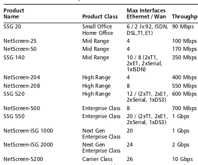
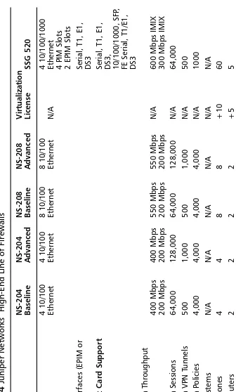
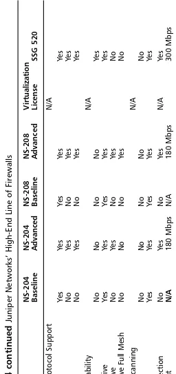
The NetScreen and SSG Firewall Product Line . . . .63
Product Line . . . .63
Summary . . . .85
Solutions Fast Track . . . .86
Frequently Asked Questions . . . .87
Chapter 3 Deploying Juniper Firewalls. . . 89
Introduction . . . .90
Managing Your Juniper Firewall . . . .90
Juniper Management Options . . . .91
Administrative Users . . . .93
The Local File System and the Configuration File . . . .95
Using the Command Line Interface . . . .99
Using the Web User Interface . . . .103
Securing the Management Interface . . . .104
Updating ScreenOS . . . .118
System Recovery . . . .119
Configuring Your Firewall for the First Time . . . .121
Virtual Routers . . . .123
Types of Interfaces . . . .123
Configuring Security Zones . . . .126
Configuring Your Firewall for the Network . . . .131
Binding an Interface to a Zone . . . .132
Setting Up IP Addressing . . . .133
Configuring the DHCP Client . . . .133
Using PPPoE . . . .133
Interface Speed Modes . . . .135
Port Mode Configuration . . . .136
Bridge Groups . . . .137
Configuring Basic Network Routing . . . .140
Configuring System Services . . . .142
Setting the Time . . . .143
DHCP Server . . . .145
DNS . . . .147
SNMP . . . .149
Syslog . . . .151
Web Trends . . . .152
Resources . . . .153
Summary . . . .154
Solutions Fast Track . . . .154
Frequently Asked Questions . . . .156
Chapter 4 Policy Configuration . . . 157
Introduction . . . .158
Firewall Policies . . . .158
Theory of Access Control . . . .160
Types of Juniper Policies . . . .162
Policy Checking . . . .164
Getting Ready to Make a Policy . . . .166
Policy Components . . . .167
Zones . . . .167
Address Book Entries . . . .168
Services . . . .172
Creating Policies . . . .176
Creating a Policy . . . .177
Summary . . . .187
Solutions Fast Track . . . .187
Frequently Asked Questions . . . .188
Chapter 5 Advanced Policy Configuration . . . 191
Introduction . . . .192
Traffic-Shaping Fundamentals . . . .192
The Need for Traffic Shaping . . . .192
How Traffic Shaping Works . . . .195
Choosing the Traffic-Shaping Type . . . .196
Deploying Traffic Shaping on Juniper Firewalls . . . .197
Methods to Enforce Traffic Shaping . . . .197
Traffic-Shaping Mechanics . . . .202
Traffic-Shaping Examples . . . .205
Advanced Policy Options . . . .215
Counting . . . .216
Scheduling . . . .222
Summary . . . .228
Solutions Fast Track . . . .228
Frequently Asked Questions . . . .230
Authentication Users . . . .239
Internal Authentication Server . . . .252
Configuring the Local Authentication Server . . . .253
External Authentication Servers . . . .254
Policy-Based User Authentication . . . .269
Explanation of Policy-Based Authentication . . . .269
Configuring Policies with User Auth . . . .270
802.1x Authentication . . . .277
Components of 802.1x . . . .278
Enhancing Authentication . . . .284
Firewall Banner Messages . . . .284
Group Expressions . . . .287
Summary . . . .289
Solutions Fast Track . . . .289
Frequently Asked Questions . . . .291
Chapter 7 Routing . . . 293
Introduction . . . .294
Virtual Routers . . . .294
Virtual Routers on Juniper Firewalls . . . .295
Routing Selection Process . . . .298
Equal Cost Multiple Path . . . .299
Virtual Router Properties . . . .300
Route Maps and Access Lists . . . .306
Route Redistribution . . . .311
Importing and Exporting Routes . . . .311
Static Routing . . . .313
Using Static Routes on Juniper Firewalls . . . .314
Routing Information Protocol . . . .321
RIP Overview . . . .322
RIP Informational Commands . . . .332
Open Shortest Path First . . . .335
Concepts and Terminology . . . .336
Configuring OSPF . . . .341
OSPF Informational Commands . . . .350
Border Gateway Protocol . . . .354
Overview of BGP . . . .354
Configuring BGP . . . .358
BGP Informational Commands . . . .372
Route Redistribution . . . .375
Redistributing Routes in the Juniper Firewall . . . .375
Redistributing Routes between Routing Protocols . . . .376
Redistributing Routes into BGP . . . .380
Policy-Based Routing . . . .383
Components of PBR . . . .383
Summary . . . .393
Solutions Fast Track . . . .393
Frequently Asked Questions . . . .396
Chapter 8 Address Translation . . . 399
Introduction . . . .400
Overview of Address Translation . . . .400
Port Address Translation . . . .401
Advantages of Address Translation . . . .402
Disadvantages of Address Translation . . . .403
Juniper NAT Overview . . . .404
Juniper Packet Flow . . . .405
Source NAT . . . .406
Policy-Based Source NAT . . . .417
Destination NAT . . . .428
Policy-Based Destination NAT . . . .433
Summary . . . .446
Links to Sites . . . .446
Solutions Fast Track . . . .446
Frequently Asked Questions . . . .449
Chapter 9 Transparent Mode . . . 457
Introduction . . . .458
Interface Modes . . . .458
Understanding How Transport Mode Works . . . .459
Configuring a Device to Use Transport Mode . . . .462
Transparent Mode Deployment Options . . . .466
Summary . . . .476
Solutions Fast Track . . . .477
Frequently Asked Questions . . . .478
Chapter 10 Attack Detection and Defense. . . 479
Introduction . . . .480
Understanding Attacks . . . .480
Old Root Causes, New Attacks . . . .482
Unified Threat Management . . . .482
Vulnerability Databases . . . .482
Bug Databases . . . .483
Common Name Dictionary . . . .483
The Juniper Security Research Team . . . .483
Understanding the Anatomy of an Attack . . . .484
The Three Phases of a Hack . . . .484
Script Kiddies . . . .484
Black Hat Hackers . . . .485
Worms, Viruses, and Other Automated Malware . . . .487
Configuring Screen Settings . . . .490
UDP Data Rate Limiting . . . .497
TCP/IP Protocol Anomaly Detection . . . .498
Applying Deep Inspection . . . .501
Deep Inspection Concepts . . . .503
Deep Inspection Planning . . . .505
Getting the Database . . . .507
Using Attack Objects . . . .510
Setting Up Content Filtering . . . .524
Web Filtering . . . .524
Antivirus . . . .532
Antivirus Rules . . . .538
Understanding Application Layer Gateways . . . .540
Applying Best Practices . . . .542
Defense-in-Depth . . . .542
Zone Isolation . . . .542
Egress Filtering . . . .543
Explicit Permits, Implicit Denies . . . .543
Retain Monitoring Data . . . .543
Keeping Systems Updated . . . .543
Summary . . . .544
Solutions Fast Track . . . .545
Frequently Asked Questions . . . .548
Chapter 11 VPN Theory and Usage . . . 551
Introduction . . . .552
IPSec Modes . . . .553
Protocols . . . .553
Key Management . . . .555
Security Associations . . . .556
IPSec Tunnel Negotiations . . . .556
Phase 1 . . . .557
Phase 2 . . . .558
Public Key Cryptography . . . .559
PKI . . . .560
Certificates . . . .560
CRLs . . . .561
How to Use VPNs in NetScreen Appliances . . . .561
Site-to-Site VPNs . . . .561
Policy-Based VPNs . . . .563
Route-Based VPNs . . . .569
Dial-Up VPNs . . . .569
L2TP VPNs . . . .575
Advanced VPN Configurations . . . .576
VPN Monitoring . . . .577
Gateway Redundancy . . . .578
Back-to-Back VPNs . . . .579
Hub and Spoke VPNs . . . .579
Multitunnel Interfaces . . . .580
Summary . . . .580
Solutions Fast Track . . . .581
Links to Sites . . . .584
Mailing Lists . . . .584
Frequently Asked Questions . . . .584
Chapter 12 High Availability. . . 587
Introduction . . . .588
The Need for High Availability . . . .588
High-Availability Options . . . .589
Improving AvailabilityUsing NetScreen SOHO Appliances . . . .591
Failing Over between Interfaces . . . .592
Using Dual Untrust Interfaces to Provide Redundancy . . . .592
Falling Back to Dial-Up . . . .597
Restricting Policies to a Subset When Using the Serial Interface . . . .601
Using IP Tracking to Determine Failover . . . .601
Monitoring VPNs to Determine Failover . . . .604
Introducing the NetScreen Redundancy Protocol . . . .608
Virtualizing the Firewall . . . .608
Understanding NSRP States . . . .610
The Value of Dual HA Links . . . .612
Building an NSRP Cluster . . . .613
Connecting the Firewalls Directly to the Routers . . . .613
Connecting the Firewalls to Routers via Switches . . . .615
Cabling for a Full-Mesh Configuration . . . .616
Using Directly Connected HA Links . . . .617
Connecting HA Links via Switches . . . .618
Adding a NetScreen to an NSRP Cluster . . . .619
Synchronizing the Configuration . . . .621
Determining When to Fail Over:The NSRP Ways . . . .624
Using NSRP Heartbeats . . . .624
Using Optional NSRP Monitoring . . . .626
Using NSRP Interface Monitoring . . . .627
Using NSRP Zone Monitoring . . . .629
Looking into an NSRP Cluster . . . .638
Using NSRP-Lite on Midrange Appliances . . . .641
Basic NSRP-Lite Usage . . . .642
Working with Local Interfaces in an NSRP-Lite Setup . . . .646
Creating Redundant Interfaces . . . .652
Taking Advantage of the Full NSRP . . . .654
Synchronizing State Using RTO Mirroring . . . .655
Setting Up an Active/Active Cluster . . . .657
Implementing a Full-Mesh Active/Active Setup . . . .664
Failing Over . . . .670
Failing Over Virtual Systems . . . .671
Avoiding the Split-Brain Problem . . . .673
Avoiding the No-Brain Problem . . . .674
Configuring HA through NSM . . . .676
Creating a Cluster . . . .676
Adding Members to the Cluster . . . .677
Configuring NSRP Parameters . . . .680
Configuring VSD . . . .682
Summary . . . .682
Solutions Fast Track . . . .683
Frequently Asked Questions . . . .687
Chapter 13 Troubleshooting the Juniper Firewall . . . 689
Introduction . . . .690
Troubleshooting Methodology . . . .690
Troubleshooting Tools . . . .692
Network Troubleshooting . . . .706
Debugging the Juniper Firewall . . . .706
Debugging NAT . . . .712
Debugging VPNs . . . .713
Policy-Based VPNs . . . .714
Route-Based VPNs . . . .714
Debugging NSRP . . . .715
Debugging Traffic Shaping . . . .715
NetScreen Logging . . . .717
Traffic . . . .717
Self . . . .718
Event . . . .718
Summary . . . .720
Solutions Fast Track . . . .720
Frequently Asked Questions . . . .723
Chapter 14 Virtual Systems . . . 725
Introduction . . . .726
What Is a Virtual System? . . . .726
Virtual System Components . . . .726
How Virtual Systems Work . . . .728
Classifying Traffic . . . .728
Virtual System Administration . . . .729
Configuring Virtual Systems . . . .729
Creating a Virtual System . . . .729
Network Interfaces . . . .731
Virtual System Profiles . . . .739
Summary . . . .741
Solutions Fast Track . . . .742
Frequently Asked Questions . . . .743
As we expand networks to include new services, we must continually strive to
secure them. It is not an inherently easy thing to do.
First, we need to balance growth and total security without duplicating
operations. Second, our networks need to support the mobility of our
work-forces as the number of remote sites that are connected continues to multiply.
And finally, while one cannot predict what will be needed for tomorrow, we
must build in the flexibility to adapt to whatever unknown priorities may arise
in the near future.
These challenges are why Juniper Networks is so focused on providing
mis-sion-critical products for today with the capacity to adapt for tomorrow’s
shifting priorities. And the authors of this book have done a wonderful job
col-lecting and collating what we need to know to make intelligent networking
decisions.
Delivering performance and extensibility is one of the key traits of Juniper
Networks.We allow networks to grow without duplicating operations, all the
while securing them from multiple levels of potential attack. As you read
through this book, please remember that performance and flexibility are
funda-mental to how Juniper Networks’ VPN, firewall, and intrusion prevention
products are built and how they will work for you.
—Scott Kriens, CEO, Juniper Networks
November 2006
xiii
Networking,
Security, and
the Firewall
Solutions in this chapter:
■
Understanding Networking
■
Understanding Security Basics
■
Understanding Firewall Basics
Chapter 1
1
Summary
Solutions Fast Track
Introduction
Every organization that connects to the Internet has business partners and other external entities, requiring them to use firewall technology. Firewalls are a required component of your data network, and provide a protective layer of security. Security risks have greatly increased in recent years, and so the call for a stronger breed of firewall has been made. In the past, simple packet filtering firewalls allowing access to your internal resources have helped to mitigate your network’s risk.The next development was stateful inspection, allowing you to monitor network sessions instead of single packets.Today’s risks are far greater, and require a new generation of devices to help secure our networks’ borders from the more sophisticated attacks.The industry calls these firewalls L4/L7 firewalls. L4/L7 stands for Layer 4 through Layer 7, which refers to layer 4 through layer 7 of the OSI security model.These firewalls are often equipped with IPS, and are generally known as firewalls with application layer support. Later in this chapter, we delve deeper into L4/L7 firewalls.
Firewalls police your network traffic. A firewall is a specialized device that allows or denies traffic based upon administratively defined policies.They contain technologies to inspect your network’s traffic.This technology is not something that is exclusive to firewalls, but firewalls are designed specifically for inspecting traffic, and therefore do it better than any other type of device. Many networks can have millions of packets transverse it in a short period of time. Some firewall models are built upon software, like firewalls from Cisco Systems, Checkpoint, and Secure Computing. Conversely, such as with the Juniper Networks NetScreen firewall, they can be constructed around a purpose-built operating system and hardware platform.
Juniper Networks ( Juniper) NetScreen firewall appliances were originally designed to support 100-Mbps and 1-Gbps connection speeds of early secure Internet service providers such as Korea Telecom, as well as customers like NASA. Performance of the stateful packet inspection method of firewalling was crucial for these early deployments.Therefore, Juniper firewalls are engineered much like layer 3 switches rather than software only–based firewalls.
The Juniper NetScreen firewall product line has complete offerings from the home office to the carrier-class networks. In this chapter, we will review networking basics. Security requires a strong basic knowledge of networking protocols. In our first section, “Understanding Networking,” we will look at networking from a top-down approach.This section starts with the basic ideas of networking models and then works into full networking communications. We will also discuss the components and prerequisites of IP addresses and how they are divided up to make networks.
There are many important concepts to be aware of for information security.This will help you understand some network design considerations and the background behind them.
Layered security is now the tried-and-true method of protecting your organization. Many organizations choose to implement a variety of technology from a variety of manufac-turers in a variety of locations. As an example, it is typical to see Internet-facing firewalls to be of brand A, while the internal, corporate-facing firewalls are brand B. At the same time, intrusion prevention technology from brand C is deployed in the DMZs (demilitarized zones), and antivirus and anti-spam technology is then deployed by brand D. By choosing the best-of-breed for each layer, you are insuring a higher degree of protection than you could if you chose to pick a single vendor for all layers. Juniper NetScreen firewalls are designed to fit specific layers, and they are created to provide protection and performance at these specific layers. It ispossible, however, to deploy a Juniper NetScreen firewall in a layer that it was not designed for, making your protection and performance suffer.
Understanding Networking
To understand networking is to understand the language of firewalls. A firewall is used to segment resources and limit access between networks. Before we can really focus on what a firewall does for us, we need to understand how networking works.Today in most environ-ments and on the Internet, the protocol suite TCP/IP (Transmission Control
Protocol/Internet Protocol) is used to transport data from here to there. We will begin this chapter by looking at networking as a whole with a focus on the Open System
Interconnection (OSI) model.
The OSI Model
The OSI model was originally developed as a framework to build networking protocols on. During the time when the Internet was being developed, a protocol suite named TCP/IP was also developed.TCP/IP was found to meet the requirements of the Internet’s precursor, ARPANET. At this point,TCP/IP was already integrated into UNIX, and was quickly adopted by the academic community as well. With the advent of the Internet and its widespread usage,TCP/IP has become the de facto standard protocol suite of internet-working today.
Figure 1.1
The Seven-Layer OSI Model7. Application Layer 6. Presentation Layer
5. Session Layer 4. Transport Layer
3. Network Layer 2. Data Link Layer
1. Physical Layer
The reality, however, is that the OSI model is just a reference model that protocols are based upon.The next section, called “Moving Data Along with TCP/IP,” demonstrates how some of the layers blur together. All in all, the OSI model is a great tool to help anyone understand networking and perform troubleshooting. Over the years, the OSI model has served as a reference for all protocols that have been developed. Almost every book, manual, white paper, or Web site that talks about networking protocols references the OSI model. It is important to have a baseline when discussing every topic.
For example, let’s compare cars and trucks.They are effectively the same device. Both are used to get from here to there, but they are designed very differently. A truck has a stur-dier frame to allow it to tow heavy loads. A car is smaller and is designed to transport people. While these devices are very different, they still have common components: wheels, doors, brakes, and engines.This is much like the different components of a network pro-tocol, which is essentially a vehicle for data. Networking protocols have components to help get the data from here to there, like wheels.They have components to control the flow of data, like brakes.These are all requirements of any protocol. Using and understanding the OSI model makes protocol usage and design easier. Whether TCP/IP or IPX/SPX, most protocols are built around the same framework (model).
Layer 7:The Application Layer
Layer 6:The Presentation Layer
The presentation layer controls the presentation or formatting of the data content. At this point in the OSI model, there is no data communication per se.The focus of this layer is having a common ground to present data between applications. For example, let’s take image files. Billions of image files are transferred every day. Each of these files contains an image that ultimately will be displayed or stored on a computer. However, each image file must be the proper specified file format.This way, the application that reads the image file under-stands the type of data and the format contained in it. A JPEG file and a PNG file may con-tain the same image, but each uses a separate format. A JPEG file cannot be interpreted as a PNG, and vice versa. Additionally, file-level encryption occurs at the presentation layer.
Layer 5:The Session Layer
The session layer controls sessions between two systems. It is important to have sessions since they are the core of any communications for networking. If you did not have sessions, all communications would run together without any true idea of what is happening throughout the communication. As you will see in the following,TCP/IP really has no session layer. Instead, the session layer blends together with the transport layer. Other protocols such as NetBIOS, used on Microsoft networks, use the session layer for reliable communications.
Layer 4:The Transport Layer
The transport layer provides a total end-to-end solution for reliable communications. TCP/IP relies on the transport layer to effectively control communications between two hosts. When an IP communication session must begin or end, the transport layer is used to build this connection.The elements of the transport layer and how it functions within TCP/IP are discussed in more detail later in the chapter.The transport layer is the layer at which TCP/IP ports listen. For instance, the standard port which HTTP listens on is TCP Port 80, although HTTP could really run on any TCP port; this is the standard. Again, there is no difference between TCP port 80, 1000, or 50000; any protocol can run on it.
Standardized port numbers are used to help ease the need to negotiate the port number for well-known applications.
Layer 3:The Network Layer
When packets are sent between two stations on a network, the network layer is responsible for the transportation of these packets.The network layer determines the path and the direction on the network in order to allow communications between two stations.The IP portion of TCP/IP rests in this part of the OSI model. IP is discussed in detail in the following section.
Layer 2:The Data Link Layer
network.The way in which the transmission of data at this level is handled is based upon the protocol used. Examples of protocols at the data link layer are Ethernet, Point-to-Point Protocol (PPP), Frame Relay, Synchronous Data Link Control (SDLC), and X.25. Protocols such as Address Resolution Protocol (ARP) function at the Data Link Layer.
Layer 1:The Physical Layer
The last but most important layer of the OSI model is the physical layer.The physical layer consists of the objects that connect stations together physically.This layer is responsible for taking the bits and bytes of the higher layers and passing them along the specified medium. You have probably already heard of many examples of the physical layer, such as Cat5 cable, T1, and wireless.
Moving Data along with TCP/IP
On the Internet and most networks,TCP/IP is the most commonly used protocol for passing along network data. At the time of its development,TCP/IP used a very advanced design. Decades later,TCP/IP continues to meet the needs of the Internet.The most com-monly used version of IP used today is version 4, the version covered in this book.The next generation IP, version 6, is starting to be used much more throughout the world. Many ven-dors (including Juniper Networks, Cisco, Microsoft, and Apple) are developing software productsthat support the new IP version 6 standard.
Over the course of this section, we will cover how systems use TCP/IP to interact, and we will review the IP protocol and how its protocol suite compares to the OSI model. We will also discuss how IP packets are used to transmit data across networks, and we will examine the transport layer protocols TCP and User Datagram Protocol (UDP) and how they are used to control data communications in conjunction with IP. Finally, we will wrap up the discussion of TCP/IP with information about the data link layer.
Understanding IP
Figure 1.2
OSI Model Layers vs. TCP/IP LayersWhen an application needs to pass its communication to another system on the network, it passes its information down the protocol stack.This is the process that creates an IP packet.
Let’s look at an example of IP connectivity. We will be referencing the TCP/IP model since it will be easier to understand for this example. Remember that the TCP/IP model is a condensed version of the OSI model. Use Figure 1.2 to reference the steps of the OSI model on the left to the TCP/IP model on the right.You can use your Web browser to con-nect to www.syngress.com and view the series of events that occur during a network (in this case, the Internet) connection. We will look at the course of action that happens for the first packet that is created for this connection.
First, enter the address in the Web browser and then press Enter.The browser will make a request to get the data from the server.This request is then given to the transport layer where it initiates a session to the remote machine.To get to the remote machine, the trans-port layer sends its data to the network layer and creates a packet.The data link layer’s job is to get the packet across the local network. At this point, the packet is called a frame. At each junction point between systems and routing devices, the data link layer makes sure that the frame is properly transmitted.The physical layer is used during the entire connection to con-vert the raw data into electrical or optical impulses.
When the end station receives the packet, that station will convert the packet back to the application layer.The electrical impulses are changed at the physical layer into the frame. The frame is then decapsulated and converted to individual packets. Because the packet is at its end destination, the network layer and transport portions of the packet are removed and then the application data is passed to the application layer.That sounds like a lot of work for just one packet to transverse the Internet, but all of this happens on a broadband connection in 30 milliseconds or less.This, of course, is the simplified version of how all of it occurs. In the following sections, we will expand on this example and show you what happens behind the scenes when two stations have a network conversation.
L a y e r 1 P h y s i c a l L a y e r 2 D a t a L i n k L a y e r 3 N e t w o r k L a y e r 4 T r a n s p o r t L a y e r 5 S e s s i o n L a y e r 6 P r e s e n t a t i o n L a y e r 7 A p p l i c a t i o n
O S I N e t w o r k S t a c k
L a y e r 1 N e t w o r k A c c e s s L a y e r 2 In t e r n e t
L a y e r 3 T r a n s p o r t L a y e r 4 A p p l i c a t i o n
The following list provides a rundown of the phases of connectivity:
1. The URL www.syngress.com is entered into the browser.
2. The user presses Enterand forces the browser to connect to the Web site. 3. The browser makes a request to the server.
4. The browser request is handed to the transport layer.
5. The transport layer initiates a session to the remote server.
6. The transport layer passes its request to the network layer.
7. The network layer creates a packet to send to the remote server.
8. The data link layer takes the packet and turns it into a frame.
9. The frame is passed over the local network by the physical layer.
10. The physical layer takes the frame and converts it into electrical or optical impulses.
11. These impulses pass between devices.
12. At each junction point or router, the packet is transformed to the data link layer.
13. The packet is taken from the data link layer to the network layer.
14. The router looks at the packet and determines the destination host.
15. The router forwards the packet to the next and all subsequent routers until it reaches the remote system.
16. The end station receives the packet and converts it back through the layers to the application layer.
17. The remote system responds to the client system.
IP Packets
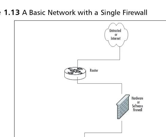
Figure 1.3
IP Packet Header ContentsSo the question remains, “how do IP packets actually get from system to system?” Let’s reference our previous example of browsing to www.syngress.com. When the IP packet is formed, it includes the source IP address (the IP address of the client system making the request).This is like the return address on an envelope that tells the recipient where to send return mail to.The packet also receives the destination address of the Web server being con-tacted.There are other parts that are set in the IP header, but are not germane to this discus-sion. After the packet is created, it is sent to the originating system’s routing table.The routing table is referenced and then the operating system determines which path to send this packet to. In routing, each system that receives the packet determines the next location or
hop to send the packet to. So when sending information or requests across the Internet, there may be 15 hops or routers to go through before you get to the final system you are trying to connect to. Simply stated, a router is a system whose primary function is to route traffic from one location to another. As each router receives a packet, it determines the next best location to send it to.
This, of course, is very simplified since there are millions of routers on the Internet. Once the destination system receives the IP packet, it formulates a response.This is then sent back to the client system.The IP header contains the source address of the server that received the first packet and then the destination address of the initiating client machine. This is the fundamental basis of IP communications.
One of the confusing things about IP is that IP packets are not just used to transport data; the IP protocol suite does more than that. If you refer back to Table 1.1, you can see a field called protocol.This determines which IP protocol the packet is using. All of the available IP protocols are specified in RFC 1700.Table 1.1 is a short reference of the IP protocols we will be discussing in this book. For example, if the packet was UDP, it would be using IP protocol 17, and if the packet was IP Security (IPSec) ESP, it would be using IP protocol 50.
F rag m e n t (3 b its )
Id e n tific atio n T ag (16 b its )
L e n g th (16 b its ) T yp e o f S e rvic e
(8 b its ) IP H e ad e r L e n g th
(4 b its ) V e rs io n
(4b its )
F rag m e n t o ffs e t
(13 b its ) T im e to L ive(8 b its ) P ro to c o l(8 b its ) H e ad e r C h e c ks u m(16 b its ) D e s tin atio n IP ad d re s s
(32 b its ) S o u rc e IP ad d re s s
Table 1.1 IP Protocol Suite
Protocol Number Name Protocol
1 ICMP Internet Control Message Protocol 4 IP IP to IP Encapsulation
6 TCP Transmission Control Protocol 17 UDP User Datagram Protocol 50 ESP Encapsulating Security Payload 51 AH Authentication Header
One of the most important protocols in the IP protocol suite is the Internet Control Messaging Protocol (ICMP). ICMP is used as a messaging protocol to give information to the source or destination machine that is engaging in IP communications.Table 1.2 lists all of the commonly used ICMP types and codes.To give an example of ICMP, let’s look at the common application ping. Ping is an application that is on pretty much any operating system, including Screen OS, the underlying security operating system of Juniper NetScreen firewalls. It is used to test if a host is responsive from a network perspective. When you ping a host, an IP packet is generated that has the source IP address of the requesting system, and the destina-tion IP address of the system you are trying to contact.This packet then has an ICMP type of eight and a code of zero.The destination system then would receive the packet and recognize that the IP packet is echo or echo request packet. It then creates an ICMP packet that is a type zero code zero.This is an echo reply packet, acknowledging the original request.
Table 1.2
ICMP Types and CodesType Name
0 Echo Reply
Codes Name
0 No Code
Type Name
3 Destination Unreachable
Codes Name
Devices use ICMP for other reasons as well. If a system had a route in its routing table that specified a host could be found at a location that did not exist, the router it points to would send an ICMP message to the initiating host.That router would send a type three code zero or code one message specifying that the network or host is not available. Now apply that to the Internet and all of those millions of routers out there.This makes the ICMP protocol very helpful for notifying users when there is a problem with getting IP packets from one location to another.
What Does an IP Address Look Like?
IP addresses are 32 bits in length.They consist of four eight-bit numbers. An example of an IP address is 1.2.3.4.This looks like a very simple format, but it has a great deal of meaning. Each of the four numbers can contain a value from 0 to 255. IP addresses are allocated in blocks or subnets. A subnet is a grouping of IP addresses based upon a subnet mask.There are three major types of IP address blocks: class A, B, and C. Each class is determined based upon the three leading bits for each number.The class A grouping of IP addresses all start with the binary digit 0.The class B grouping of IP addresses all start with binary digits 10 (not read as ten). Finally, the class C grouping of IP addresses all starts with binary digits 110 (not read as one-hundred ten). In Table 1.3 you can see all of the ranges of IP addresses based upon class.There are two other classes of IP addresses, classes D and E, which have special functions not covered in this book.
Table 1.3
IP Address Ranges by ClassClass Address Range
A 0.0.0.0 to 127.255.255.255 B 128.0.0.0 to 191.255.255.255 C 192.0.0.0 to 223.255.255.255 D 224.0.0.0 to 239.255.255.255 E 240.0.0.0 to 255.255.255.255
Figure 1.4
Microsoft Windows ipconfigOutputFigure 1.5
UNIX ifconfigOutputIP Address Allocation
When creating a network, deciding on IP address allocation is very important. But with bil-lions of options, how does one decide? The Internet Assigned Numbers Authority, or IANA, is responsible for allocating IP addresses.They determine which organizations get which IP address ranges.They are also responsible for conserving IP addresses and planning for future uses for IP addresses. Does this mean you need to contact them to get IP addresses? Unless you are starting your own Internet service provider (ISP) the size of Qwest or SBC, you do not need to contact them.Your ISP will always assign any Internet or public IP addresses, and for private IP address networks you would use the IP addresses specified in RFC 1918. See Table 1.4 for a list of the private IP address ranges. A non-Internet routable IP is an IP address that is not routed on the Internet. If a packet was to leave your network with a source or destination IP address in one of these ranges, it might be dropped by an ISP fire-wall or router. Even if it did make it to the remote network, the machine on that side would not be able to route the traffic back to the private IP address which the packet came from because it is not unique and not publicly routable.
Table 1.4
RFC 1918 IP Address RangesClass Address Range
NAT and Private IP Addresses
Most companies need to access Internet resources while preserving Internet IP addresses. The solution is Network Address Translation, or NAT. NAT is used to hide your private IP address behind a public IP address.This allows private IP-addressed systems to access publicly addressed systems. NAT also provides a layer of security by hiding the real IP addresses of your internal network. A gateway device such as a Juniper NetScreen firewall performs NAT for IP packets that pass through the device. Once the firewall receives an IP packet with the source IP address, it changes the private IP address into a public IP address. When the Juniper NetScreen firewall receives the return packet, it translates the new destination address to the private IP address.Two types of NAT exist: NAT source and NAT destination.
TCP Communications
The Transmission Control Protocol is used to control the creation and form of data transfer connections.TCP is one of two transport layer protocols used as part of the TCP/IP pro-tocol suite.TCP is designed to provide many functions, mostly based on reliability.TCP is used for applications that require reliability over speed. When talking about speed at this level, we are talking about calculations of milliseconds or less.TCP functions as a stateful protocol.This means that during the communications, the connection has specific states in which it functions.There is a clear beginning, middle, and end to a TCP connection.
When a TCP session begins, it goes through a three-way handshaking process. Inside of a TCP header, options (called flags) are set.These flags identify the type of TCP message that has been sent.The three-way handshake process is shown in Figure 1.6. Let’s continue to use our earlier example of employing your Web browser to access www.syngress.com. When your Web browser attempts to make its connection to the Web server, it attempts to open a connection to TCP port 80. A port is a particular communications channel specific to a par-ticular application.TCP port 80 is the default port for HTTP.
Figure 1.6
TCP Session Initialization`
SYN Example of a Three-Way Handshake for a TCP Session
Initialization
Client Server SYN ACK
The first packet that is sent to the Web server is a SYN packet, which is used to syn-chronize a connection between two hosts.This packet is also sent with a sequence number that is used to identify the packet inside of this connection.This sequence number is to be used for the initiating systems packets. Next, the Web server that receives the packet acknowledges it.To do this, the server creates and sends a packet with the TCP flags SYN and ACK. A packet that has the ACK (or acknowledgement) flag set is sending a message to the other system that says, “I have received your packet.” A sequence number is also given to this packet that is independent of the sequence number associated with the initiating system’s sequence number.The system that initiated the connection now sends an ACK packet to acknowledge the connection.The ACK packet has a sequence number that is incremented since it is the second packet that has been sent from this system.The TCP session has now been created and the requested data from the Web server can begin to pass to the client.
The data that was requested is divided into packets by TCP.The client sends a TCP packet with the ACK flag for each part of the data. Again, each packet sent from the client has a sequence number that is incremented by one.The sequence number is used to identify all of the packets of a TCP exchange. If, for example, a client receives packets with sequence numbers 6, 7, 8, and 10, but never receives packet 9, the client will request that packet 9 be re-sent from the server. On the client, all of the packets would be reordered before passing the data back to the application. When the connection is completed, the server system would send a packet with the FIN flag.This indicates that the connection is finished.The client would then send an ACK packet back to the server acknowledging that the conversa-tion has completed.
UDP Communications
The User Datagram Protocol is a connectionless protocol that is designed to stream data. When a UDP connection occurs, there is no beginning, middle, or end to the conversation. Data simply begins to flow between the two systems. UDP is a very simple protocol and is used when speed is an issue. UDP packet receipt is not verified. An example of a use of the UDP protocol is DNS queries. When you attempt to use your Web browser to access www.syngress.com, it must first resolve the name to an IP address.This would require a DNS query.The query is sent over a single UDP packet.The DNS server would then respond by telling the originating system the IP address of the Web server. Because the UDP response is faster than setting up a TCP session, UDP makes sense in these situations. Another example of using UDP is Voice over IP (VoIP).The downfall, of course, is the lack of reliability, so you may have to employ other methods to guarantee delivery.
What Is a Port?
or application. When you tune to that port, you can access those specific resources. Theoretically, you can put any application on any port, but by specifying specific ports for specific applications, you can always be assured of the type of content you will find on a spe-cific port.
This is why a specification of known ports has been established.Table 1.5 lists well-known TCP and UDP ports. Using our earlier television example, this is much like a channel lineup. If television programming could appear on any television channel, there would be a lot of confusion about which programming you were watching. When you use your television, the service provider gives you a channel lineup.This lineup is specified so that you know which channel is which. Most Web servers serve data over port 80. Again, they can serve the data over any port, but it would be very hard to get the content if you did not know which port to use.
Table 1.5
Well-Known TCP and UDP PortsWell-Known TCP Ports Well-Known UDP Ports
FTP 21 DNS 53
SSH 22 DHCP-Relay 67 Telnet 23 TFTP 69 SMTP 25 NTP 123 HTTP 80 IKE 500 IMAP 143 Syslog 514 HTTPS 443 H.323 1719
Data Link Layer Communication
The last part of networking we are going to discuss is the data link layer, or layer two.This layer is essentially the protocol that operates on the specific physical medium. Each of the following function differently on the data link layer: Ethernet, ATM, Frame Relay, HDLC, SDLC, PPP, and Serial Line Internet Protocol (SLIP) to name a few. In this section how Ethernet functions will be focused on. As of the time of this writing the main layer two pro-tocol that is used by NetScreen firewalls is Ethernet.
manufacturer is assigned a range to use when creating Ethernet adapters.Then each indi-vidual adapter is given a unique number to create the MAC address.
Figure 1.7
A Layered Look at Network CommunicationsBecause systems communicate via IP, but need to talk over Ethernet (which requires the use of MAC addresses), there has to be a way to resolve an IP to a MAC address.The method used is called the Address Resolution Protocol. For example, if system A, which has an IP address of 192.168.1.10, wanted to view the Web pages on system B, which has an IP address of 192.168.1.25, before the communications can begin, system A must learn the MAC address of system B. System A broadcasts a request over the local broadcast domain asking who has the IP address 192.168.1.25. A broadcast is a communication that is sent out to every system that is within a broadcast area. All of the systems in the broadcast area get this request and the system with the requested IP address responds with a unicast message that specifies it has the IP address of 192.168.1.25 and also provides its MAC address.
are isolated and the switch prevents packets from colliding. If a system was to broadcast, however, the broadcast would be sent to every system connected to the switch. When the switch sends the data between two hosts, it sends it in such a way that other network con-versations are not interrupted.
Understanding Security Basics
The first key to understanding network security is to understand networking. We hope, the previous section has started you on the path to understand networking. Just be patient while reading this book.There may be many new concepts you have never heard of before. Working with these technologies over time will help solidify your knowledge.You can also reach for other Syngress Publishing books on the topic of information security (infosec) that can help build on your body of knowledge. In this section, we discuss basic security concepts that will prepare you for the final section about firewalls, and focus on some of the different aspects of what it takes to have a secure organization. As you will see, there are no hard and fast rules about what it really takes to make your network secure. I have been to many orga-nizations that would fall well below the line I would call good security practices. However, some of those same organizations have gone years without a security breach. On the other hand, I have seen other companies spend much more on their security and have more prob-lems with break-ins and data loss.
The Need for Security
Enterprise security is the hottest technology trend today. Every aspect of a company’s data infrastructure has a need for security. With ever-growing, ever-evolving networks in all orga-nizations, managing security has become harder. For many companies, the operating budget for security is less than one percent of their total budget. When it comes down to purchasing security products, firewalls are the core product used to secure the enterprise network. However, firewalls should by no means be the only method used to secure your network, but if used effectively, they can mitigate the risks of network security breaches and data loss. With integrated technologies such as antivirus software, deep packet inspection, Uniform Resource Locator (URL) filtering, and virtual private networks (VPNs), the firewall can provide a host of security applications all in one system. Nevertheless, as the old saying goes, never put all your eggs in one basket.
Introducing Common Security Standards
capa-bility, and the training of users and technicians to maintain the security and integrity of the data.These constraints do not relieve us of our responsibility of maintaining the data safely and securely.To that end, we currently employ some accepted standards for security that help us perform our tasks to the best possible level. In this section, we remind you of the
common security standards and briefly discuss them:
■ Authentication, authorization, and auditing (AAA) AAA use is required in security operations for creating and maintaining the method of authenticating users and processes, and validating their credentials prior to allowing access to resources. It is also the method we use to grant access or deny access to the resource. Auditing of activity is a crucial part of this function.
■ Confidentiality, integrity, and availability (CIA) CIA is the originally defined process that establishes the goals we have used to try to protect our data from unauthorized view, corruption, or unauthorized modification, and to provide constant availability. Over the past few years, the CIA processes have expanded to include a more comprehensive guideline that also includes the process of defining risk and use of risk management tools to provide a more complete method of pro-tection.
■ Least privilege This concept is used by the security planners and teams to define the levels of access to resources and the network that should be allowed. From a security standpoint, it is always preferable to be too restrictive with the capability to relax the access levels than to be too loose and have a breach occur.
Remember, too, that the security process involves a three-tiered model for security protection:
■ Computer security, including the use of risk assessment, the expanded CIA goals, and enterprise planning that extends throughout the entire enterprise, rather than to just a portion of it.
■ Physical security, in which we must build and include physical access systems and coordinate them with our network access systems.
■ Trusted users, who become an important cog in maintaining the integrity of our security efforts.
Common Information Security Concepts
A generic dictionary definition of security (taken from the American Heritage Dictionary) is, “freedom from risk or danger; safety.”This definition is perhaps a little misleading when it comes to computer and networking security, because it implies a degree of protection that is inherently impossible to achieve in the modern connectivity-oriented computing
For this reason, the same dictionary provides another definition specific to computer sci-ence: “The level to which a program or device is safe from unauthorized use” (emphasis added). Implicit in this definition is the caveat that the objectives of security and accessi-bility—the two top priorities on the minds of many network administrators—are, by their very nature, diametrically opposed.The more accessible your data, the less secure it is. Likewise, the more tightly you secure your data, the more you impede accessibility. Any security plan is an attempt to strike the proper balance between the two.
Defining Information Security
Over the last couple of decades, many companies began to realize that their most valuable assets were not only their buildings or factories but also intellectual property (Known as IP in the industry) and other key business information. Company managers, who are used to dealing with risk in their business activities, started to worry about what might happen if this information fell into the wrong hands, perhaps a competitor’s. In addition, the Sarbanes-Oxley Act of 2002 (a.k.a. SOX or SARBOX) generally legislated IT governance and controls, thrusting information security to the front stage in publicly traded companies
For a while, this risk was not too large, due to how and where that information was stored.Closed systemswas the operative phrase. Key business information, for the most part, was stored on servers accessed via terminals or terminal emulators and had few interconnec-tions with other systems. Any interconnecinterconnec-tions tended to be over private leased lines to a select few locations, either internal to the company or to a trusted business partner.
However, over the last five to seven years, the Internet has changed how businesses operate, and there has been a huge acceleration in the interconnectedness of organizations, systems, and networks. Entire corporate networks have access to the Internet, often at mul-tiple points.This proliferation has created risks to sensitive information and business-critical systems where they had barely existed before.The importance of information security in the business environment has now been underscored, as has the need for skilled, dedicated prac-titioners of this specialty.
We have traditionally thought of security as consisting of people, sometimes with guns, watching over and guarding tangible assets such as a stack of money or a research lab. Maybe they sat at a desk and watched via closed-circuit cameras installed around the property.These people usually had minimal training and sometimes did not understand much about what they were guarding or why it was important. However, they did their jobs (and continue to do so) according to established processes, such as walking around the facility on a regular basis and looking for suspicious activity or people who do not appear to belong there.
Information security moves that model into the intangible realm. Fundamentally, infor-mation security involves making sure that only authorized people (and systems) have access to information. Information security professionals sometimes have different views on the role and definition of information security.
■ Confidentiality Ensuring that only authorized parties have access to informa-tion. Encryption is a commonly used tool to achieve confidentiality.
Authentication and authorization, treated separately in the following discussion, also help with confidentiality.
■ Integrity Ensuring that information is not modified by unauthorized parties (or even improperly modified by authorized ones!) and that it can be relied on. Checksums and hashes are used to validate data integrity, as are transaction-logging systems.
■ Availability Ensuring that information is accessible when it is needed. In addi-tion to simple backups of data, availability includes ensuring that systems remain accessible in the event of a Denial-of-Service (DoS) attack. Availability also means that critical data should be protected from erasure—for example, preventing the wipeout of data on your company’s external Web site.
Often referred to simply by the acronym CIA, these three areas serve well as a security foundation.To fully scope the role of information security, however, we also need to add a few more areas of concern to the list. Some security practitioners include the following within the three areas previously described, but by getting more granular, we can get a better sense of the challenges that must be addressed:
■ Authentication Ensuring that users are, in fact, who they say they are. Passwords, of course, are the longstanding way to authenticate users, but other methods such as cryptographic tokens and biometrics are also used.
■ Authorization/access control Ensuring that a user, once authenticated, is only able to access information to which he or she has been granted permission by the owner of the information.This can be accomplished at the operating-system level using file system access controls, or at the network level using access controls on routers or firewalls.
■ Audit capability Ensuring that activity and transactions on a system or network can be monitored and logged in order to maintain system availability and detect unauthorized use.This process can take various forms: logging by the operating system, logging by a network device such as a router or firewall, or logging by an intrusion detection system (IDS) or packet-capture device.
■ Nonrepudiation Ensuring that a person initiating a transaction is authenticated sufficiently such that he or she cannot reasonably deny that they were the initi-ating party. Public key cryptography is often used to support this effort.
Insecurity and the Internet
The federation of networks that became the Internet consisted of a relatively small commu-nity of users by the 1980s, primarily in the research and academic communities. Because it was rather difficult to get access to these systems and the user communities were rather closely knit, security was not much of a concern in this environment.The main objective of connecting these various networks together was to share information, not keep it locked away.Technologies such as the UNIX operating system and the TCP/IP networking proto-cols that were designed for this environment reflected this lack of security concern. Security was simply viewed as unnecessary.
By the early 1990s, however, commercial interest in the Internet grew.These commercial interests had very different perspectives on security, ones often in opposition to those of academia. Commercial information had value, and access to it had to be limited to specifi-cally authorized people. UNIX,TCP/IP, and connections to the Internet became avenues of attack and did not have much capability to implement and enforce confidentiality, integrity, and availability. As the Internet grew in commercial importance, with numerous companies connecting to it and even building entire business models around it, the need for increased security became quite acute. Connected organizations now faced threats that they had never had to consider before.
When the corporate computing environment was a closed and limited-access system, threats mostly came from inside the organizations.These internal threatscame from disgrun-tled employees with privileged access who could cause a lot of damage. Attacks from the outside were not much of an issue since there were typically only a few, if any, private con-nections to trusted entities. Potential attackers were few in number, since the combination of necessary skills and malicious intent were not at all widespread.
With the growth of the Internet,external threatsgrew as well.There are now millions of hosts on the Internet as potential attack targets, which entice the now large numbers of attackers.This group has grown in size and skill over the years as its members share informa-tion on how to break into systems for both fun and profit. Geography no longer serves as an obstacle, either.You can be attacked from another continent thousands of miles away just as easily as from your own town.
Threats can be classified as structured or unstructured.Unstructured threatsare from people with low skill and perseverance.These usually come from people called script
Structured attacksare more worrisome because they are conducted by hackers with signif-icant skill. If the existing tools do not work for them, they are likely to modify them or write their own.They are able to discover new vulnerabilities in systems by executing com-plex actions that the system designers did not protect against. Structured attackers often use so-called zero-day exploits, which are exploits that target vulnerabilities that the system vendor has not yet issued a patch for or does not even know about. Structured attacks often have stronger motivations behind them than simple mischief.These motivations or goals can include theft of source code, theft of credit card numbers for resale or fraud, retribution, or destruction or disruption of a competitor. A structured attack might not be blocked by tradi-tional methods such as firewall rules, or be detected by an IDS. It could even use non-com-puter methods such as social engineering.
N
OTESocial engineering, also known as people hacking, is a means of obtaining secu-rity information from people by tricking them. The classic example is calling up a user and pretending to be a system administrator. The hacker asks the user for his or her password to ostensibly perform some important maintenance task. To avoid being hacked via social engineering, educate your user community that they should always confirm the identity of any person calling them and that passwords should never be given to anyoneover e-mail, instant messaging, or the phone.
Another key task in securing your systems is closing vulnerabilities by turning off unneeded services and bringing them up-to-date on patches. Services that have no defined business need present an additional possible avenue of attack and are just another component that needs patch attention. Keeping patches current is actually one of the most important activities you can perform to protect yourself, yet it is one that many organizations neglect.
The Code Red and Nimda worms of 2001 were successful primarily because so many systems had not been patched for the vulnerabilities they exploited, including multiple Microsoft Internet Information Server (IIS) and Microsoft Outlook vulnerabilities. Patching, especially when you have hundreds or even thousands of systems, can be a monumental task. However, by defining and documenting processes, using tools to assist in configuration man-agement, subscribing to multiple vulnerability alert mailing lists, and prioritizing patches according to criticality, you can get a better handle on the job.
One useful document to assist in this process has been published by the U.S. National Institute of Standards and Technology (NIST), which can be found at http://csrc.nist.gov/ publications/nistpubs/800-40/sp800-40.pdf (800-40 is the document number).
you define different zones of trust and highlights where re-architecting the network in places might improve security—for example, by deploying additional firewalls internally or on your network perimeter.
Identifying Potential Threats
As you prepare your overall security plan and demilitarized zone (DMZ), it is important that you identify and evaluate the potential risks and threats to your network, systems, and data. You must evaluate your risks thoroughly during the identification process to assign some sort of value to the risks in order to determine priorities for protection and likelihood of loss resulting from those risks and threats if they materialize. In this vein, you should be looking at and establishing a risk evaluation for anything that could potentially disrupt, slow, or damage your systems, data, or credibility. In this area, it is important to assign these values to potential threats such as:
■ Outside hacker attacks
■ Trojans, worms, and virus attacks
■ DoS or Distributed Denial-of-Service (DDoS) attacks
■ Compromise or loss of internal confidential information
■ Network monitoring and data interception
■ Internal attacks by employees
■ Hardware failures
■ Loss of critical systems
This identification process creates the basis for your security plan, policies, and imple-mentation of your security environment.You should realize that this is an ongoing evaluation that is subject to change as conditions within your company and partners (as well as the employee need for access) change and morph over time. We have learned that security is a process and is never truly “finished.” However, a good basic evaluation goes a long way toward creating the most secure system we can achieve.