Report Number: C4-040R-02
Router Security
Configuration Guide
Principles and guidance for secure configuration of IP routers,
with detailed instructions for Cisco Systems routers
Router Security Guidance Activity
of the
System and Network Attack Center (SNAC)
Authors:
Vanessa Antoine Raymond Bongiorni Anthony Borza Patricia Bosmajian Daniel Duesterhaus Michael Dransfield Brian Eppinger Kevin Gallicchio Stephen Hamilton James Houser Andrew Kim Phyllis Lee Brian McNamara Tom Miller David Opitz Florence Richburg Michael Wiacek Mark Wilson Neal Ziring
December 15, 2005 Version: 1.1c
National Security Agency
9800 Savage Rd. Suite 6704
Ft. Meade, MD 20755-6704
Warnings
This document is only a guide to recommended security settings for Internet Protocol (IP) routers, particularly routers running Cisco Systems Internet Operating System (IOS) versions 11.3 through 12.4. It cannot replace well-designed policy or sound judgment. This guide does not address site-specific configuration issues. Care must be taken when implementing the security steps specified in this guide. Ensure that all security steps and procedures chosen from this guide are thoroughly tested and reviewed prior to imposing them on an operational network.
SOFTWARE IS PROVIDED "AS IS" AND ANY EXPRESS OR IMPLIED WARRANTIES, INCLUDING, BUT NOT LIMITED TO, THE IMPLIED
WARRANTIES OF MERCHANTABILITY AND FITNESS FOR A PARTICULAR PURPOSE ARE EXPRESSLY DISCLAIMED. IN NO EVENT SHALL THE CONTRIBUTORS BE LIABLE FOR ANY DIRECT, INDIRECT, INCIDENTAL, SPECIAL, EXEMPLARY, OR CONSEQUENTIAL DAMAGES (INCLUDING, BUT NOT LIMITED TO, PROCUREMENT OF SUBSTITUTE GOODS OR SERVICES; LOSS OF USE, DATA, OR PROFITS; OR BUSINESS INTERRUPTION) HOWEVER CAUSED AND ON ANY THEORY OF LIABILITY, WHETHER IN CONTRACT, STRICT LIABILITY, OR TORT (INCLUDING NEGLIGENCE OR OTHERWISE) ARISING IN ANY WAY OUT OF THE USE OF THIS SOFTWARE, EVEN IF ADVISED OF THE POSSIBILITY OF SUCH DAMAGE.
This document is current as of October, 2005. The most recent version of this document may always be obtained through http://www.nsa.gov/.
Acknowledgements
The authors would like to acknowledge Daniel Duesterhaus, author of the original NSA “Cisco Router Security Configuration Guide,” and the management and staff of the Applications and Architectures division for their patience and assistance with the initial development of this guide. Special thanks also go to Ray Bongiorni for quality assurance and editorial work, and to Julie Martz and Kathy Jones for proof-reading assistance. Additional contributors to the guide effort include Andrew Dorsett, Charles Hall, Scott McKay, and Jeffrey Thomas. Thanks must also be given to the dozens of professionals outside NSA who made suggestions for the improvement of this document, especially George Jones, John Stewart, and Joshua Wright.
Trademark Information
Cisco, IOS, and CiscoSecure are registered trademarks of Cisco Systems, Inc. in the USA and other countries. Windows 2000 and Windows XP are registered trademarks of Microsoft Corporation in the USA and other countries. All other names are trademarks or registered trademarks of their respective companies.
Revision History
1.0 Sep 2000 First complete draft, extensive internal review. 1.0b Oct 2000 Revised after review by Ray Bongiorni 1.0f Mar 2001 Second release version: second pre-pub review 1.0g Apr 2001 Third release version: incorporated external feedback. 1.0h Aug 2001 Fourth release version; another QA review.
1.0j Nov 2001 Fifth release version.
1.0k Mar 2002 Last release of 1.0, another pre-pub review.
Contents
Contents
Preface 5
1. Introduction 7
1.1. The Roles of Routers in Modern Networks ...7
1.2. Motivations for Providing Router Security Guidance...9
1.3. Typographic and Diagrammatic Conventions Used in this Guide ...10
1.4. Structural Overview ...12
2. Background and Review 15 2.1. Review of TCP/IP Networking ...15
2.2. TCP/IP and the OSI Model ...17
2.3. Review of IP Routing and IP Architectures ...19
2.4. Basic Router Functional Architecture ...24
2.5. Review of Router-Relevant Protocols and Layers ...27
2.6. Quick “Review” of Attacks on Routers ...29
2.7. References...30
3. Router Security Principles and Goals 33 3.1. Protecting the Router Itself ...33
3.2. Protecting the Network with the Router...35
3.3. Managing the Router...43
3.4. Security Policy for Routers ...46
3.5. References...51
4. Implementing Security on Cisco Routers 54 4.1. Router Access Security ...55
4.2. Router Network Service Security...70
4.3. Access Control Lists, Filtering, and Rate Limiting...83
4.4. Routing and Routing Protocols ...102
4.5. Audit and Management...139
4.6. Security for Router Network Access Services ...175
4.7. Collected References...202
5. Advanced Security Services 204 5.1. Role of the Router in Inter-Network Security...204
5.2. IP Network Security...205
5.3. Using SSH for Remote Administration Security ...227
5.4. Using a Cisco Router as a Firewall ...232
5.5. Cisco IOS Intrusion Detection ...241
5.6. References...247
6.1. Principles for Router Security Testing ...250
6.2. Testing Tools...250
6.3. Testing and Security Analysis Techniques ...251
6.4. Using the Router Audit Tool...258
6.5. References...261
7. Additional Issues in Router Security 263 7.1. Routing and Switching...263
7.2. IPv6 ...265
7.3. ATM and IP Routing...266
7.4. Multi-Protocol Label Switching (MPLS)...267
7.5. IPSec and Dynamic Virtual Private Networks ...268
7.6. Tunneling Protocols and Virtual Network Applications ...269
7.7. IP Quality of Service (QoS) and RSVP...270
7.8. Secure DNS...271
7.9. References...272
8. Appendices 274 8.1. Top Ways to Quickly Improve the Security of a Cisco Router...274
8.2. Application to Ethernet Switches and Related Non-Router Network Hardware...280
8.3. Overview of Cisco IOS Versions and Releases ...283
8.4. Glossary of Router Security-related Terms...289
9. Additional Resources 295 9.1. Bibliography...295
9.2. Web Site References ...298
Preface
Preface
Routers direct and control much of the data flowing across computer networks. This guide provides technical guidance intended to help network administrators and security officers improve the security of their networks. Using the information presented here, you can configure your routers to control access, resist attacks, shield other network components, and protect the integrity and confidentiality of network traffic.
This guide was developed in response to numerous questions and requests for assistance received by the NSA System and Network Attack Center (SNAC). The topics covered in the guide were selected on the basis of customer interest,
community concensus, and the SNAC’s background in securing networks.
The goal for this guide is a simple one: improve the security provided by routers in US Government operational networks.
Who Should Use This Guide
Network administrators and network security officers are the primary audience for this configuration guide, throughout the text the familiar pronoun “you” is used for guidance directed specifically to them. Most network administrators are responsible for managing the connections within their networks, and between their network and various other networks. Network security officers are usually responsible for selecting and deploying the assurance measures applied to their networks. For this audience, this guide provides security goals and guidance, along with specific examples of configuring Cisco routers to meet those goals.
Firewall administrators are another intended audience for this guide. Often, firewalls are employed in conjunction with filtering routers; the overall perimeter security of an enclave benefits when the configurations of the firewall and router are
complementary. While this guide does not discuss general firewall topics in any depth, it does provide information that firewall administrators need to configure their routers to actively support their perimeter security policies. Section 5 includes information on using the firewall features of the Cisco Integrated Security facility.
Information System Security Engineers (ISSEs) may also find this guide useful. Using it, an ISSE can gain greater familiarity with security services that routers can provide, and use that knowledge to incorporate routers more effectively into the secure network configurations that they design.
Feedback
Introduction
1.
Introduction
1.1.
The Roles of Routers in Modern Networks
On a very small computer network, it is feasible to use simple broadcast or sequential mechanisms for moving data from point to point. An Ethernet local area network (LAN) is essentially a broadcast network. In larger, more complex networks, data must be directed specifically to the intended destination. Routers direct network data messages, or packets, based on internal addresses and tables of routes, or known destinations that serve certain addresses. Directing data between portions of a network is the primary purpose of a router.
Most large computer networks use the TCP/IP protocol suite. See Section 2.3 for a quick review of TCP/IP and IP addressing. Figure 1-1, below, illustrates the primary function of a router in a small IP network.
Router 2
File Server 14.2.9.10 Router 1
User Host 190.20.2.12
Wide Area Network
LAN 2
14.2.6.0 LAN 3
14.2.9.0 LAN 1
[image:7.612.180.482.314.525.2]190.20.2.0
Figure 1-1 – A Simple Network with Two Routers
Introduction
1.2.
Motivations for Providing Router Security Guidance
Routers provide services that are essential to the correct, secure operation of the networks they serve. Compromise of a router can lead to various security problems on the network served by that router, or even other networks with which that router communicates.
• Compromise of a router’s route tables can result in reduced performance, denial of network communication services, and exposure of sensitive data. • Compromise of a router’s access control can result in exposure of network configuration details or denial of service, and can facilitate attacks against other network components.
• A poor router filtering configuration can reduce the overall security of an entire enclave, expose internal network components to scans and attacks, and make it easier for attackers to avoid detection.
• On the other hand, proper use of router cryptographic security features can help protect sensitive data, ensure data integrity, and facilitate secure cooperation between independent enclaves.
In general, well-configured secure routers can greatly improve the overall security posture of a network. Security policy enforced at a router is difficult for negligent or malicious end-users to circumvent, thus avoiding a very serious potential source of security problems.
There are substantial security resources available from router vendors. For example, Cisco offers extensive on-line documentation and printed books about the security features supported by their products. These books and papers are valuable, but they are not sufficient. Most vendor-supplied router security documents are focused on documenting all of the security features offered by the router, and do not always supply security rationale for selecting and applying those features. This guide attempts to provide security rationale and concrete security direction, with pertinent references at the end of each section identifying the most useful vendor
1.3.
Typographic and Diagrammatic Conventions Used in this Guide
To help make this guide more practical, most of the sections include extensive instructions and examples. The following typographic conventions are used as part of presenting the examples.
• Specific router and host commands are identified in the text using Courier bold typeface: “to list the current routing table, use the command show ip
route.” Command arguments are shown in Courier italics: “syntax for a
simple IP access list rule is access-list number permit host
address.”
• Sequences of commands to be used in a configuration are shown separately from the text, using Courier typeface. The exclamation point begins a comment line, usually a remark about the line that follows it.
! set the log host IP address and buffer size
logging 14.2.9.6
logging buffered 16000
• Transcripts of router sessions are shown separately from the text, using Courier typeface. Input in the transcript is distinguished from output, user input and comments are shown in Courier bold typeface. Elision of long output is denoted by two dots. In some cases, output that would be too wide to fit on the page is shown with some white space removed, to make it narrower.
Central> enable Password:
Central# ! list interfaces in concise format Central# show ip interface brief
Interface IP Address OK? Method
Ethernet 0/0 14.2.15.250 YES NVRAM
Ethernet 0/1 14.2.9.250 YES Manual
. .
Central# exit
• IP addresses will be shown in the text and in diagrams as A.B.C.D, or as A.B.C.D/N, where N is the number of set bits in the IP netmask. For example, 14.2.9.150/24 has a netmask of 255.255.255.0. (In general, this classless netmask notation will be used where a netmask is relevant. Otherwise, the bare address will be used.)
• Cisco IOS accepts the shortest unique, unambiguous abbreviation for any command or keyword. For commands that are typed very frequently, this guide uses many abbreviations commonly employed in the Cisco
documentation and literature. For example, the interface name ethernet
is commonly abbreviated “eth” and the command configure terminal
Introduction
• In a few cases, commands shown in examples are too long to fit on one line; they are shown broken across several lines. The IOS command line interface will not permit this; when attempting to apply these examples, you will need to type the long command on one line.
Discussions of network structure and security frequently depend on network diagrams. This guide uses the following set of icons in all of its diagrams.
Router2
This icon represents a router. Each line connected to a router icon represents a network interface on that router. Each router is presumed to have an administrative console line connection, which is not shown.
Server Workstation
Computers on the network are represented with one of these two icons.
Small LAN 12.34.56.0/24
A local-area network (LAN) segment, such as an Ethernet, is represented by a horizontal or vertical bus, with several connections.
Network
1.4.
Structural Overview
The various parts of this guide are designed to be fairly independent; readers may want to skip directly to the sections most immediately useful to them. The list below describes the major sections. References are included at the end of each section.
• Section 2 reviews some background information about TCP/IP networking and network security, and describes some simple network security threats. • Section 3 presents a security model for routers, and defines general goals
and mechanisms for securing routers. Security mechanisms must be applied in support of security policy; this section describes some areas that a router security policy should address, along with a discussion of
relationships between router security and overall network security. • Section 4 details the methods and commands for applying security to
Cisco routers, using recent versions of the Cisco IOS software. It is divided into six main parts:
• securing access to the router itself, • securing router network services,
• controlling traffic and filtering using a router, • configuring routing protocols security, • security management for routers, and • network access control for routers.
• Section 5 describes advanced security services that some routers can provide, with a focus on Cisco routers’ capabilities. The main topics of this section are IP security (IPSec), Secure Shell (SSH), and using a Cisco router as a simple firewall and Intrusion Detection System (IDS).
• Section 6 presents testing and troubleshooting techniques for router security. It is essential for good security that any router security configuration undergoes testing, and this section presents both vendor-independent and Cisco-specific testing techniques.
• Section 7 previews some security topics that are not yet crucial for router configuration, but which may become important in the near future. • Section 8 consists of four diverse appendices:
• tips for quickly improving the security of a router • how to apply parts of this guide to LAN switches
• overview of the Cisco IOS software family and versions, and • a router security glossary.
Introduction
How to Use This Guide
Several different roles are involved in securing a network, and each may need some information about router security. The paragraphs below offer roadmaps for using this guide for several different network security roles.
For network security planners and system security designers, the high-level view of router security is more important than the details of Cisco router commands. Read the sections listed below if your role is security planner or security designer.
• Section 2 – for a review of TCP/IP, network, and router operational concepts
• Section 3 – for general router security principles
• Section 4.1 through 4.3 – for an idea of what Cisco routers can do for network security
• Section 5 – for information about Cisco router VPN, firewall, and other advanced security capabilities
• Section 7 – for a preview of potential future issues
For network administrators involved in the daily operation of a network with Cisco routers, the detailed instructions for locking down a router are the most important part of this guide. Read the sections listed below if your role is network
administrator.
• Section 2 – for a review, if necessary
• Section 3 – for the security principles behind the advice in Section 4 • Section 4 – for detailed instructions on configuring Cisco routers • Section 5.1, 5.2 – for instructions on configuring IPSec on Cisco
routers
• Section 5.3 – for a quick guide to using SSH for Cisco administration • Section 8.1 – for advice for quickly securing a Cisco router
• Section 8.2 – for instructions on applying this guide to LAN switches • Section 8.3 – for information on Cisco IOS versions and upgrades • Section 9 – for an overview of recommended references and tools
For network security analysts or administrators trying to improve the security posture of a network as quickly as possible, this guide offers detailed advice and direction. Read the sections listed below if your goal is to quickly lock down a router.
• Section 8.1 – for quick tips that will greatly improve router security • Section 4.1 – for explicit directions on router access security • Section 4.3 – for advice and guidance on setting up filtering • Section 4.4 – for routing protocol security instructions (unless the
Before applying any of the guidance in this guide to operational routers, be sure to test it thoroughly in a lab or testbed network. Operational networks are complex, and applying configuration changes to a router can instantly affect large numbers of hosts.
Background and Review
2.
Background and Review
This section reviews some background information about TCP/IP networking, router hardware architecture, router software architecture, and network security. In order to keep this section brief, it glosses over a lot of issues. To compensate for that
briefness, the reference list at the end of the section includes a long list of other useful sources of background information. Readers with a good grasp of network and router fundamentals may want to skip this section, but since it is relatively brief, why not humor the author and read on.
2.1.
Review of TCP/IP Networking
As mentioned in Section 1.1, on a small computer network, it is feasible to use simple broadcast or sequential (token) mechanisms for moving data from point to point. A local area network is composed of a relativelysmall number of hosts connected over a relatively small physical area. “Relatively small” is the important phrase here. To give some meaning to the term “relatively,” consider that a 10BaseT Ethernet (10 megabit per second using twisted pair cabling) has a usual maximum of 1024 stations over a maximum cable distance of 2500 meters. For instance, a typical office LAN, using 100BaseT Ethernet, might have 100 computers (and printers) attached to a switch or set of hubs.
An Ethernet local area network (LAN) is essentially a (logical) bus based broadcast network; though the physical implementation may use hubs (with a physical star topology). As one would expect, broadcast LANs must deal with collisions; either by preventing them or detecting them and taking appropriate action. Token based LANs avoid collisions by only allowing one host at time to transmit (the host that currently has the token may transmit).
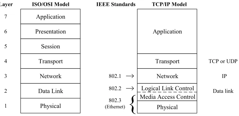
Standards that relate to LANs are primarily the IEEE 802.x series. For instance, 802.3 is the Media Access Control (MAC) standard for CSMA/CD (the Ethernet standard); while 802.5 is the MAC standard for Token Ring. Just above the MAC level is the Logical Link Control (802.2) standard and above that it the High Level Interface (802.1) standard.
Within a LAN, addressing is done with a MAC address. Between LANs using TCP/IP, addressing is done using IP addresses. If you are lost at this point, keep reading because much of this will be explained below. If you are still lost at the end of Section 2, then consider reading parts of some of the books and/or web pages listed at the end of the section.
2.1.1.
Purpose of a Router
network data messages from a LAN and convert them into packets suitable for transmission beyond the LAN on a wide area network (WAN). The goal is almost always to get these packets to another LAN and ultimately to the correct host on that LAN. Part of the “conversion” process is to add a packet header. Other routers will generally only look at a packet’s header information, not at the contents or data in the packet.
Routers also make decisions about where to send these packets, based on: the
addresses contained within the packet headers and a table of routes maintained within the router. Updating these routing tables and forwarding data packets between portions of a network are two of the primary tasks of a router. Building packets and unwrapping packets are additional router functions performed by the first and last routers, respectively, that a message passes through. In addition to directing packets, a router may be responsible for filtering traffic, allowing some packets to pass through and rejecting others. Filtering can be a very important function of routers; it allows them to help protect computers and other network components. For more information about filtering, see Section 3 and Section 4. It is also possible that at the destination end a router may have to break large packets up to accommodate the size limits of the destination LAN.
There is no reason that routers cannot be used to send messages between hosts (as shown in Figure 1-1) but more typically routers are used to connect LANs to each other or to connect a LAN to a WAN.
Most large computer networks use the TCP/IP protocol suite. In some sense this is the lingua franca of the Internet. See Section 2.2 for a quick review of TCP/IP and IP addressing.
2.1.2.
Route Tables
Background and Review
2.2.
TCP/IP and the OSI Model
2.2.1.
Origin of TCP/IP
The Transmission Control Protocol (TCP) and Internet Protocol (IP) comprise what is often seen written as TCP/IP. The Defense Advanced Research Projects Agency (DARPA) originated TCP/IP. Note that the word “Defense” has been deleted and added back over time. ARPA and DARPA are one and the same organization. The National Science Foundation (NSF) also contributed to the foundation of the Internet by taking the DARPA technology and making it available to universities.
As stated above, the Internet essentially runs on TCP/IP protocols. The definitive source for information on TCP/IP are the RFCs, or “Request for Comments” issued by the Internet Engineering Task Force (IETF) as described in Section 2.7.3. Note that in addition to TCP/IP there are other protocols such as Novell’s IPX
(Internetwork Packet eXchange) that can be used with routers. Also, some routers can be used to “translate” between different protocols running on either side of themselves.
2.2.2.
The OSI Model
After TCP/IP was well-established and other networking protocols, such as DECnet and Novell’s IPX were operational, the International Standardization Organization (ISO) developed the Open Systems Interconnection (OSI) seven layer reference model. These seven layers are described in almost every reference, so in the interest of space they are merely enumerated here.
Layer 7: Application Layer -
deals with services such as email and file transfer. Layer 6: Presentation Layer -
deals with formatting, encryption, and compression of data. Layer 5: Session Layer -
deals with setup and management of sessions between applications. Layer 4: Transport Layer -
deals with end to end error recovery and delivery of complete messages. Layer 3: Network Layer -
deals with transmission of packets and establishing connections. Layer 2: Data Link Layer -
deals with transmission of packets on one given physical link. Layer 1: Physical Layer -
deals with transmission of a bit stream and definition of physical link.
OSI model. A collection of various compatible protocol layers is referred to as a stack.
Application
Presentation
Session
Transport
Network
Data Link
Physical
ISO/OSI Model
Application
Transport
Network
TCP/IP Model
Logical Link Control Media Access Control
Physical
IEEE Standards
802.1 802.2 802.3 (Ethernet)
{
TCP or UDP IP 7
6 5 4 3 2 1
Layer
[image:18.612.103.487.132.319.2]Data link
Figure 2-1: Network Layers and Standards
Background and Review
2.3.
Review of IP Routing and IP Architectures
If one is dealing only with a local area network (LAN), there is generally no need for routing, routers, TCP/IP, or IP addresses. Within a LAN everything will be handled by Media Access Control (MAC) addresses and by a LAN protocol such as Ethernet. At this level, most protocols are defined by Institute of Electrical and Electronics Engineers (IEEE) standards. For instance, IEEE 802.3 is the Ethernet (CSMA/CD) standard, 802.4 is token bus, and 802.5 is token ring. Above the MAC standards, but still within the OSI Data Link Layer, is the IEEE 802.2 Logical Link Control standard. The IEEE 802.1 High Level Interface standard corresponds to part of the OSI Network Layer. If this seems confusing, do not worry about it; it’s not essential to an understanding of routers.
What is important to keep in mind is that MAC addresses are used within a LAN. Each device on the LAN will have a something like a network interface card (NIC) which has a unique MAC address. For example, on an Ethernet LAN each device has an appropriate Ethernet card which complies with a particular link layer standard, such as 100BaseTx, and which was configured with a MAC address. The MAC address is appended to the front of the data before it is placed on the LAN. Each device on the LAN listens for packets with its address.
Once a message is destined to leave one LAN bound for a trip across a wide area network (WAN) to another LAN, it must use an IP address. While one can envision logical connections at various layers in a protocol stack, in reality bits can only move from one device to another at the Physical Layer. Thus, data begins at an application relatively high up in a protocol stack and works its way down the stack to the physical layer. At this point it is transferred to another device and works its way up the protocol stack at that point. How far up the stack it goes depends on whether that device is the ultimate recipient of the data or merely an intermediate device. Figure 2-2 illustrates this process. Note that the data may pass through many intermediate devices on its way from the sending host to the ultimate recipient.
. . .
Sending Host Receiving Host
Router 1 Router n
Intermediate Network Infrastructure Devices
On the way down the stack, each layer adds a relevant header to the packet. The header is named for the protocol layer that adds it. Each new header is added in front of all higher layer headers. At the network layer, the IP header added will contain the destination IP address (in addition to other information). At the data link layer, also sometimes called the Media Access layer, a new header that contains a MAC address will be added in front of the IP header. On the way up the stack, a header will be removed at each layer. Figure 2-3 should help you visualize how headers are added.
Application Data
bytes TCP
Header Application
Layer View
Transport Layer View
bytes IP
Header Network
Layer View
bytes Media
Header
Media Trailer Media Access
Layer View
Application Byte Stream
TCP (or UDP) Packet
IP Packet
Ethernet Packet
(or other media format message)
optional
Figure 2-3: Wrapping Lower Level Headers around Data
2.3.1.
MAC Addresses
MAC addresses (specifically, Ethernet MAC addresses) are 48 bits long. They are assigned by the device (or interface card) manufacturer. Each address is unique and fixed to a particular piece of hardware. (On some newer devices it is possible to change them but normally this should not be done.) As stated previously, MAC addresses are used within a LAN by layer two (data link) protocols.
Traditionally, 24 bits uniquely identify the manufacturer and 24 bits act as a serial number to uniquely identify the unit. Some manufacturers have had more than one identification number (more than one block of serial numbers). Also, due to mergers and acquisitions the manufacturer identification is not as “clean” as it once was. Still, all network interface devices have globally unique addresses unless their PROMs have been rewritten.
2.3.2.
IP Addresses
Background and Review
2.3.3.
Classful IP Addressing
Under the original IP standards, there are four “classes” of IP addresses, referred to as Classes A, B, C, and D. In addition there a number of special addresses. Special addresses are used for such things as to broadcast to all hosts on a network or to specify a loopback packet which will never leave the host. The class determines how much of the 32 bit address is used to specify the network address and how much is used to specify the host within that network. The class is determined by the first one to four bits of the address. Any address beginning with a zero bit is a Class A address. Any address beginning with bits 10 is a Class B address. Any address beginning with bits 110 is Class C, and any beginning with bits 1110 is class D.
For any class, it is also possible to take the host portion of the address and further divide that range into two fields, which specify a subnet address and a host address respectively. This is done by specifying a parameter called a subnet mask. For a fuller discussion of subnetting see Albritton’s book [1] or one of the other references listed in Section 2.7.1.
There are also a set of IP addresses that are reserved for experimental or private networks; these addresses should not be used on the Internet or other wide-area networks (see Section 4.3).
In addition to both source and destination addresses, there is a good bit of
information in an IP header. It should be noted that the first 4 bits of an IP header contain a version number so new versions of the protocol can be implemented. Moreover the second 4 bits specify the length of the header. Thus it is quite feasible to introduce longer IP addresses. For a detailed explanation of TCP/IP packet header formats, see Stevens’ book [10].
2.3.4.
Classless Inter-Domain Routing (CIDR) and IP Addressing
As the Internet grew over the 1980s and early 1990s, it encountered two problems related to the expanding number of networks and hosts. One was address depletion, most notably the exhaustion of Class B networks, and the other was increased route table sizes. While many networks have more hosts than a single Class C address can accommodate (255 hosts), very few have enough to “fill” a Class B address range (65,535 hosts). Allocating an entire Class B network to an organization that only needed 1000 addresses would be (and was) terribly wasteful. CIDR avoids this problem by eliminating the notion of a ‘class’, and allocating a block of addresses using a netmask of the smallest size that satisfies the needs of the recipient. The netmask simply specifies the number of bits in the assigned address that designate the network portion, the remaining bits are the host (or subnet) portion.
CIDR also permits address allocation authorities to allocate blocks of addresses smaller than a Class C network. For example, if an organization required only 10 addresses, then they might be assigned a netmask of 28 bits.
Another important aspect of CIDR is that it is hierarchical. A major allocation authority might obtain a block of addresses with a netmask of 8 bits (16777216 addresses). They might allocate part of that large space as a block with netmask of 13 bits (524288 addresses) to a large ISP. The ISP might give big customer X a block with netmask of 18 bits, and smaller customer Y a block with netmask of 28 bits. The addresses of customers X and Y would still be within the large block ‘owned’ by the major allocation authority. This is illustrated below.
Regional Authority 14.0.0.0/8 (14.0.0.0 - 14.255.255.255) 16777216 addresses
524288 addresses 14.0.0.0/13Major ISP (14.0.0.0 - 14.7.255.255)
16384 addresses 16
Customer X 14.2.0.0/18 (14.2.0.0 - 14.2.63.255)
Customer Y 14.3.24.16/28 (14.3.24.16-14.3.24.31)
addresses
Figure 2-4: Hierarchical IP Address Range Assignment under CIDR
Internet Routing and Aggregation
As alluded to in Section 2.1.2, any meaningful discussion of routing protocols in general and BGP routing in particular is beyond the scope of this Background and Review section. For these topics, there is a detailed treatment in Huitema’s book [12], or consult RFCs 1771 and 1772. Section 4.4 of this guide covers security issues for routing protocols. In general, the definitions of standard routing protocols specify many of the details of: how routers keep track of available routes (route tables), how routers exchange this information, and how they decide where to forward any given packet. The prefixes which specify networks under CIDR vary in length, adding a bit more complexity to routing. The network aggregation required by CIDR required the development of a revised routing protocol for the Internet: BGP version 4 (BGP-4).
Aggregation
Background and Review
route tables of routers which are “far” from a given network. As traffic gets to the routers “near” a given supernet more detailed routing information becomes available. The aggregation strategy may be based on regions (geography) or providers (network topology), so that near and far do not necessarily relate to physical distances.
Beyond CIDR
2.4.
Basic Router Functional Architecture
2.4.1.
Why Have a Special Purpose Router?
What are some of the motivations for using a dedicated, purpose-built router rather than a general purpose machine with a “standard” operating system (OS)? What justifies this expense, and what justifies the bother of learning yet another system? The answer, in part, concerns performance: a special purpose router can have much higher performance than a general purpose computer with routing functionality tacked onto it. Also, one can potentially add more network connections to a machine designed for that purpose, because it can be designed to support more interface card slots. Thus, a special purpose device will probably be a lower cost solution for a given level of functionality. But there are also a number of security benefits to a special purpose router; in general, consolidating network routing and related functions on a dedicated devices restricts access to and limits the exposure of those critical functions.
First, a specialized router operating system, like Cisco’s Internetwork Operating System (IOS) can be smaller, better understood, and more thoroughly tested than a general purpose OS. (For brevity, the term IOS will be used in this guide to refer the router’s operating system and associated software, but hardware other than Cisco would run similar software.) This means that it is potentially less vulnerable. Second, the mere fact that it is different means that an attacker has one more thing to learn, and that known vulnerabilities in other systems are of little help to the router attacker. Finally, specialized routing software enables a fuller and more robust implementation of filtering. Filtering is useful as a “firewall” technique, and can also be used to partition networks and prohibit or restrict access to certain networks or services. Using filtering, routing protocols can advertising selected network routes to neighbors, thus helping protect parts of your network.
2.4.2.
Conceptual Model for Typical Router Hardware
A router is essentially just another computer. So, similar to any other computer, it has a central processor unit (CPU), various kinds of memory, and connections to other devices. Typically, a router does not have a hard disk, floppy drive, or CD-ROM drive, although it may have other kinds of removable storage such as Flash memory cards. CPU speed and memory size are important considerations for both
performance and capabilities (e.g. some Cisco IOS features require more than the default amount of memory, and sophisticated security services usually require substantial computation).
Background and Review
memory stores the IOS (or other router OS), and if there is enough flash it may store more than one version of IOS. Figure 2-5 shows a simple representation of a notional router’s hardware structure.
Router
Interface 0 Interface 1 Interface n
Routing Fabric
CPU
Configuration
Console
Network 0 Network 1 Network n
[image:25.612.145.541.143.370.2]. . .
. . .
Figure 2-5: A Notional Router’s Hardware Structure
Interfaces provide the physical connections from a router to networks. Interface types include Ethernet, fast Ethernet, gigibit-Ethernet, token ring, FDDI, low-speed serial, fast serial, HSSI, ISDN BRI, etc. Each interface is named and numbered. Interface cards fit into slots in a router, and an external cable of the appropriate type is connected to the card.
The CPU, also called the central processor or route processor, provides high-level services for management, logging, routing, and control. It loads the configuration of the router during boot-up, and manages the operation of the interfaces. When traffic is being forwarded from one network to another, it usually does not touch the CPU; instead, the packets travel across the routing fabric from the incoming interface to the appropriate destination interface. Only management and control traffic for the router travel to or from the CPU. This can be important, because the bandwidth of the channel to the CPU may be far smaller than the bandwidth of the interfaces.
2.4.3.
Description of Typical Router Software
Similar to any other computer, a router will run a control program or operating system (OS). Each router vendor supplies their own router OS. In the case of Cisco routers, they run Cisco’s Internetwork Operating System (IOS). It is the IOS that interprets the access control list (ACL) settings and other commands to the router.
The startup or backup configuration is stored in NVRAM. It is executed when the router boots. As part of the boot process a copy of this configuration is loaded into RAM. Changes made to a running configuration are usually made only in RAM and generally take effect immediately. If changes to a configuration are written to the startup configuration, then they will also take effect on reboot. Changes made only to the running configuration will be lost upon reboot.
An operational router will have a large number of processes executing to support the services and protocols that the router must support. All routers support a variety of commands that display information about what processes are running and what resources, such as CPU time and memory, they are consuming. Unneeded services and facilities should be disabled to avoid wasting CPU and memory resources, and to avoid giving attackers additional potential avenues for attack.
Background and Review
2.5.
Review of Router-Relevant Protocols and Layers
The following sections are not inclusive of all protocols that might be of interest but are representative. For more details see Section 4.4, “Routing and Routing
Protocols”. The protocols are grouped according the OSI layer to which they correspond.
2.5.1.
Physical Layer 1
As previously discussed, the physical layer is defined by IEEE standards or similar standards that define what are primarily physical and electrical characteristics.
2.5.2.
Data Link Layer 2
The IEEE and other standards that apply at this layer have also been discussed previously.
2.5.3.
Network Layer 3
IP – the Internet Protocol (IP) provides a specification for packet formatting and an unreliable, connectionless, best effort delivery of those packets.
ARP – Hosts use the Address Resolution Protocol (ARP) to acquire the MAC address of other hosts.
2.5.4.
Transport Layer 4
TCP – the Transmission Control Protocol (TCP) is a connection-oriented, reliable protocol. Before transmitting data a connection must be established and after data transmission is complete the connection must be closed.
UDP – the User Datagram Protocol (UDP) is a connectionless, best effort protocol with no guarantee of delivery or confirmation of delivery. It has lower overhead than TCP. When we speak of TCP/IP we are usually implicitly including UDP.
ICMP – the Internet Control Message Protocol (ICMP) provides the mechanisms for hosts and routers to report network conditions and errors to other hosts and routers. (For example, the ping command relies on ICMP.)
OSPF – Open Shortest Path First is a relatively complex, fast-converging routing protocol. It is an interior gateway protocol that uses a link state routing algorithm and requires that a hierarchy of areas be designed. An area is a logical collection of routers and networks.
allows routers to only share information with their nearest neighbors. It is used as an interior gateway protocol.
2.5.5.
Session Layer 5, Presentation Layer 6, and Application Layer 7
These protocols are labeled (TCP) or (UDP) depending on which layer 4 protocol they are based upon.
DNS – Domain Name System (both TCP and UDP) performs naming resolution service by translating host names into IP addresses and vice versa.
FTP – File Transfer Protocol (TCP) enables transfers of files between hosts.
HTTP – the Hypertext Transfer Protocol (TCP) is used for retrieving web pages and many related tasks.
NTP – the Network Time Protocol (UDP) is the Internet standard protocol for synchronizing time between network hosts and authoritative time sources.
SMTP – Simple Mail Transport Protocol (TCP) is the Internet standard protocol for transmitting e-mail messages.
SNMP – Simple Network Management Protocol (UDP) enables a management station to trap certain information messages from network devices.
SSH – Secure Shell (TCP) provides cryptographic security for remote login sessions and other stream-oriented protocols.
Telnet – (TCP) Enables terminal oriented processes to communicate, it is used for remote login.
Background and Review
2.6.
Quick “Review” of Attacks on Routers
General threats include but are not limited to: unauthorized access, session hijacking, rerouting, masquerading, Denial of Service (DoS), eavesdropping, and information theft. In addition to threats to a router from the network, dial up access to a router exposes it to further threats.
Attack techniques include: password guessing, routing protocol attacks, SNMP attacks, IP fragmentation attacks – to bypass filtering, redirect (address) attacks, and circular redirect – for denial of service.
Session replay attacks use a sequence of packets or application commands that can be recorded, possibly manipulated, and then replayed to cause an unauthorized action or gain access.
Rerouting attacks can include manipulating router updates to cause traffic to flow to unauthorized destinations. These kinds of attacks are sometimes called “route injection” attacks.
Masquerade attacks occur when an attacker manipulates IP packets to falsify IP addresses. Masquerades can be used to gain unauthorized access or to inject bogus data into a network.
Session hijacking may occur if an attacker can insert falsified IP packets after session establishment via IP spoofing, sequence number prediction and alteration, or other methods.
Resource starvation attacks usually involve flooding the router with traffic or requests designed to consume all of some limited resource. Target resources may be bandwidth, memory, or even computation.
Careful router configuration can help prevent a (compromised) site from being used as part of a Distributed Denial of Service (DDoS) attack, by blocking spoofed source addresses. DDoS attacks use a number of compromised sites to flood a target site with sufficient traffic or service requests to render it useless to legitimate users.
2.7.
References
2.7.1.
Books
[1] Albritton, J. Cisco IOS Essentials, McGraw-Hill, 1999.
An excellent introduction to basic IOS operations, with explanations of many of the concepts. If you need more introductory information than this section provides, this book is a good source.
[2] Ballew, S.M., Managing IP Networks with Cisco Routers, O’Reilly Associates, 1997.
A practical introduction to the concepts and practices for using Cisco routers.
[3] Chappell, L. Introduction to Cisco Router Configuration, Cisco Press, 1998. A good book for learning the basics, with an emphasis on Cisco IOS.
[4] Chappell, L. (ed.) Advanced Cisco Router Configuration, Cisco Press, 1999. For the network administrator who already has basic familiarity with Cisco IOS, this book provides detailed information about a wide variety of topics and features.
[5] Perlman, R., Interconnections: Bridges and Routers, McGraw-Hill, 1992. This book offers good explanations of all the underlying concepts, with no vendor emphasis.
[6] Sacket, G., Cisco Router Handbook, McGraw-Hill, 1999.
This thick book provides a lot of detail on the architecture of Cisco routers and their operational concepts.
[7] Held, G. and Hundley, K., Cisco Security Architectures, McGraw-Hill, 1999. For administrators already comfortable with basic operation of a router, this book provides concepts and practical advice for using a router securely.
[8] Tannenbaum, A., Computer Networks, 2nd edition, Prentice-Hall, 1998.
A “classic”, well written, good background reading, an excellent source for understanding all the concepts behind networks, routers, and TCP/IP.
[9] Stevens, W.R., Unix Network Programming, Prentice-Hall, 1998.
Background and Review
[10]Stevens, W.R., TCP/IP Illustrated – Volume 1, The Protocols, Prentice-Hall, 1994.
For really deep, technical, bit-by-bit analysis of the TCP/IP protocols, this book is the best source.
[11]Cisco IOS 12.0 Configuration Fundamentals, Cisco Press, 1999.
This book provides a valuable reference for all the basic operation and configuration features, with a great deal of background information, too.
[12]Huitema, C., Routing in the Internet, 2nd Edition, Addison-Wesley, 1999. A deep and detailed textbook about IP routing technologies, protocols, and how routing works in the Internet.
2.7.2.
Papers
[13]“Internetworking Technology Overview”, Cisco Systems, 1999. Available at:
http://www.cisco.com/univercd/cc/td/doc/cisintwk/ito_doc/ A series of introductory-level papers by Cisco, includes coverage of all the topics discussed in this section.
[14]“OSI: The Network Layer”, Cisco Systems Brochure, Cisco Systems, 1997. Available at: http://www.cisco.com/warp/public/535/2.html
[15]“TCP/IP”, Cisco Product Overview, Cisco Systems, 1997.
Available at: http://www.cisco.com/warp/public/535/4.html
2.7.3.
RFCs
RFC stands for Request for Comments. As the official documents of the Internet Engineering Task Force, these are the definitive sources for information about the protocols and architecture of the Internet. All RFCs may be downloaded from http://www.ietf.org/rfc.html.
[16]Postel, J., “User Datagram Protocol (UDP)”, RFC 768, 1980.
[17]Postel, J., “Internet Protocol (IP)”, RFC 791, 1981.
[18]Postel, J., “Transmission Control Protocol (TCP)”, RFC 793, 1981.
[19]Baker, F. (ed.), “Requirements for IP Version 4 Routers”, RFC 1812, 1996.
[20]Socolofsky, T. and Kale, C., “A TCP/IP Tutorial”, RFC 1180, 1991.
[22]Rekhter, Y. and Li, T., “An Architecture of IP Address Allocation with CIDR”, RFC 1518, 1993.
Router Security Principles and Goals
3.
Router Security Principles and Goals
Routers can play a role in securing networks. This section describes general principles for protecting a router itself, protecting a network with a router, and managing a router securely. The last part of this section gives some guidance about router security policy.
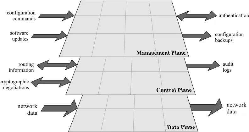
Conceptually, a router operates on three distinct domains or planes. The
management plane handles administration, configuration, and generally the persistent state of the router. The control plane covers monitoring, route table updates, and generally the dynamic operation of the router. The data or forwarding plane handles the packets transiting the router among the networks it serves.
configuration commands
software
updates configurationbackups
authentication
routing information
audit logs
cryptographic negotiations
network data
[image:33.612.131.527.272.482.2]network data
Figure 3-1: Three-Plane Conceptual Model for a Router
To secure a router, we must consider the possible threats to each plane. Threats to the management and control planes mostly concern unauthorized access to the router, or interference with router operation. Threats to the data plane usually concern violations of network security for the networks that the router supports.
3.1.
Protecting the Router Itself
3.1.1.
Physical Security
components kept on hand. To help protect against some denial of service attacks, and to allow it to support the widest range of security services, the router should be configured with the maximum amount of memory possible.* Also, the router should be placed in a locked room accessible only to authorized personnel. Physical devices (e.g., PC cards, modems) used to connect to the router require storage protection.
3.1.2.
Operating System
The operating system for the router is a crucial component. Decide what features the network needs, and use the feature list to select the version of the operating system. However, the very latest version of any operating system tends not to be the most reliable due to its limited exposure in a wide range of network environments. One should use the latest stable release of the operating system that meets the feature requirements. Section 3.3.2 discusses the management of updates to the operating system, and Sections 4 and 8 include information on Cisco’s IOS operating system.
3.1.3.
Configuration Hardening
A router is similar to many computers in that it has many services enabled by default. Many of these services are unnecessary and may be used by an attacker for
information gathering or for exploitation. Unnecessary services should be disabled in the router configuration. Section 3.3.2 discusses management of updates to the router configuration.
Router Security Principles and Goals
3.2.
Protecting the Network with the Router
3.2.1.
Roles in Network Operations and Security
Routers perform many different jobs in modern networks, but for this discussion we will examine three fundamental ways in which routers are employed.
Interior Routers
An interior router forwards traffic between two or more local networks within an organization or enterprise. The networks connected by an interior router often share the same security policy, and the level of trust between them is usually high. If an enterprise has many interior routers, they will usually employ an Interior Gateway Protocol to manage routes. Interior routers may impose some restrictions on the traffic they forward between networks.
Most of the directions in this guide are useful for interior routers.
Router
Internal LAN 3 Internal
LAN 1
Internal LAN 2
Figure 3-2: An Interior Router Connects an Organization’s Internal Networks
Backbone Routers
A backbone or exterior router is one that forwards traffic between different
enterprises (sometimes called different ‘autonomous systems’). The traffic between the different networks that make up the Internet is directed by backbone routers.
The level of trust between the networks connected by a backbone router is usually very low. Typically, backbone routers are designed and configured to forward traffic as quickly as possible, without imposing any restrictions on it. The primary security goals for a backbone router are to ensure that the management and operation of the router are conducted only by authorized parties, and to protect the integrity of the routing information it uses to forward traffic. Backbone routers typically employ Exterior Gateway Protocols to manage routes.
Router
Router
Router
Router
Figure 3-3: Backbone Routers Connect Many Networks
Border Routers
A border router forwards traffic between an enterprise and exterior networks. The key aspect of a border router is that it forms part of the boundary between the trusted internal networks of an enterprise, and untrusted external networks (e.g. the Internet). It can help to secure the perimeter of an enterprise network by enforcing restrictions on the traffic that it controls. A border router may employ routing protocols, or it may depend entirely on static routes.
Internet
Router
Internal Networks
Figure 3-4: A Border Router Connects Internal Networks to an External Network
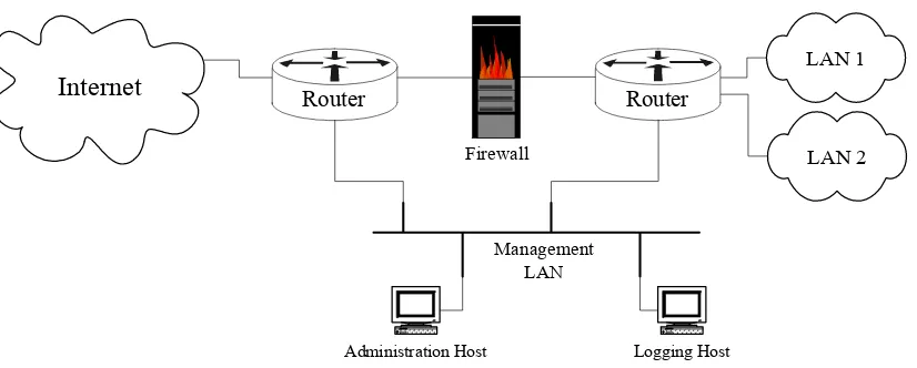
Typically, a border router is not the only component at the boundary; many enterprises also employ a firewall to enforce fine-grained security policy.
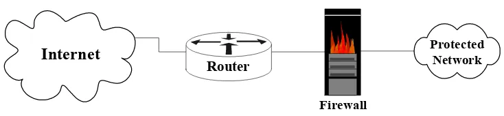
In the Figure 3-5, the border router acts as the first line of defense and is known as a screening router. It contains a static route that passes all connections intended for the protected network to the firewall. The firewall provides additional access control over connections and network traffic. The firewall may also perform user
Router Security Principles and Goals
Internet
Router
Protected Network
Firewall
Figure 3-5: A Simple One-Router Firewall Configuration for a Network Boundary
Another approach is to position one router at the connection between the external networks, and then another router between the firewall and the trusted internal networks. This configuration offers two points at which policy can be enforced. It also offers an intermediate area, often called the de-militarized zone (DMZ) between the two routers. The DMZ is often used for servers that must be accessible from the Internet or other external network.
Internet
RouterInternal Network
Firewall
Router
Premises or Gateway router
[image:37.612.152.519.92.177.2]Internal or Local net router
Figure 3-6: A Two-Router Firewall Configuration for a Network Boundary
All of the directions in this guide are suitable for border routers.
3.2.2.
Packet Filters for TCP/IP
A packet filter for TCP/IP services provides control of the data transfer between networks based on addresses and protocols. Routers can apply filters in different ways. Some routers have filters that apply to network services in both inbound and outbound directions, while others have filters that apply only in one direction. (Many services are bi-directional. For example, a user on System A telnets to System B, and System B sends some type of response back to System A. So, some routers need two filters to handle bi-directional services.) Most routers can filter on one or more of the following: source IP address, source port, destination IP address, destination port, and protocol type. Some routers can even filter on any bit or any pattern of bits in the IP header. However, routers typically do not have the capability to filter on the content of services (e.g. FTP file name).
from the internal or protected network (right to left) must bear a source address within a particular range. This is sometimes called egress filtering. Similarly, the router should enforce the constraint that packets arriving from the Internet must bear a source address outside the range valid for the protected network. This is a form of ingress filtering.
Two key characteristics of TCP/IP packet filters are length and ordering. A filter consists of one or more rules, with each rule either accepting or denying a certain set of packets. The number of rules in a filter determines its length. Generally, as the length grows the filter becomes more complex and more difficult to troubleshoot. The order of the rules in a packet filter is critical. When the router analyzes a packet against a filter the packet is effectively compared to each filter rule in sequential order. If a match is found then the packet is either permitted or denied and the rest of the filter is ignored. If no match is found then the packet is denied due to the implicit deny rule at the end of the filter. You must carefully create filter rules in the proper order so that all packets are treated according to the intended security policy. One method of ordering involves placing those rules that will handle the bulk of the traffic as close to the beginning of the filter as possible. Consequently, the length and ordering of a packet filter rule set can affect the router’s performance. (Note: This discussion is applicable to the packet filtering facilities of Cisco routers, most other kinds of routers, and most packet filtering firewalls. Cisco filtering is discussed in detail in Section 4.3. If you have a router made by a company other than Cisco Systems, consult its documentation for details).
Applying Packet Filters: Permit Only Required Protocols and Services
Carefully consider what network services will be allowed through the router
(outbound and inbound) and to the router. If possible, use the following guideline for creating filters: those services that are not explicitly permitted are prohibited. This guideline is especially important for border routers. Make a list of the services and protocols that must cross the router, and those that the router itself needs for its operation. Create a set of filtering rules that permit the traffic identified on the list, and prohibits all other traffic.
In cases where only certain hosts or networks need access to particular services, add a filtering rule that permits that service but only for the specific host addresses or address ranges. For example, the network firewall host might be the only address authorized to initiate web connections (TCP port 80) through the router.
Applying Packet Filters: Reject Risky Protocols and Services
Router Security Principles and Goals
[image:39.612.211.500.141.630.2]support them, the protocols listed in Table 3-1 should not be allowed across the router in either direction.
Table 3-1: Services to Block Completely at a Border Router
Port (Transport) Service
1 (TCP & UDP) tcpmux
7 (TCP & UDP) echo
9 (TCP & UDP) discard
11 (TCP) systat
13 (TCP & UDP) daytime
15 (TCP) netstat
19 (TCP & UDP) chargen
37 (TCP & UDP) time
43 (TCP) whois
67 (UDP) bootp
69 (UDP) tftp
95 (TCP & UDP) supdup
111 (TCP & UDP) sunrpc
135 (TCP & UDP) loc-srv 137 (TCP & UDP) netbios-ns 138 (TCP & UDP) netbios-dgm 139 (TCP & UDP) netbios-ssn
177 (UDP) xdmcp
445 (TCP) netbios (ds)
512 (TCP) rexec
515 (TCP) lpr
517 (UDP) talk
518 (UDP) ntalk
540 (TCP) uucp
1434 (UDP) Microsoft SQL Server
1900, 5000 (TCP & UDP) Microsoft UPnP SSDP
2049 (UDP) NFS
6000 - 6063 (TCP) X Window System
6667 (TCP) IRC
12345-6 (TCP) NetBus
31337 (TCP & UDP) Back Orifice
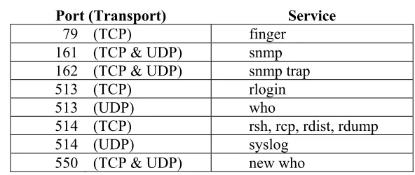
Table 3-2: Some Services to Block at the Router from External Clients
Port (Transport) Service
79 (TCP) finger
161 (TCP & UDP) snmp
162 (TCP & UDP) snmp trap
513 (TCP) rlogin
513 (UDP) who
514 (TCP) rsh, rcp, rdist, rdump
514 (UDP) syslog
550 (TCP & UDP) new who
Standard Ports and Protocols
Some organizations maintain a list of standard ports and protocols that should be allowed or supported on their networks. Various organization in the US DOD maintain such lists, and the Defense Information System Agency (DISA) is attempting to manage the creation of a standard list for the entire DOD.
For networks that are subject to such lists, it is best to take the first approach, allowing only those ports and protocols mandated by the standard list, and rejecting all others.
Address Filtering
Router filters should also be used to protect against IP address spoofing, especially on border routers. In most cases filtering rules should apply both ingress and egress filtering, including blocking reserved addresses. The principles to apply on border routers are listed below.
• Reject all traffic from the internal networks that bears a source IP address which does not belong to the internal networks. (Legitimate traffic generated by sources on the internal networks will always bear a source address within the range or ranges assigned to the internal networks; any other traffic is attempting to claim a bogus source address, and is almost certainly erroneous or malicious in nature.)
• Reject all traffic from the external networks that bears a source address belonging to the internal networks. (Assuming that addresses are assigned correctly, traffic sent from the external networks should always bear a source address from some range other than those assigned to the internal networks. Traffic bearing such spoofed addresses is often part of an attack, and should be dropped by a border router.)
• Reject all traffic with a source or destination address belonging to any reserved, unroutable, or illegal address range.
Router Security Principles and Goals
3.2.3.
Mitigating Denial of Service Attacks
Loss of service or severely degraded network performance can result from a variety of causes. Denial of Service (DoS) refers to willful attempts to cause such
disruptions. Though DoS attacks can be viewed as tolerable annoyances, they can have serious consequences if they occur during a time of crisis. There is no complete solution to the DoS problem; as long as the resources of a network are limited and openly available they will be vulnerable to attack. There are measures that network administrators can take to protect networks from DoS attacks and lessen their effects. These measures require some cooperative effort between those who administer hosts, network devices, and provider access. To be effective, these measures must be planned and in place before an attack occurs.
At the enterprise level there are three primary strategies for combatting DoS attacks, described in detail below.
1. Prevent malicious traffic from entering the common network from the enterprise network.
2. Configure and deploy local protective measures, at both border and interior routers.
3. Coordinate protective measures against distributed DoS attacks with network access providers and/or backbone administrators.
First, it is important for every network administrator to help reduce the number of DoS attack launch platforms. Do not let your network be the origin point for a DoS attack; keep hosts secure and eliminate compromised hosts from the network immediately. There are several mechanisms available on routers to thwart certain kinds of DoS attacks. Many of these attacks require use of invalid or spoofed source addresses. For example, invalid addresses are used in SYN flood attacks to ensure that the TCP handshake on the target host times out waiting for a response (see Section 6.3.2). There are several ways to filter out these improperly-addressed packets. Access control lists are a general filtering facility available on all routers (see Section 4.3). Black hole routing can also be useful, and works on all routers (see Section 4.4.6). Most Cisco routers support a facility called Unicast Reverse-Path Forwarding Verification that uses the route table to detect and drop improperly-addressed packets (see Section 4.4.7). Where possible, you should log occurences of bad packets, logging these violations can help identify compromised hosts that need to be removed from your network. Of course, detection will depend on reviewing the router logs on a regular basis.
TCP Intercept (see Section 4.3.3). In some cases, router traffic rate control or quality of service facilities can be used to protect critical services from the full effects of DoS attacks (see Section 4.3.6). Router facilities may also be supplemented by commercial anti-DoS products that provide finer-grained filtering and attack detection.
A border router cannot control the type or overall volume of traffic that is sent to it. DoS mitigation necessarily requires cooperative action “upstream,” i.e. from the access provider, (possibly from) the transport provider, the source point access provider, or even from the administrators of the attacking hosts. For example, as the packets of an ICMP flood converge at the uplink, legitimate traffic is crowded out by bogus traffic and packets are lost to traffic flow control. Connections and data transfers are starved and eventually time out or hang because they are unable to resynchronize. If your access provider performs statistical monitoring of traffic, they can take steps to block and trace back bad traffic as the attack ramps up. If no such quality of service monitoring exists, then the network being attacked will need to actively request its access provider filter out offending traffic.