UNIVERSITI TEKNIKAL MALAYSIA MELAKA
DESIGN AND DEVELOPMENT OF SHIELD FOR FIRE
RESISTANCE PURPOSE
This report is submitted in accordance with the requirement of the Universiti Teknikal Malaysia Melaka (UTeM) for the Bachelor Degree of Engineering Technology Bachelor
of Mechanical Engineering Technology (Maintenance Technology) with Honours.
by
PETER YEW KWONG YONG B071410204
940125-13-5815
DECLARATION
I hereby, declared this report entitled “Design and Improvement on a Fire Resistance Shield” is the results of my own research except as cited in references.
Signature : ………
Author’s Name : ………
APPROVAL
This report is submitted to the Faculty of Engineering Technology of UTeM as a partial fulfillment of the requirements for the degree of Bachelor of Mechanical Engineering Technology (Maintenance Technology) with Honours. The member of the supervisory is as follow:
i
ABSTRAK
Perisai telah digunakan sebagai alat pertahanan untuk infantri dan kesatria sejak
berabad-abad dahulu. Evolusi besar perisai terus berlaku dan ini membawa kepada
pembangunan progresif dan peningkatan reka bentuk perisai, contohnya perisai yang
banyak digunakan oleh anggota penguatkuasaan undang-undang hari ini. Walaupun
begitu, perisai untuk tujuan penyelamatan api masih belum direka. Kesesuaian interaksi
antara perisai dengan penggune juga menjadi suatu persoalan. Oleh itu, objektif projek
ini adalah untuk mencadangkan reka bentuk konseptual perisai, dengan pertimbangan
faktor ergonomik perisai. Metodologi yang digunakan adalah kaji selidik terhadap ahli
bomba untuk menentukan keperluan terhadap reka bentuk perisai, House of Quality (HoQ)
dalam menilai keperluan ahli bomba, carta morfologi dalam menentukan konsep, kaedah
pemilihan Pugh untuk pemilihan rekan bentuk yang paling sesuai, analisis RULA dalam
mengukur ergonomik, and akhirnya Finite Element Analysis (FEA) dalam
mensimulasikan kesan perisai bawah tekanan haba dan beban. Perisai berbentuk scutum
telah dipilih sebagai reka bentuk konseptual, dengan aloi aluminium 6061-T6 sebagai
bahan teras perisai, dan dibalut oleh serat karbon jenis modulus elastik (HT). Reka bentuk
perisai telah mencapai skor akhir 3 dalam analisis RULA untuk kedudukan bediri dan
melutut. Skor ini menunjukkan reka bentuk perisai mempunyai risiko gangguan
muskuloskeletal (MSD) yang rendah. Selain itu, keputusan FEA telah membuktikan sifat
mekanik kedua-dua bahan yang digunakan dalam reka bentuk perisai adalah selaras
ii
ABSTRACT
iii
DEDICATION
To my respected supervisor, my beloved family,
iv
ACKNOWLEDGEMENT
First and foremost, praises and thanks to God, the Almighty, for His showers of blessings to complete this final year project successfully.
I would like to express my deep and sincere gratitude to my project supervisor, Mr. Mohamed Saiful Firdaus Bin Hussin, lecturer of Engineering Technology Faculty from University Technical Malaysia Malacca (UTeM). The door to Mr. Saiful Firdaus was always open whenever I ran into a trouble spot or had a question about my project or writing. His sustained enthusiasm, patience and consistent guidance steered me in the right direction whenever he thought I needed it, and now, I can have my final year project completed successfully.
I am extremely grateful to my parents for their love, caring, prayers and sacrifices for educating and nurturing me for my future. Their wise counsel and sympathetic ear have always comforted me. I have never short of any necessities all the way as they do know, and prepare what I may need.
v
TABLE OF CONTENT
Abstrak i
Abstract ii
Dedication iii
Acknowledgement iv
Table of Content v
List of Tables ix
List of Figures x
List of Abbreviations, Symbols and Nomenclatures xii
CHAPTER 1: INTRODUCTION 1
1.1 Background 1 1.2 Problem statement 3 1.3 Objectives 4 1.4 Scope of research 4 CHAPTER 2: LITERATURE REVIEW 5
2.1 Types of Shield 5 2.1.1 Capture Shield 5 2.1.2 Ballistic Shield 7 2.1.3 Riot Shield 9
2.1.4 Buckler for Melee Fighting 11 2.2 Advantages and Disadvantages of Shield Utilization 12 2.2.1 Advantages of Shield Utilization 12 2.2.2 Disadvantages of Shield Utilization 12 2.3 Engineering Design 13
2.3.1 Brainstorming and Customer Survey 13
vi
2.3.3 Product Design Specification (PDS) 15
2.3.4 Morphological Chart 16
2.3.5 Conceptual Design 19
2.4 Ergonomics Analysis 20
2.4.1 Rapid Entire Body Assessment (REBA) 20 2.4.2 Rapid Upper Limb Assessment (RULA) 21 2.4.3 Digital Human Models (DHMs) 23
2.5 Classification of Materials 24
2.5.1 Metals 25
2.5.2 Polymers 26
2.5.3 Ceramics 27
2.5.4 Composites 27
2.6 Material Selection 28
2.6.1 Polycarbonate 28
2.6.2 Carbon Fiber 29
2.6.3 Aramid Fiber 30
2.6.4 Silicon Carbide 31
2.6.5 Silicon Nitride 31
2.6.6 Tungsten Carbide 32
2.6.7 High Carbon Steel 33
2.6.8 Aluminium Alloy 34
2.7 Ashby Charts Method 35
2.8 Pugh Selection Method 36
CHAPTER 3: METHODOLOGY 38
3.1 Introduction 38
3.2 Flow Chart 39
3.3 Customer Survey 41
3.4 House of Quality (HoQ) 41
3.5 Product Design Specification (PDS) 43
vii
3.7 Conceptual Design 44
3.8 Material Selection 45
3.8.1 Carbon Fiber 45
3.8.2 Aluminium Alloy 45
3.8.3 Silicon Carbide 46
3.9 Ergonomics Analysis 46
3.10 Pugh Selection Method 46
CHAPTER 4: RESULT & DISCUSSION 48
4.1 Survey Analysis 48
4.2 House of Quality (HoQ) 56
4.3 Morphological Chart 58
4.4 Pugh Selection Method 59
4.5 Conceptual Design 61
4.6 Parametric Design 64
4.6.1 SolidWorks Drawing 65
4.7 Ergonomics Analysis 67
4.8 Finite Element Analysis (FEA) 69
4.8.1 Load Exertion on Aluminium Alloy 70
4.8.2 Thermal Exertion on Aluminium Alloy 73
4.8.3 Thermal Exertion on Carbon Fiber 76
CHAPTER 5: CONCLUSION & RECOMMENDATION 79
5.1 Introduction 79
5.2 Conclusion 79
5.3 Recommendation for Future Work 80
viii APPENDICES
ix
LIST OF TABLES
2.1 Comparison between Material Properties 19
3.1 Morphological Chart 49
3.2 Pugh Decision Matrix
4.1 Morphological Chart of Shield 57
x
LIST OF FIGURES
2.1 Capture Shield 20
2.2 Ballistic Shield (Front View) 20
2.3 Ballistic Shield (Back View) 21
2.4 Riot Shield 21
2.5 Buckler for Melee Fighting 22
2.6 Four Houses of QFD Process 22
2.7 Example of House of Quality (HoQ) Template 22
2.8 Function Structure for a Disposable Syringe 22
2.9 Morphological Chart for Disposable Syringe 22
2.10 Commonly Used Engineering Materials for Structural Applications 22 2.11 Ashby Material Selection Chart: Elastic Modulus versus Density 22
3.1 Process Flow Chart 32
3.2 House of Quality (HoQ) of Firefighting Shield 35
4.1 Age of Respondent 45
4.2 Height of Respondent 45
4.3 Number of Fire Cases Experienced 45
4.4 Best Position of Put Off Fire 46
4.5 Movement Obligation by Using Shield 46
4.6 Best Shape Design for Shield 47
4.7 Surface Design of Shield 47
4.8 Best Dimension of Shield 48
4.9 Added Feature on Shield 49
4.10 Suitable Material for Shield Fabrication 49
4.11 Expected Melting Point of Shield 50
xi
4.13 Expected Weight of Shield 51
4.14 Need of Stand for Storage of Shield 51
4.15 Estimated Price for Production of Shield 52
4.16 House of Quality (HoQ) 53
4.17 Fire Resistance Shield (Front View) 59
4.18 Fire Resistance Shield (Back View) 60
4.19 Shield Stand 60
4.20 Parametric Design of Shield 61
4.21 Isometric Front and Back Views of Shield 62
4.22 Front and Back Views of Shield 63
4.23 Right and Left Views of Shield 63
4.24 Manikin in Standing Position 64
4.25 Manikin in Kneeing Position 64
4.26 Displacement of Aluminium 6061-T6 Shield under Load Exertion 65 4.27 Graph of Load versus Displacement for Aluminium 6061-T6 66 4.28 Von Mises Stress of Aluminium 6061-T6 Shield under Load Exertion 67 4.29 Graph of Load versus von Mises Stress for Aluminium 6061-T6 68 4.30 Displacement of Aluminium 6061-T6 Shield under Temperature 69 4.31 Graph of Temperature versus Displacement for Aluminium 6061-T6 70 4.32 Von Mises Stress of Aluminium 6061-T6 Shield under Temperature 71 4.33 Graph of Temperature versus Von Mises Stress for Aluminium 6061-T6 72 4.34 Displacement of Carbon Fiber Coated Shield under Temperature 73 4.35 Graph of Temperature versus Displacement for Carbon Fiber 73 4.36 Von Mises Stress of Carbon Fiber Coated Shield under Temperature 73 4.37 Graph of Temperature versus Von Mises Stress for Carbon Fiber 73
xii
LIST OF ABBREVIATIONS, SYMBOLS AND
NOMENCLATURE
FEA - Finite Element Analysis GPa - Giga Pascal
HoQ - House of Quality M-Chart - Morphology Chart
mm - Milimiter
MPa - Mega Pascal
ms-1 - Meter per second
oC - Degree Celcius
1
CHAPTER 1
INTRODUCTION
1.1 Background
Ever since the ancient times, mankind have always attempted to protect themselves from antagonist. The caveman’s clothing made of thick animal skin was found to be the first body armour documented in history, followed by the invention of wooden and metal shields to protect one’s body (Stanley, 2004). Body armour is usually worn for an extended period of time and over long distances during military, police and law enforcement activities (Ricciardi et al., 2008).
Armours have been developed to accommodate the increasing and ever-changing methods of inflicting harm. A study done by Howard et al., (2013) showed some of the earliest armours worn by the soldiers in Japan during the fourth century includes iron helmets and cuirasses, followed by the lamellar armour which found to be used by the fifth century. Cuirasses are made of iron plates strapped together with metal thongs, whereas lamellar armours are configured by stitching metal pieces or rectangular leather together in rows. These designs of armours can greatly reduce the impact of sword blows and arrows, hence provide protection to the part of body where the armour offered protection. However, soldiers during these early centuries were not equipped with a full and complete set of armours. They relied on a large piece of shield for protection of all parts of their body (Ffoulkes, 1967).
2 for a better protection had kept the developments went drastically with both the Western and Eastern civilisations having immense clash over the 11th to 13th century. Shields were usually reliable defence for infantrymen and knights before plate armour became a commonplace form of guard. Various types of material, either metal or non-metal like wood, had been used in crafting shields. Soldiers who can afford only low price shields used to combine thick sheets of wood with paste and tanned leather to create a durable aegis. However, it differed from iron-made-shields which simply dent under blows from weapons, wood-crafted-shields tend to crack and fall apart if they were suffered from heavy impact (Howard et al., 2013). Investigation on suitable material in the making of shield has grown progressively, while more and more lightweight, yet high strength material are made possible for shields of different purposes, such as riot shields, ballistic shields and military shields. For instance, soft ballistic vests which are made of synthetic fibres: Kevlar, Spectra, or Zyloflex, have been available to law enforcement officers since 1973.
Over the time, development of shields focused not only on its crafting material or composition, but on the ergonomic factor as well. For instance, as described by Howard et.al (2013), the straps located behind the blocking part of shield were reshaped for better control over blocking. A handle or strap would be grasped by hand, and the secondary strap would fit over arm. This enables soldiers to put the power of their weight behind blocks and attacks. This is supported by Czarnecki & Janowitz (2003) that modern body armour is more comfortable and flexible than ever.
3
1.2 Problem Statement
At present, there are a lot of shields designed for law enforcement, but a shield for fire fighting purpose is yet to be designed and made. In fact, it is undeniable that the use of fire fighting shield will greatly reduce the risk of hazards faced by fire-fighters during fire rescue activities. A study done by Fahy et al. (2015) indicated a total of 64 fire-fighters was reported dead while on-duty in the U.S. in 2014. The two double-fatality fires, both occurred in apartment buildings are the largest multiple-death incidents occurred in U.S. in 2014. In one of those fires, there were two victims who caught in a rapid fire event and suffered from fatal burns while they were operating a hoseline. In another fire, two victims were trapped in the basement were primarily identified to suffer from fatality burns, and died of smoke inhalation. One additional fire which is also occurred in an apartment building had killed a fire-fighter who was trapped by rapid progress of fire while searching for dwellers in the high-rise building. Thus, a shield for fire fighting purpose literally provides the fire-fighters with a large coverage of protection against the failing high-heat structures or objects.
According to Cheuvront et al. (2008), a research done by military has demonstrated a significant decrease in performance and a greater physiological demands when individuals are required to carry excess weight for an extended period of time. The law enforcement equipped with excessive protection will have limited movement ability and they are most likely to struggle with the more important movements for survival purpose. They are decreased not only in tactical mobility, but in their velocity and acceleration as well (Lewinski et al., 2015). Therefore, lightweight raw material is sought in designing the fire fighting shield to ensure fire fighters retain their flexibility in their movements.
4 parts of human exercises (Cañas & Velichkovsky, 1997). It is in particular responsible for the design and evaluation of shield to make it compatible with the working environment, needs and limitations of fire fighters. This is supported by Czarnecki & Janowitz (2003) in which an equipment has to be evaluated for its efficacy, reliability, risks for acute or chronic injuries, and associated risk for litigation.
1.3 Objectives
Based on the problem statements discussed above, the objectives of this study are:
1. To conduct a survey on the ergonomic factors in designing a fire resistance shield.
2. To design the concept of lightweight fire resistance shield according to customer requirements.
3. To analyse human factors in the handling of shield, and to perform Finite Element Analysis (FEA) on the shield.
4. To fabricate a lightweight shield prototype with fire resistance properties.
1.4 Scope of Research
The scopes of this research work are established based on the objectives mentioned:
1. The survey is done by interviewing at least twenty fire department officers stated in Malaysia.
2. The customer requirements are defined and translated into engineering characteristics for further design process development of fire resistance shield. 3. The suitability and comfort between manikin and shield is analysed by using RULA analysis, and the Finite Element Analysis is performed by using solidThinking Inspire software.
5
CHAPTER 2
LITERATURE REVIEW
2.1 Types of Shield
Shields, as in any type of armour or weapon, developed and changed over centuries. They are also changed in shape and size, as well as the addition of special features to provide convenience and extra functions to the shield.
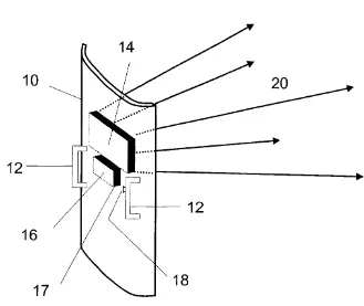
[image:20.595.192.521.385.662.2]2.1.1 Capture Shield
Figure 2.1: Capture Shield (Tocci et al., 2002)
6 or Lexan®. The shield (10) is equipped with sturdy handles (12). A light housing (14) is mounted on the centre of shield (10) and it is electrically connected to a power supply housing (16), with a main power switch (17). On one of the handles (12), a three position action switch (18) is mounted. When it is pressed, the LED array turns on with continuous light output (Tocci et al., 2002).
During the task of seizing an uncooperative, and perhaps armed criminal, officers can use a “capture” shield to pin the subject down. The capture shield which its edges curved outward allows the officers to entrap the struggling inmate against a wall or floor. The effectiveness of this capture shield to subdue an inmate is further enhanced through the high-intensity, broad-area light source to deter and disorient the inmate. This present invention uses a plurality of high-brightness light source arrays to provide a large area of high luminous intensity for visual response. The sudden burst of light source arrays will surprise the inmate and he or she may close his or her eyes, or to look away. This allows the officer to seize the chance to effectively tackle down the subject (Tocci et al., 2002).
7
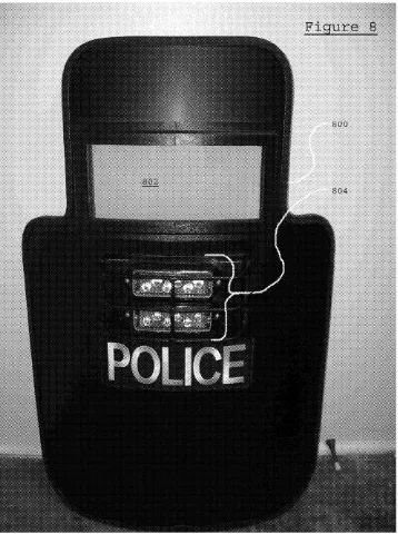
[image:22.595.248.427.118.358.2]2.1.2 Ballistic Shield
[image:22.595.246.429.411.660.2]Figure 2.2: Ballistic Shield (Front View) (Dovner, 2010)
Figure 2.3: Ballistic Shield (Back View) (Dovner, 2010)
8 which a viewport, measure about 5.5 × 10 inches in size and made of transparent ballistic material such as polycarbonate is allocated to provide law enforcement personnel with visibility therethrough. The upper part has a width sufficiently wide to provide coverage to the head of user. The lower part of the shield is configured to protect the user body from ballistic harm. Its width is at least a torso of the user, which is simply greater than the upper part. In order to enable the shield to stand in an upright position by itself, this present invention of ballistic shield consists at least one connection position at the lower part of shield where foot can attach thereto.
The upper part of ballistic shield is configured to be centrally aligned in relation to the lower part. This is to facilitate ambidextrous use of shield by law enforcement personnel. This configuration permits user to deploy firearm and shield with either of their hands. The flanges designed at each side of intersection between the upper and lower parts provide support for firearm. The flange is configured at both sides of the shield so that either a left-handed or a right-handed user can utilize the shield well. As seen in these figure 2.2 and 2.3, the shield may also include battery-operated spotlights, handle, strap and padding to ease the user grip and manipulate the shield (Dovner, 2010).
9
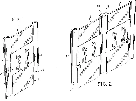
[image:24.595.239.477.127.304.2]2.1.3 Riot Shield
Figure 2.4: Riot Shield (Bauer, 1989)
Figure 2.4 illustrates the present invention of riot shield. A riot shield is essentially made of polycarbonate sheet with two handles secured at its back which allow the law enforcement personnel to carry it. Since the riot shield is made of polycarbonate material, it is lightweight, yet tough as well as shock and fire resistant. Moreover, polycarbonate material can be in transparent, thus allows officer to see through it the situation faced. These features have made it perfectly meet the requirements as a riot shield.