1
UNIVERSITI TEKNIKAL MALAYSIA MELAKA
DEVELOPMENT OF ANTI-THEFT CAR SECURITY USING
SMS SYSTEM
This report submitted in accordance with requirement of the Universiti Teknikal Malaysia Melaka (UTeM) for the Bachelor Degree of Engineering Technology
(Robotic & Industrial Automation) (Hons.)
by
SHAZATUL ATHIRAH BINTI MOHD SALLEH B071310925
921110-10-5652
ii
UNIVERSITI TEKNIKAL MALAYSIA MELAKA
BORANG PENGESAHAN STATUS LAPORAN PROJEK SARJANA MUDA
TAJUK: DEVELOPMENT OF ANTI-THEFT CAR SECURITY USING SMS SYSTEM
SESI PENGAJIAN: 2016/17 Semester 2
Saya SHAZATUL ATHIRAH BINTI MOHD SALLEH
mengaku membenarkan Laporan PSM ini disimpan di Perpustakaan Universiti Teknikal Malaysia Melaka (UTeM) dengan syarat-syarat kegunaan seperti berikut:
1. Laporan PSM adalah hak milik Universiti Teknikal Malaysia Melaka dan penulis. 2. Perpustakaan Universiti Teknikal Malaysia Melaka dibenarkan membuat salinan untuk
tujuan pengajian sahaja dengan izin penulis.
3. Perpustakaan dibenarkan membuat salinan laporan PSM ini sebagai bahan pertukaran antara institusi pengajian tinggi.
4. **Sila tandakan ( )
SULIT
TERHAD
TIDAK TERHAD
(Mengandungi maklumat yang berdarjah keselamatan atau kepentingan Malaysia sebagaimana yang termaktub dalam AKTA RAHSIA RASMI 1972)
(Mengandungi maklumat TERHAD yang telah ditentukan oleh organisasi/badan di mana penyelidikan dijalankan)
Alamat Tetap:
LOT 2982 KG BATU 6
JALAN KEBUN
40460 SHAH ALAM SELANGOR
Tarikh: 9 DECEMBER 2016
Disahkan oleh:
Cop Rasmi:
iii
DECLARATION
I hereby, declared this report entitled “DEVELOPMENT OF ANTI-THEFT CAR SECURITY USING SMS SYSTEM” is the results of my own research except as
cited in references
Signature : ……….
Author’s Name : SHAZATUL ATHIRAH BINTI MOHD SALLEH
iv
APPROVAL
This report is submitted to the Faculty of Engineering Technology of UTeM as a partial fulfillment of the requirements for the degree of Bachelor of Engineering Technology (Industrial Automation & Robotics) (Hons.). The members of the supervisory committee are as follow:
………
(Principal Supervisor)
………
v
ABSTRAK
vi
ABSTRACT
vii
DEDICATION
The dediction of this work was just conceivable because of the few individuals' coordinated effort, to which craving to express my thankfulness. To my folks, thank you for your unequivocal backing with my studies. I am are respected to have both of you as my folks. Much obliged you for allowing me to demonstrate and enhance myself through every one of my strolls of life.
viii
ACKNOWLEDGEMENT
Alhamdulillah, praise to Allah S.W.T for His Mercy that showered, I ready to finish this task. Peace upon to our Prophet Muhammad S.A.W as the best case to human sorts. In finishing this dissertation, as a fractional satisfaction of the prerequisite Bachelor of Electrical Engineering Technology (Industrial Automation and Robotics) with Honors. I am obliged to numerous people for their backings and supportive gestures. Their commitments are very esteemed and acknowledged.
Most profound appreciation supervisor, Puan Intan Mastura Binti Saadon and Co-Supervisor, Puan Rosziana Binti Hashim for tolerance and direction to make this dissertation simpler for me to complete it on time. All the advices, suggestions, and remarks will dependably be recalled, with the end goal of this paper as well as in our future study. Not to overlook my folks for their unified love and bolster that has endured.
To wrap things up, I might want to thank both my panel, Pn Rozilawati Mohd Nor and Encik Ahmad Muzaffar Abdul Kadir. Additionally, thank to every one of my partners who strolled the same way in accomplishing our Bachelor, all lecturer in Universiti Teknikal Malaysia Melaka (UTeM) for their time and inestimable encounters shared. Only Allah S.W.T. is the best in compensating every one of these backings and makes a difference.
ix
TABLE OF CONTENT
DECLARATION ... iii
APPROVAL ... iv
ABSTRAK ... v
ABSTRACT ... vi
DEDICATION ... vii
ACKNOWLEDGEMENT ... viii
TABLE OF CONTENT ... ix
LIST OF TABLE ... xi
LIST OF FIGURE ... xii
LIST ABBREVIATIONS AND SYMBOLS ... xiv
CHAPTER 1 ... 1
INTRODUCTION ... 6
1.1 Problem Statement ... 2
1.2 Objective of Project ... 2
1.3 Scope of Project ... 2
1.4 Thesis Structure ... 3
1.5 Flow Chart ... 5
CHAPTER 2 ... 6
LITERATURE REVIEW ... 6
2.0 Introduction ... 6
2.1 Related Work ... 6
2.1.1 Microcontroller Based Anti-Theft Security System Using GSM Networks with Text Message as Feedback ... 6
2.1.2 An Intelligent Tracking System Based on GSM and GPS using Smartphones... 7
2.1.1 Design and Construction of A Remotely Controlled Vehicle Anti-Theft System via GSM Network ... 7
2.2 Global System for Mobile Communication (GSM) Modem ... 7
x
2.3 Mobile Phones ... 9
2.3.1 Short Messaging Service ... 10
2.3.1.1 Applications of Short Messaging Service…………...10
2.3.1.2 Operational Mode: Short Messaging Service Text and Short Messaging Service PDU…………...11
2.3.1 Short Messaging Service Protocols ... 13
2.4 AT Command ... 14
2.4.1 Types of AT Commands ... 17
2.4.2 Generally Syntax of Extended AT Commands ... 18
2.5 PIC Microcontroller... 60
2.5.1 PIC Microcontroller Pin Configurations ... 60
2.6 Software Specification ... 63
2.6.1 Proteus 8.0 Professional ... 63
2.5.2 MikroC MikroElekttronika C Compiler ... 63
2.5.2 PICkit 2 ... 63
CHAPTER 3 ... 25
METHODOLOGY ... 25
3.0 Introduction ... 25
3.1 Flow Chart ... 26
3.2 Project Flow Planning ... 28
3.2.1 Design the basic PIC Microcontroller with Basic Input / Output ... 28
3.2.2 Regulated Power Supply ... 29
3.2.3 Magnetic Switch... 30
3.2.4 LED and Buzzer as indicator ... 31
3.2.5 Liquid Crystal Display ... 33
3.2.6 Boot Loader ... 34
3.3 Hardware Implementation ... 35
3.3.1 Electromagnetic Lock ... 35
xi
CHAPTER 4 ... 38
RESULTS & DISCUSSIONS ... 38
4.0 Introduction ... 38
4.1 System Overview ... 38
4.2 Result Overall Project ... 39
4.2.1 Result from Project for Situation 1 ... 39
4.2.2 Result from Project for Situation 2 ... 40
4.2.3 Result from Project for Situation 1 ... 41
4.2.4 Result from ALRM RST ... 42
4.2.5 Result from ALRM LCK ... 43
4.3 Analysis Duration SMS ... 44
4.3.1 Duration SMS When Starting The System ... 44
4.3.2 Duration SMS For The Full System ... 46
4.3.3 Graph Analysis of Hardware ... 46
4.4 Discussion from Overall Result and Analysis ... 48
CHAPTER 5 ... 50
CONCLUSIONS & FUTURE WORK ... 50
5.0 Introduction ... 50
5.1 Conclusion ... 50
5.2 Advantage of System ... 51
5.3 Suggestion for Improvement ... 51
REFERENCES ... 52
xi
LIST OF TABLE
Table 2.1 Table 2.1: Show string receive by phone 14
Table 2.2 PDU Format 15
Table 2.3 Types of AT Command 17
Table 2.4 Common Syntax of Extended
AT Commands 18
Table 2.5 PIC 16F877A microcontroller pin description 20
Table 3.1 Specification of BEL-M5 Vibration Sensor 37
Table 4.1 The result for situation 1 40
Table 4.2 The result for situation 2 41
Table 4.3 The result for situation 3 42
Table 4.4 Time Taken From System Reboot To
System Online 44
Table 4.5 Time Taken Received SMS from System Online
To Owner Phone 45
xii
LIST OF FIGURE
Figure 2.1 Design of Global System for Mobile Communications
Network 8
Figure 2.2 PIC 16F877A 22
Figure 3.2 Overall drawing system of this project 28
Figure 3.3 Design of basic input / output 29
Figure 3.4 Simulation for Regulated Power Supply 30
Figure 3.5 Simulation for Magnetic Switch 30
Figure 3.6 Light Emitting Diode 31
Figure 3.7 Buzzer 32
Figure 3.8 Simulation for implement of car model 33
Figure 3.9 Basic simulation of LCD 16 x 2. 34
Figure 3.10 Schematic diagram for MAX 232 and RS232 35
Figure 3.10 Electromagnetic lock 36
Figure 3.11 BEL-M5 Vibration Sensor 37
Figure 4.1 The result before ALRM RST 43
Figure 4.2 Circuit for ALRM LCK 44
Figure 4.3 System Initialization 45
Figure 4.4 System Online 1 45
Figure 4.5 System Online 2 45
Figure 4.6 Notification 45
Figure 4.6: The graph of analysis between Distance
xiii
Figure 4.8 The graph of analysis between Distance
xiv
LIST ABBREVIATIONS AND SYMBOLS
GSM = Global System communication for mobile phone
GPRS = General Packet Radio Service
GMSK = Gaussian Minimum Shift Type
GPS = Global Positioning System
PDU = Protocol description unit
ISP = Internet Service Provider
IC = Integrated circuit
LED = Light emitting diodes
LCD = Liquid Crystal Display
PIC = Programmable Interface Controller
MAP = Mean Arterial Pressure
SS7 = Signaling System Number Seven
SMS = Short Messaging Service
ISIS = Intelligent Schematic Input System
UART = Universal Asynchronous Receiver/Transmitter
BDP = Bachelor Degree Project
GSM = Global System communication for mobile phone
GPRS = General Packet Radio Service
GMSK = Gaussian Minimum Shift Type
GPS = Global Positioning System
xv
ISP = Internet Service Provider
IC = Integrated circuit
LED = Light emitting diodes
LCD = Liquid Crystal Display
PIC = Programmable Interface Controller
PDU = Protocol description unit
RC = Radio Controlled
SMS = Short Messaging Service
1
CHAPTER 1
INTRODUCTION
In the period of globalization, crime rate is expanding step by step as it is entirely obvious from the way that robberies have turned into a matter of schedule. The auto burglary especially causes the proprietor to acquire gigantic misfortune as a part of the sum contributed on their auto. The security framework has been improved in all fields in the general public. Car security has conjointly earned a few expedient changes, however, the estimation of all security redesigns are so high and are not sensible for vehicle proprietors. In this manner, the need of great importance might be a higher hostile to robbery framework which will be upheld abuse numerous advancements.
This venture is planned to give the most straightforward security answer for the vehicles at a sensible cost. It gives another style to a hostile to robbery framework as a sensible answer for shield for autos from being taken and from intruders client by utilizing PIC. This venture joined the short messaging system as an enhancement for a more secure and simple car security system. The short messaging system is getting utilized among this venture since it incorporates a higher scope in each indoor and open air environment. Furthermore, short messaging system being the main innovation is widely used considering nations all over the world.
2
of a minute, the proprietor will cut off the alarm and shutdown the auto framework. It is normal that this venture can expand the auto security framework and might diminish the wrongdoing of auto taking.
1.1 Problem Statement
These days, the security framework inside the auto is not sufficient to determine the matter of auto taking. It doesn't have any electronic gadget framework snared thereto. The auto criminal exclusively simply takes a few seconds or minutes to deactivate the security framework that as of now being secured into the at auto by the manufacturers. Other than that, nobody can give careful consideration once the auto alert burst. Once the auto is stolen, it is becomes elusive to track the auto back. Besides that, one amongst the matter is the constraint of shift location for caution. Bolstered these reasons, an against burglary auto ready framework utilizing short messaging framework is anticipated to help the execution of this auto security framework.
1.2 Objective Of Project
The objectives of this project are:
1) To develop the prototype of anti-theft car security system which will find the prevalence of car theft.
2) To build an extra feature to the current security system that may warn the owner of the car by causing notification once there has been an intrusion into the car. Owner also can send the instruction to cut off / reset the car.
1.3 Scope Of Project
3
message to the system wherever it’ll send a notification to the owner. The scope of this project is split into 2:
a) Design a car alarm system which will detect whenever stealing happens or non-authorized people - Software implementation using PIC, Hardware implementation using 16F877A microcontroller, magnetic lock and vibration sensor.
b) Design a system that may send notification to owner when the car detect
the motion. – Using short message system (SMS) via Global System for Mobile Communication (GSM) modem.
1.4 Thesis Structure
This proposal consists of five chapters that may describe the various components of the project. Every chapter can justify every half in terms of software and hardware thereon chapter. The contents includes info of elements utilized in this project.
Chapter I: This chapter will justify the project in terms of objectives, statement
of the matter, scope and causes of issues that make this project.
Chapter II: This chapter describe the literature review of current problems and
reviewing previous terms of journal thesis. This chapter also will examine somewhat of the half utilized in the project.
Chapter III: This chapter specialize in the methodology utilized in the project.
This project consists of the two ways whereby can use software and hardware. Each divisions are delineate.
Chapter IV: This chapter will discuss result and analysis detailed on designing of
4 Chapter V: This chapter will discuss about discussion, issue, conclusion and
5 1.5 Flow chart
Start
Literature Review
Circuit Design
Software Implementation
& Simulation Write Program
for PIC
1
1
Software & Hardware Integration
End Hardware Development
Test & Troubleshooting
NO
NO
YES NO YES
6
CHAPTER 2
LITERATURE REVIEW
2.0 Introduction
This section judges an exact references and data from the previous tasks among ideas that are related to malfunction in automotive alarm. In addition, this chapter will elaborate explanation regarding the software and hardware throughout this project. This section justifies and discusses the literature reading that is said to the development of the anti-theft automotive alarm. This chapter reviews each part utilized within the system. The part concerning are PIC, electromagnetic lock, vibration sensor, GSM Modem and a few device and software application are explained.
2.1 Related Work
2.1.1 Microcontroller Based Anti-Theft Security System Using GSM Networks with Text Message as Feedback
7 2.1.2 An Intelligent Tracking System Based on GSM and GPS Using Smartphones
The security and theft interference area unit the most areas in current state of affairs. This is achieved by using GSM and GPS technology. By using this technology, it solely can’t track and monitor the vehicle in current position of the two wheeler. The position of this two wheeler acquired by GPS module that is interfaced to microcontroller and to the user of smartphone by using GSM Module. It addition, is implement this technique by using Atmel microcontroller. This vehicle chase system is consistent with Vigneshwaran.K, (2015).
2.1.3 Design and Construction of A Remotely Controlled Vehicle Anti-Theft System via GSM Network.
Consistent with analysis by Alli, Ijeh-Ogboi & Gbadamosi, (2015), this project remotely controlled via GSM network. This project is split into two scheme that is vehicle scheme and device access link. This technique is the same as the previous connected work however it was solely explored to trace down the precise location however not to demobilize the vehicle. It additionally sent a warning immediately to user’s phone and report the condition of the car to forestall the car from being taken by unauthorized person.
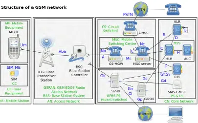
2.2 Global System for Mobile Communications (GSM) Modem
8
[image:24.595.120.526.231.483.2]is seen as a system of mobile phones of second generation ( 2G ) . GSM is an open normal that is presently developed by 3G. Overview of the Global System for Mobile Communication (2010) shows that GSM additionally supports SMS text messaging is additionally consistent with John. Scourias, University of Waterloo, (May 1995). Figure 2.1 shows the Design of Global System for Mobile Communications Network.
Figure 2.1: Design of Global System for Mobile Communications Network