Multi-port Power Conversion Systems for the More
Electric Aircraft
Chunyang Gu, He Zhang, Giampaolo Buticchi
Power Electronics, Machines and Control Research Group
University of Nottingham Ningbo China
Ningbo, China chunyang.gu@nottingham.edu.cn
Giacomo Sala, Alessandro Galassini, Savvas Papadopoulos, Michele Degano
Power Electronics, Machines and Control Research Group
University of Nottingham
Nottingham, United Kingdom
giacomo.salai@nottingham.ac.uk
Abstract—In the framework of the More Electric Aircraft (MEA), weight reduction and energy efficiency constitute the key figures. In addition to these requirements, the safety and the continuity of operation is of critical importance. These sets of desired feature are in disagreement, because the redundancy needed to guarantee the safety of operation implies necessarily in additional weight. Several concepts of the electrical power distribution systems have been proposed, in this manuscript, an approach based on the widespread use of multi-port power converters both for the DC/DC and for the DC/AC stages is proposed. These two technologies allows for a ring distribution of the electrical power whereas the galvanic isolation is still kept. Simulation and experimental results show the feasibility of the concept in common and fault operation conditions.
Keywords—more electric aircraft (MEA), multi-port active bridge (MAB), electrical power distribution system (EPDS), segmented driven starter/generators
I. INTRODUCTION
More electric aircraft (MEA) draw a lot of attention of power electronic expert as it is in the area of both smart power distribution, micro grid and also transportation electrification. In the field of power distribution and micro grid, the increasing energy demand challenged the aircraft power distribution systems with the critical requirement of safety and reliability [1]. A futuristic concept envisages the substitution of the oil distribution with electro-mechanical actuators or even fully electrical actuators, further increasing the electric power requirements. In the field of transportation electrification [2], the development of generation distribution and storage as well as advanced information communication have laid great foundation of next generation more electric aircraft (MEA).
In MEA framework, electrical generators are usually 3-phase AC systems, whereas most of the loads are DC loads, or AC loads with different magnitude/frequency requirement. Therefore, the so called Transformer-Rectifier Units (TRU) [3] are established in MEA for feeding different loads. The TRU realize galvanic isolation by transformers and convert AC to DC
by using rectifiers. Besides, AC, DC or hybrid buses are implemented in MEA for power distribution.
To improve the weight/volume consumption and efficiency as well as increase the safety and availability of the electrical power distribution system (EPDS), this paper proposes multi-port power conversion systems [4]-[5]. With this concept of multi-port power converters both for the DC/DC stages (i.e. multiple active bridge converter) and for the DC/AC stages (segmented inverters), a ring distribution of the electrical power whereas the galvanic isolation is established with more redundancy.
The paper is organized as follows, section II describes the possible electrical distribution system paradigms, section III describes the concept of multi-port power conversion systems, section IV and V presents the simulation and experimental results related to a fault in the AC side and section VI draws the conclusion.
II. EELETRICAL POWER DISTRIBUTION SYSTEM (EPDS)
There are several standards for the electrical distribution system of today’s aircraft, mainly referring to the MIL-STD-704. Considering the actual trends of electrification, a voltage increase (bipolar distribution) is also envisaged.
The possible voltage and frequency levels are:
• 28 V DC - low power loads/avionics on large aircraft and complete electrical system on small aircraft.
• 270 V DC (bipolar ±135V ) - military aircrafts and some subsystems on some larger aircrafts.
• 115 V AC at 400 Hz - larger loads on large civilian aircrafts.
• 115 V AC variable frequency from 360 Hz to 800 Hz.
• 540 V DC (bipolar ±270V ).
• 230 V AC at 400 Hz.
Different types of load are considered in MEA: fuel and oil pumps [6] and micro turbines are AC loads, actuators, battery
storages and avionics are DC loads. The mixture of both AC and DC loads requires a complicated structure of electrical power distribution systems (EPDS) where the main generators and an auxiliary power unit (APU) supply the main bus. Different architectures for the hybrid EPDS have been analysed in [7], concluding that a hybrid distribution system with DC implementation and AC/DC rectifiers for the generators is with the smallest weight.
In Fig. 1(a), the generators are feeding a three-phase AC bus with variable frequency. The control of the excitation regulates a constant voltage amplitude. TRU are used to provide the HVDC bus at 270V. A switching matrix allows for the connection of the APU to the other bus bars. In the case of a fault in one engine, the bus bars can also be connected to keep the EPDS operational. In Fig. 1(b), the generators are directly connected to AC/DC converters that provide the DC bus. AC loads are connected to the DC distribution via a DC/AC inverter.
(a)
(b)
[image:2.612.314.540.49.198.2] [image:2.612.60.291.258.516.2]Fig. 1. Example of an hybrid electrical power distribution systems with AC (a) and DC (b) distribution.
Fig. 2. Example of a DC-based EPDS with multi-port power converters.
III. POWER CONVERTER DESCRIPTION
Fig. 2 shows an example of a DC-based EPDS with multi-port power converters. The DC/DC and DC/AC multi-multi-port power converters are highlighted in yellow. Compared with Fig. 1(b), a multiport DC/DC converter (i.e. multiple active bridge converter) are placed instead of several separate isolated DC/DC converters; segmented starter/generators with segmented inverter configurations are placed instead of traditional generators with inverters.
To implement the multi-port power conversion systems for MEA, both DC/DC and DC/AC configurations are described. They are:
a) DC/DC: multiple active bridge (MAB) converters; b) DC/AC: segmented machines and inverters for starter/generators.
A. DC/DC multiple active bridge (MAB) converters
Fig. 3 shows the configuration of multiple active bridge (MAB) converters [8-11], in which a group of high frequency inverters, high frequency rectifiers and a multi-winding transformer are involved. The number of windings of multi-winding transformer is determined by the requirements of sources and loads, which provides a multiport power flow path for all the connected units. All windings of the transformer are linked by the same flux, therefore the power can be transferred naturally by the energy delivery within different windings through the common transformer flux. The major advantages of MAB are as follows:
• The efficiency and power density of MAB is higher than traditional TRUs according to its high frequency transformers and advanced materials.
• The voltage and power balancing are realized by flux linkage, so that the load of different windings of the transformer can be totally different from each other, gives flexibility and increases redundancy.
decrease the size and weight of insulation by sharing the flux linkage of transformer [12].
• The efficiency of MAB is higher than the separated configurations, because the magnetic current and loss is smaller and also because that the power flow only need to go through 3 stages of power conversion (i.e. DC/AC, transformer, AC/DC) instead of 6 stages (i.e. DC/AC, transformer, AC/DC, DC/AC, transformer, AC/DC ).
...
... ... ...
Udc,1
Ud c,n
*
u1
un
* *
*
i1
[image:3.612.313.540.48.559.2]in
Fig. 3. Structure of multiple active bridge (MAB) converters.
B. DC/AC segmented inverters for starter/generators
Electric machines can also provide natural galvanic isolation without transformers. Using segmented machine configurations not only ensures isolation between windings and 3-phase systems but also provides addition redundancy to the distribution systems.
For example in Fig. 2, by replacing the main generators by segmented generators, the total capacity, weight and volume of the generators as well as the associated inverters are not changed, but the following features will be added: The segmented generator and inverters may provide full power to the DC bus in common conditions; The configuration may provide 50% up to 100% of full power in condition of any main engine broken; The configuration may provide 75% up to 100% of full power in condition of any segmented inverter broken.
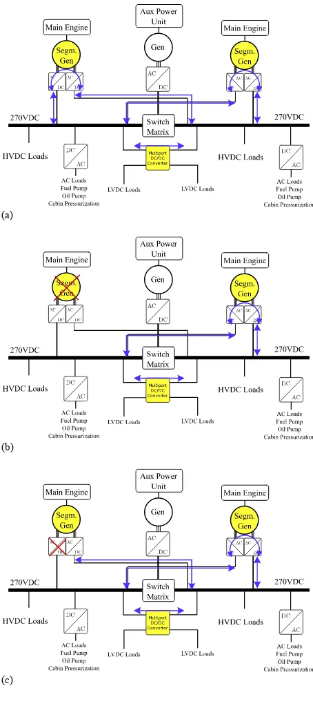
C. Fault torlarance strategies of the combined structure
A ring distribution of electric power is established by the combination of DC/DC multiple active bridge (MAB) converters and DC/AC segmented inverters for starter/generators, where different power flow loops can be created with different fault conditions.
a) The combination may provide full power to the DC bus in common conditions, as shown in Fig. 4(a);
b) The combination may provide 50% up to 100% of full power in condition of any main engine broken, as shown in Fig. 4(b);
c) The combination may provide 75% up to 100% of full power in condition of any segmented inverter broken, as shown in Fig. 4(c).
d) The combination may provide 25% up to 50% of full power in condition of any main engine broken together with another segmented inverter broken, as shown in Fig. 4(d).
(a)
(b)
(d)
Fig. 4. Example of a DC-based EPDS with multi-port power converters in different fault conditions: (a) no fault, (b) main engine or generator fault, (c) segmented inverter fault, (d) main engine or generator fault together with another segmented inverter fault.
D. Communacation considerations of the units
For MEA power distribution systems, optical fibres are used as information path. Optical fibres are point-to-point transmission media. Star-connected information network is one solution of communication and synchronization. The advantage of star-connected network is that the time delay of synchronization is very small, and the module redundancy is easy implemented by disable the gate signal of the H-bridge and bypass the target module.
Although the star-connected information network is well performed, the number of optical fibres is large and it is unfavourable for system modularity. A ring-connected information network is appropriate for the configuration shown in Fig. 2. Number of optical fibres is smaller than star-connected network, but the time delay of synchronization must be calculated while used. Module redundancy could be done by dual-ring-connected networks (both clockwise and anticlockwise).
IV. SIMULATION RESULTS
The simulation model is setup in Matlab/Simulink and PLECS Blockset with one segmented generator and one quadruple active bridge (QAB) converter. The segmented generator is split into two 3-phase systems. Two of the DC ports of the QAB are connected to the rectified segmented inverters, and the other two DC ports are connected to DC loads with different voltage and power.
Table I shows the basic simulation parameters.
TABLE I. SIMULATION PARAMETERS Variables Parameters and units
𝑉 (𝑉 , 𝑉 , 𝑉 , 𝑉 ) 270V, 270V, 28V, 28V
𝐿 , 𝐿 100uH
𝐿 , 𝐿 1.075uH
𝐶 , 𝐶 , 𝐶 , 𝐶 1mF, 1mF, 93mF, 93mF
[image:4.612.62.290.51.210.2]𝑓 20kHz
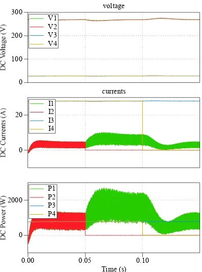
Fig. 5 shows the simulation results of normal operation. It is obvious that the two segmented inverters provides half of the load power. The DC link voltage of the four ports maintain 270V, 270V, 28V and 28V, respectively.
Fig. 5. Simulation results of normal operation (DC voltages, DC currents and DC powers).
Fig. 6 shows the simulation results of one segmented inverter fault (at 0.05s) and then one load converter fault (at 0.1s). After the segmented inverter fault, the remaining segmented inverter will provide full power to the loads, therefore the power between 0.05s and 0.1s will be doubled. After 0.1s, one of the two load abort the system.
Fig. 7 shows the simulation results of and one load converter fault (at 0.05s) and then one segmented inverter fault (at 0.1s). At 0.05s, one of the two load abort the system, then the power of each segmented inverter become half of the normal power. At 0.1s, ). One of the segmented inverters fails, so the remaining segmented inverter will provide full power to the load after 0.1s.
voltage
currents 0
100 200 300
0 10 20 30
Time (s)
0.00 0.05 0.10
0 1000
V1 V2 V3 V4
I1 I2 I3 I4
[image:4.612.316.515.200.462.2]Fig. 6. Simulation results of segmented inverter fault at 0.05s (DC voltages, DC currents and DC powers).
Fig. 7. Simulation results of segmented inverter fault at 0.1s (DC voltages, DC currents and DC powers).
V. EXPERIMENTAL RESULTS
In order to test experimentally the operation of the STRU, especially under a fault condition in a CHB cell, a single-phase prototype is used. The prototype features three CHB cells and a QAB converter, comprising of the high-frequency transformer. Fig. 5 shows the laboratory prototype and Table II lists the parameters.
TABLE II. EXPERIMENTAL PARAMETERS Variables Parameters and units
𝑉 (𝑉 , 𝑉 , 𝑉 , 𝑉 ) 270V
𝑃 3kW
𝐿 , 𝐿 , 𝐿 160uH
𝐿 35uH
𝐿 95uH
𝐶 , 𝐶 , 𝐶 , 𝐶 0.4mF
[image:5.612.316.538.412.545.2]𝑓 20kHz
Fig. 8. Picture of the proposed STRU.
Fig. 9. High frequency waveforms of voltage and current of loaded and unloaded cells of MAB.
VI. CONCLUSION
In this paper, the massive integration of multi-port converters for the electrical power distribution system of the more electric aircraft is proposed. Two technologies are adopted: the multiple-active-bridge DC/DC converter for the interface of the DC bus and the segmented drive concept for the bidirectional DC/AC conversion for the starter/generators. These two power converters allows for the realization of a ring electrical power
voltage
currents 0
100 200 300
0 20
Time (s)
0.00 0.05 0.10
0 2000
V1 V2 V3 V4
I1 I2 I3 I4
P1 P2 P3 P4
voltage
currents 0
100 200 300
0 10 20 30
Time (s)
0.00 0.05 0.10
0 1000
V1 V2 V3 V4
I1 I2 I3 I4
distribution, where the galvanic separation is guaranteed by the windings of the transformers and of the machines, but the whole distribution system can exchange power. This structure shows its resiliency to faults in multiple points and this is demonstrated by simulation results realized on a simplified grid. Preliminary experimental results shows the behaviour of a multiple-active-bridge converter under unbalanced power transfer condition, highlighting the flexibility of the adopted solution.
VII. ACKNOWLEDGEMENT
This work was supported by the Ningbo Science & Technology Bureau under Grant 2013A31012 and Grant 2017D10031; this work was also supported by the China NSFC under Grant 51650110507.
REFERENCES
[1] S. Engel, M. Stieneker, N. Soltau, S. Rabiee, H. Stagge and R. De Doncker, “Comparison of the modular multilevel DC converter and the dual-active bridge converter for power conversion in HVDC and MVDC grids”, IEEE Transactions on Power Electronics, vol. 30, no. 1, pp. 124– 137, 2015.
[2] G. Buticchi, L. Costa, and M. Liserre, “Improving system efficiency for the more electric aircraft: A look at dcdc converters for the avionic onboard dc microgrid,” IEEE Industrial Electronics Magazine, vol. 11, no. 3, pp. 26–36, Sept 2017.
[3] T. Yang, S. Bozhko, and G. Asher, “Functional modeling of symmetrical multipulse autotransformer rectifier units for aerospace applications,” IEEE Transactions on Power Electronics, vol. 30, no. 9, pp. 4704–4713, Sept 2015.
[4] S. Falcones, R. Ayyanar and X. Mao, “A DC-DC multiport-converter-based solid-state transformer integrating distributed generation and storage”, IEEE Transactions on Power Electronics, vol. 28, no. 5, pp. 2192–2203, 2013.
[5] Z. Zheng, Z. Gao, C. Gu, L. Xu, K. Wang and Y. Li, "Stability and voltage balance control of a modular converter with multiwinding high-frequency transformer", IEEE Transactions on Power Electronics, vol. 29, no. 8, pp. 4183–4194, 2014.
[6] P. Wheeler and S. Bozhko, “The more electric aircraft: Technology and challenges.” IEEE Electrification Magazine, vol. 2, no. 4, pp. 6–12, Dec 2014.
[7] J. Chen, C. Wang, and J. Chen, “Investigation on the selection of electric power system architecture for future more electric aircraft,” IEEE Transactions on Transportation Electrification, vol. PP, no. 99, pp. 1–1, 2018.
[8] B. Karanayil, M. Ciobotaru, and V. G. Agelidis, “Power flow management of isolated multiport converter for more electric aircraft,” IEEE Transactions on Power Electronics, vol. 32, no. 7, pp. 5850–5861, July 2017.
[9] C. Gu, Z. Zheng, L. Xu, K. Wang and Y. Li, “Modeling and Control of a Multiport Power Electronic Transformer (PET) for Electric Traction Applications,” IEEE Transaction on Power Electronics, vol. 31, no. 2, pp. 915–927, Feb. 2016.
[10] G. Buticchi, L. F. Costa, D. Barater, M. Liserre, and E. Dominguez, “A quadruple active bridge converter for the storage integration on the more electric aircraft,” IEEE Transactions on Power Electronics, 2018,in press. [11] L. F. Costa, G. Buticchi, and M. Liserre, “Quad-active-bridge dc-dc converter as cross-link for medium-voltage modular inverters,” IEEE Transactions on Industry Applications, vol. 53, no. 2, pp. 1243–1253, March 2017.