May 13, 2004 11:9
Proceedings of DETC’04 2004 Design Engineering Technical Conferences and Computers and Information in Engineering Conference September 28 - October 2, 2004, Salt Lake City, Utah USA
DETC2004–57678
AN APPROACH TO THE SIMULATION OF ROBOTIC SYSTEMS USING XML BASED
CONFIGURATION FILES
Richard Sunderland, Richard Crowder and Bob Damper School of Electronics and Computer Science, University of Southampton, Southampton SO17 1BJ, UK.
Email:{rms02r, rmc, rid}@ecs.soton.ac.uk
ABSTRACT
This paper presents a environment using the eXtensible Markup Language ,XML, to describe a robotic systems in a for-mat suitable for simulation, and to support the integration of sev-eral programming environments to create a flexible physical sim-ulation system. Data exchange via open-standard based plain text files allows the system components to be loosely-coupled, rather than combined them into a single integrated development envi-ronment. This ensures that the most appropriate tools can be used for each component and the system can be extended with mini-mal disruption. Those parts of the system that require real-time data exchange use simpleUNIXsocket-based interactions, which are configured using sharedXMLconfiguration files. The envi-ronment is demonstrated by the simulation of a simple task using aSCARArobot.
Keyword: Robotic simulation, modelling,XML
INTRODUCTION
Although originally designed for large-scale electronic pub-lishing, the eXtensible Markup LanguageXMLhas found a role in supporting the exchange of a wide variety of data over the World-Wide-Web and in other software systems, [1]. In this pa-per we describe the use ofXMLto integrate several software com-ponents for the simulation of a robotic manipulator. The simu-lation includes the robotic manipulator interacting with its en-vironment, together with the manipulation of a range of objects (e.g., cube, sphere). The flexibility ofXMLensures that this
ap-proach is equally applicable to other physical simulations where there is a need to describe complex multi-jointed, multi-actuated mechanical systems, for example a walking robot.
Our previous work [2, 3], has leading to a development of a number of dexterous end effectors and sensors. As part of this activity we have need for a high fidelity simulation environment, that is capable of accurately modelling the physical interaction between the grasped object, a multi-fingered end effector, and its serving manipulator. One of the most significant challenges in robotics is the grasping of the object in an unstructured environ-ment, where the object’s parameters are not known a priori and the sensory information is subjected to uncertainty. We have de-veloped a neurofuzzy control approach to this problem, [4]. In order to validate this approach we need to fully simulate the con-trol system, together with the physics of the robotic manipulator, its sensors and in particular its interaction with the environment. Our current research aims to add to the understanding of manipulation with the objective of developing advanced manip-ulators. Inspiration will be drawn from biological and synthetic studies, although cross fertilization will be likely, the overall ob-jective is the development of real world systems.
SIMULATION
Geometric modelling with or without simulation is of con-siderable importance in the design and development of robotic systems, typical application areas include, [5]:
1. Provision of a research environment where novel control techniques can be validated before being used on an actual
robotic system. This approach ensure that expensive hard-ware is not exposed to damage if the control laws imple-mented are incorrect.
2. Design and testing of the manipulator to ensure that it is capable of satisfying the design specifications.
3. Using the modelling environment to resolve problems with the interacting between robots and plant in a manufacturing process.
4. Following simulation the actual paths and other variables can be passed to the real robot for execution of the task. 5. Telerobotic user interface; if the actual workspace can not
be accessed, a simulation can be used to provide direct user feed back to the operator.
To prove successful, a simulation environment needs to pro-vide the following features:
1. Run time storage of simulation objects.
2. Dynamics models that update the state of the simulation ob-jects.
3. A suitable interface to monitor the progress of the simula-tion.
4. A flexible controller environment, allowing the comparison of different control strategies with minimum reprogramming effort.
5. Tools for editing simulation objects off-line.
6. A structured method of configuring simulation options. 7. Flexibility in capturing output data, including files and
im-ages for subsequent analysis.
8. Complete system scriptablility to maximise flexibility of the simulations being undertaken.
Robotic systems have two features that lend themselves well toXML descriptions: a hierarchical structure and a large num-bers of parameters. Although it would be possible to describe a manipulator as a single list of joints, body parts, sensors and actuators, such a list would have to be accompanied by consid-erable extra information defining how these elements are inter-connected. Also, this information would have to be checked and corrected whenever the structure was modified. More gen-erally, robotic simulations requires a large number of parame-ters which need to be stored in a standardized machine-readable fashion, that will allow the manipulator and its environment to be moved between the simulation and other applications, including, for example, Finite Element Modeling and CAD systems. This is achievable asXMLprovides a means by which these data can be hierarchically structured and clearly linked to the objects de-scribed and easily coupled with metadata that adds physical units (e.g., millimeters, Newtons) and labels where required.
ROBOTIC MODELLING
One of the most widely used approach to robotic analysis is based on the Denavit-Hartenberg (DH) descriptions, [6]. These descriptions have a very limited structure: a list of the joint-link pairs, each with four parameters. This approach provides a com-pact and flexible approach to modelling the kinematic structure of the manipulator. However, the DH parameters in its basic form does not provide an accurate description of the physical attributes of the robot, in that they do not contain information regarding actuator specification, physical link shape, joint characteristics and sensor placement. The DH descriptions of a manipulator’s kinematic structure does however have several properties that fa-cilitate mathematical analysis, but since we are undertaking re-quires fully-featured physical simulation, these properties are not especially useful in this work. AMATLABtoolbox [7] is readily available that will handle joint-link based simulations directly. However, it currently does not perform collision detection and is therefore unsuitable for simulation of manipulators and their direct interaction with their environment.
Robotic grasping and manipulation is a well researched area [8, 9, 10]. In many cases the results are supported by modelling and/or simulation, concerned with force or form closure, and the interaction between the object and a dexterous end effector. In order to simulate the interaction between the object, end-effector and manipulator, a full physics model is required, we selected Vortex1. Vortex is a powerful dynamics engine, based on funda-mental Newtonian physics. It enables application developers to build physically accurate motion and object interaction for real time simulation applications. The software features, stable rigid-body dynamics, an accurate collision detection and collision re-sponse capability, multiple joint types with motors and associ-ated constraints, and the capability for high-fidelity vehicle dy-namics.
It should however be recognised that there are a number of other robotic simulation environments available, however these are either tailored toward mobile robotics and path-finding, mak-ing them less suitable for simulation of manipulation tasks, [11, 12] or are in the early stages of development, [13]. Where real-time rigid body simulation is performed by these systems, the Open Dynamics Engine [14] is used instead of the Vortex sim-ulation libraries. A simsim-ulation environments such as GraspIt!, [15], is capable of performing the simulations required, but does not give us the flexibility required for control algorithm develop-ment. If the robot is to be simulated in a manufacturing environ-ment a package such as WorkSpace [16] can be used.
SIMULATOR FOR PHYSICAL SYSTEMS
To support our research in robotic manipulation, we need to simulate the accurate, real-time dynamics of physical hardware,
1Supplied by CMLabs, Montreal, Quebec, Canada.
Figure 1. Block diagram of the developed simulation environment which combines several different software components.
Sphere Manipulator
LINKCHAIN finger 1
LINKCHAIN finger 2 Slip sensor
Phlange2.1
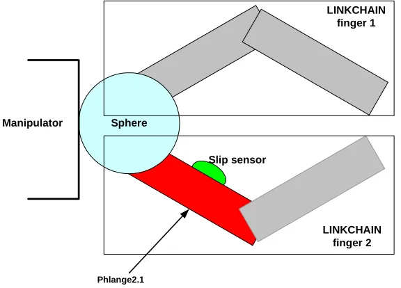
Figure 2. A two fingered end effector which is described by the configuration files detailed in Figures 3 and 4
including the manipulator, end effector and their interation with the environment, with a requirement for flexible and intelligent control actions. Also, to decrease development time, we want to minimise the amount of bespoke code by exploiting proprietary, commercial software. We therefore need a framework which can couple together the different proprietary software components.
Figure 1 shows a block diagram of the developed simula-tion environment. Two commercial packages were used — Vor-tex Simulation Libraries and MATLAB — together with a be-spoke C++ object hierarchy that mirrors the manipulator struc-ture. Vortex has extensive documentation, and is easily inte-grated with other libraries to create powerful simulation
[image:3.595.164.452.379.586.2]grams.MATLABis the industry standard package for rapid math-ematical algorithm prototyping, especially for control applica-tions. In addition Python2is used for scripting. A lightweight OpenGL/DirectX viewer supplied with Vortex was considered adequate for this work.
Configuration Files
A suitable approach to describe the robotic system is pro-vided by Vortex, which provides a methodology to load and store simulation objects directly from XML files. However, Vortex’s XML files do not allow any structuring or labeling information (e.g, joint names, for example ‘wrist’) to be stored and made available to other system components, includingMATLABwhich is used to model the joint and system controllers. To resolve this problem we have developed our own XML definition structure to describe the robot in its environment.
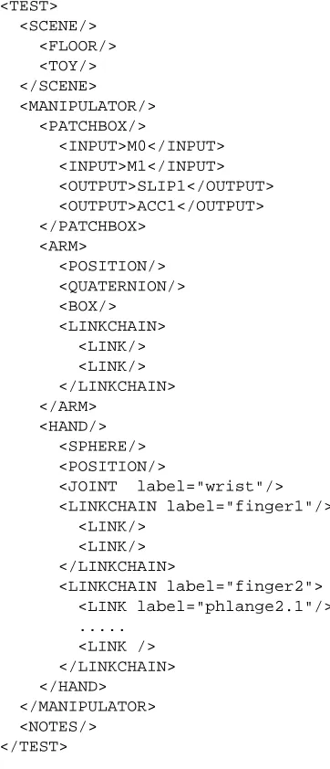
An overview of theXMLconfiguration file is shown in Fig. 3, and should be compared with outline of the end effector shown in Fig 2. For clarity the majority of the the detail has been re-moved from the snippet. TheSCENEelement contains all the ele-ments of the system that are not part of the robot being tested, in-cluding the floor and the target objects. TheMANIPULATOR con-tains three sections; PATCHBOX, ARMandHAND. ThePATCH
-BOXdefines the order in which the manipulator’s various input and output signals are sent and received over theUNIX socket. The robot is fully described inARMandHAND, as a number of linkchains consisting of a number of interconnected links. In this example theSPHEREobject is used as the palm of the end effec-tor.
Figure 4 details the parameters for an individual link entry, in this case the upper link ofLINKCHAIN‘finger 2’ of theHAND, termed phlange2.1. The elementsPOSITIONandQUATERNION
specify the initial position and orientation for this link, in the axis-frame of the previous link. TheBOXentry defines the link’s geometry; the mass and polar moment of inertia are calculated using by the Vortex libraries. TheJOINTentry specifies the axis and range of movement permitted between this link and the pre-vious link, with the option of storing motor parameters. Each link can have a number ofSENSORelements, with their position defined in the axis-frame of the link. In this case a slip sensor is defined. As this sensor is not standard in Vortex, it was modeled by considering the relative positions of the point of contract of the finger with reference frame of the grasped object.
The simulation is based on a family of C++ objects. At con-figuration time, these objects parse anXMLfile usinglibxml2
and store the results in standard template library container classes. By usinglibxml2, we reduce coding and debugging time and will benefit from future releases. At the same time,
XMLallows us to exploit standard tools to write, modify and ver-ify the simulation description files, which can be used easily by
2http://www.python.org/doc/
<TEST> <SCENE/>
<FLOOR/> <TOY/> </SCENE> <MANIPULATOR/>
<PATCHBOX/>
<INPUT>M0</INPUT> <INPUT>M1</INPUT> <OUTPUT>SLIP1</OUTPUT> <OUTPUT>ACC1</OUTPUT> </PATCHBOX>
<ARM>
<POSITION/> <QUATERNION/> <BOX/>
<LINKCHAIN> <LINK/> <LINK/> </LINKCHAIN> </ARM>
<HAND/> <SPHERE/> <POSITION/>
<JOINT label="wrist"/> <LINKCHAIN label="finger1"/>
<LINK/> <LINK/> </LINKCHAIN>
<LINKCHAIN label="finger2"> <LINK label="phlange2.1"/> ...
<LINK /> </LINKCHAIN> </HAND>
[image:4.595.320.501.88.509.2]</MANIPULATOR> <NOTES/> </TEST>
Figure 3. TheXMLconfiguration file used to define a robot and end effector in the simulated environment. The details of ‘phlange2.1’ are expanded in Fig. 4.
all stages of the system. It is expected that future simulations will requires large amounts of binary data ( for example height fields or vertex meshes), in these cases external files will be referenced rather than included the data directly.
Socket Interface
A separate Vortbased client was developed that would ex-ecute the physical simulation while interacting with aMATLAB -driven controller, via aUNIX-socket. MATLABprovides a direct interface to C++, via late linked pre-compiled binary files (MEX -files). These files have access to theMATLABwork space, and
<LINK label="phlange2.1">
<POSITION z="50.0" x="30" />
<QUATERNION angle="180" ux="0" uy="0" uz="1"/>
<BOX length="50" width="10" depth="10" density="0.1" /> <JOINT linear="true" axis="x" label="J7">
<UPPERLIMIT damping="5000" stiffness="1000" range="0" /> <LOWERLIMIT damping="5000" stiffness="1000" range="-35" /> <MOTOR maxforce="0.01">M7</MOTOR>
</JOINT>
<SENSOR logged="true" gain="1.0" label="SLIP2" size="10" type="slip"> <POSITION x="5" y="0" z="20"/>
</SENSOR> </LINK>
Figure 4. TheXMLdescription of an individual link. The parameter’s units are defined earlier in the XML file.
share its file descriptors. It should be noted that the file descriptor numbers provided withinMATLABdo not map directly to those in the operating system, in our case Linux, and so care must be taken when sharing descriptors betweenMEX-files and standard
MATLABM-files. EachMEX-file is loaded, run and then removed from memory, so any state information required must be loaded from theMATLABworkspace and, stored before termination.
The link provided by the socket contains a stop byte fol-lowed by a block of floating point values (either actuator or trans-ducer signals, depending on direction of the signal flow). Al-though this limits the communication options available, it has the advantage of ensuring that the controller is only presented with information that it could reasonably gain from a real robot. The test configuration file provides the option to label each actu-ator and transducer. It also includes aPATCHBOXelement, which contains a list of input and output labels. After loading a test con-figuration, the simulation environment scans through thePATCH
-BOX, looking for matches between the labels specified there and those in the rest of the file. It then presents and receives the information in the order given in thePATCHBOX, and forwards the information appropriately. This gives the test designer com-plete control over which inputs/outputs are transmitted over the socket, over their order, and also allows MATLABto configure itself appropriately.
Scripting
For our purposes, it is an essential that the system can run multiple tests unattended. Three operations must be undertaken for this to happen. First, a range of pprocessing tools are re-quired for the generation of valid and variableXMLtest descrip-tions. Second, a further set of post-processing tools should be able to take the results logged by the simulation run and extract useful metrics from them. Third, a set of tools to coordinate the pre- and post-processing activities to create a series of simula-tions.
It is therefore important that the input files can be easily modified by automated scripts and that the output can be properly
interpreted. Python has been chosen for this because it facilitates clear readable code through its modular name-spacing and rigid source code layout. It already has well-developed support for
XML parsing and generation and so was easy to integrate into the system. The physical simulation is used (with the output dis-abled) to parse the robotXMLfiles when processing is required. This means that the same input parsing code is reused, reducing maintenance time.
System Overview
The main component of our system is the Manipulation Simulation Client (MaSC) which provides a wrapper around the commercial dynamics and collision library, Vortex. On execution the MaSC loads a Test Specification File (TSF), builds a
simula-tion from the Vortex components and creates aUNIXlocal socket
though which it can exchange actuator demands and sensor read-ing. MaSC is written in C++ and will be easily extensible in the future. A Document Type Definition (DTD) has been written for theTSFs. This allows for independent validation and faster, more controlled, editing in packages such as Xeena3.
Two harness have been written that facilitate connection to the MaSC from C/C++ andMATLAB. These also process theTSF
file to calculate the appropriate number of actuators and sensors. These may be extended to extract more detailed labelling infor-mation from theTSFs if this becomes useful and theTSFs format settles down enough for this to become practical. We has written individual robot joint controllers in both C andMATLABto prove the connection to the MaSC via the appropriate harnesses. In the simulation presented in this paper the proportional joint-position controller was implemented inMATLAB, however this will be re-placed by other control strategies as part of our ongoing research. Two Python support scripts have been developed. The first generates a fully wired patch box for a Manipulator or com-bines a Arm and a Hand to generate a Manipulator (withPATCH
-BOX). The second takes the (XML based) output generated by
3http://www.alphaworks.ibm.com/tech/xeena
the MaSC and extracts comma-separated-variable files. These are more compact and easily imported into other packages, for either further processing or graphing. The only disadvantage of this approach is that labelling inherent in the original format is nor preserved.
SIMULATION OF A ROBOT
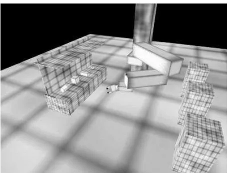
The developed system runs on a standard 2.4GHz Intel desk-top with a NVIDA graphics card running a standard install of RedHat 8.0.
To demonstrate the performance of the simulation en-vironment we drove a model of a SCARA robot through a five stage, pick and drop activity (lower, grip-object,
tilt-wrist, raise-arm, release). The developed model was based on aRTX SCARArobot, a small industrial robot capable of handelling loads of up to 2Kg at 100mm s−1. Figure 5 shows screen shots of the robot in its test environment, prior to picking up an object.
In this simulation a simple proportional joint-position con-troller based on the actual robot’s control algorithms was imple-mented inMATLAB. The end effector’s control was again pro-portional using slip and force sensors developed in house.
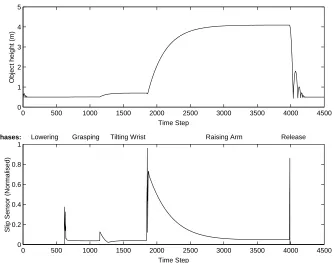
After completing the simulation, the Python script extracts comma-separated-variable files from theXMLoutput log. These files were imported intoMATLABand used to generate the results presented in Figure 6.
As expected the slip is a function of the robot’s orientation and acceleration, together with the gripper’s contact forces. The increase in slip at 600 time steps indicates that the object has been picked up by the robot’s end effector. As the robot’s speed and orientation is changes, their is a corresponding increase in measured slip, which is used to control the grip force, and main-tain a stable grasp. When the object is released from the jaws, it fall to the ground, and bounces. The bounce is clearly visible on the upper plot, together with the object’s slip relative to the end effector as it is released.
This simple simulation demonstrates the features of our ap-proach in that:
1. A task can be programmed into the simulation.
2. The full physics of the robot, sensors, grasped object and environment can be modelled.
3. Results can be presented both as graphics and images (both moving and still)
CONCLUDING REMARKS
This paper has discussed the development of a simulation environment that will provide a flexible tool for the ongoing re-search into robotic systems at the University of Southampton. The systems being simulated are configured using XML files.
(a) The simulatedSCARArobot in its test environment. The object be-ing picked up is the block on the bench
[image:6.595.334.562.85.258.2](b) A close up of the simple two fingered end effector. The sensors are shown at the end of the finger tips
Figure 5. Screen shots generated during the simulation
This approach provides a number of benefits, firstly the hierar-chical structure of theXMLmaps directly onto the physical de-scription of a robotic manipulator, secondly the use of a loosely coupled architecture allows us to explore various control op-tions, without modifying the physical simulation. Our prelimi-nary evaluations has shown that the system provides the required flexibility.
ACKNOWLEDGEMENT
The authors wish to thanks the School of Electronics and Computer Science, University of Southampton, for providing a research scholarship for Richard Sunderland.
0 500 1000 1500 2000 2500 3000 3500 4000 4500 0
0.2 0.4 0.6 0.8 1
Time Step
Slip Sensor (Normalised)
0 500 1000 1500 2000 2500 3000 3500 4000 4500
0 1 2 3 4 5
Time Step
Object height (m)
Grasping Tilting Wrist
Lowering Raising Arm Release
[image:7.595.142.476.88.351.2]Phases:
Figure 6. Pick-up and release cycle from simulation of the SCARArobot fitted with a parallel motion jaw. Height of target object in metres (top) and normalised jaw slip sensor reading (bottom).
REFERENCES
[1] T. Bray, J. Paoli, and C. M. Sperberg-McQueen. Extensi-ble markup language (XML) 1.0. Recommendation, W3C,
http://w3c.org/xml/, February 1998.
[2] P Chappell, M Fateh, and R Crowder. Kinematic control of a three-fingered and fully adaptive end-effector using a jacobian matrix. Mechatronics, 11:355–68, 2001.
[3] V Dubey, R Crowder, and P Chappell. Optimal object grasp using tactile sensors and fuzzy logic. Robotica, 17(6):685– 693, 1999.
[4] J.A. Dom´ınguez-L´opez, R.I. Damper, R.M. Crowder, and C.J. Harris. Hybrid neurofuzzy online learning for optimal grasping. In Proceedings of IEEE International Conference on Machine Learning and Cybernetics 2, pages 803–808, Xi’an, China, 2003.
[5] C Mirolo and E Pagello. A solid modelling system for robot action planning. IEEE Computer Grapgics and Applica-tions, pages 55–69, Jan 1989.
[6] J. Denavit and R. S. Hartenberg. A kinematic notation for lower-pair machanisms based on matrices. Applied Me-chanics, pages 215–221, 1955.
[7] P Corke. A robotic toolbox for MATLAB. IEEE Robotics and Automation, 3(1):24–32, March 1996.
[8] C. Bard, J. Troccaz, and G. Vercelli. Shape analysis and
hand preshaping for grasping. In Osaka, Japan, Interna-tional Workshop On Intelligent Robots and Systems, 1991. [9] M Cutosky. Grasp models and the design of hands for man-ufacturing tasks. IEEE Transactions on Robotics and Au-tomation, 5(3), June 1989.
[10] A. Okamura, N. Smaby, and M. Cutkosky. An overview of dexterous grippers. In Proceedings of the Robotics and Au-tomation Conference, San Francisco, pages 255–62, April 2000.
[11] Gazebo. Outdoor multiple robot simulator,
http://playerstage.sourceforge. net/gazebo/gazebo.html.
[12] DynaMechs. Multibody dynamic simulation library,
http://dynamechs.sourceforge.net/.
[13] OpenSim. 3d simulator for autonomous robots,
http://opensimulator.sourceforge.net/.
[14] Open Dynamics Engine.
http://www.opende.sourceforge.net/. [15] A Miller. Graspit! A Versatile Simulator for Robotic
Grasping. PhD thesis, Department of Computer Science, Columbia University, New York, June 2001.
[16] Workspace Robotic Simulator. http://www.workspace5.com.