FACULTY OF ELECTRICAL ENGINEERING
DEVELOPMENT AND CONTROL OF EXOSKELETON (UPPER LIMB) FOR MOBILITY SUPPORT
MUHAMMAD IZZ BIN ZAMLUS
BACHELOR OF ELECTRICAL ENGINEERING (CONTROL, INSTRUMENTATION AND AUTOMATION)
DEVELOPMENT AND CONTROL OF EXOSKELETON (UPPER LIMB) FOR MOBILITY SUPPORT
MUHAMMAD IZZ BIN ZAMLUS
A report submitted in partial fulfillment of the requirements for the degree of Bachelor in Electrical Engineering (Control, Instrumentation and Automation) with
Honours
Faculty of Electrical Engineering
UNIVERSITI TEKNIKAL MALAYSIA MELAKA
APPROVAL
I hereby declare that I have read this dissertation/report and in my opinion this dissertation/report is sufficient in terms of scope and quality as a partial fulfillment Bachelor of Electrical Engineering (Control, Instrumentation & Automation).
DECLARATION
I declare that this thesis entitled “Development and Control of Exoskeleton (Upper Limb) for Mobility Support” is the result of my own research except as cited in the references. The thesis has not been accepted for any degree and is not concurrently submitted in candidature of any other degree.
ABSTRACT
ABSTRAK
ACKNOWLEDGEMENT
TABLE OF CONTENTS
CHAPTER TITLE PAGE
APPROVAL DECLARATION
ABSTRACT i
ABSTRAK ii
ACKNOWLEDGEMENT iv
TABLE OF CONTENTS v
LIST OF TABLE vii
LIST OF FIGURE viii
LIST OF APPENDICES x
1 INTRODUCTION 1.1 Project Background 1
1.2 Motivation 2
1.3 Problem Statement 3
1.4 Objective 4
1.5 Scope 5
1.6 Organization of Thesis 6
2 LITERATURE REVIEW 2.1 Mobility Assistive Robot Based Human Arm 7
2.2 Degree of Freedom (DOF) of Human Arm 8
2.3 Modelling of Human Arm 10
2.4 Automation Model using Solidworks Software 12
2.5 Automation Model using MATLAB Software (Simmechanics) 14
2.6 Proportional-Integral-Derivative (PID) Controller 16
2.7 Proportional –Derivative (PD) Controller 19
2.8 Ziegler-Nichols Tuning Technique 19
2.9 Summary 21
3 METHODOLOGY 3.1 Project Methodology 22
3.2 Design Human Arm Model 25
3.3 Transfer Human Arm Model from Solidworks to MATLAB Simulink via Simmechanics 32
3.4 Design and Develop Controller of Human Arm Model 34
3.4.1 Obtaining Human Arm Model Transfer Function 40
3.4.2 Ziegler-Nichols Tuning Techniques 41
CHAPTER TITLE PAGE
4 RESULT AND DISCUSSION
4.1 Human Arm Model Design 52
4.2 Importing Human Arm Model via Simmechanics 54
4.3 Develop and Design Control System of Human Arm Model 61
4.3.1 The performance of controller and controller error on human arm model joints 65
4.3.2 The comparison of performance controller trajectory and error on the human arm joints for 𝐾𝑢 = 1 75
4.3.3 The comparison of performance controller trajectory and error on the human arm joints for 𝐾𝑢 = 2 78
4.4 Discussion 80
4.5 Summary 81
5 CONCLUSION 5.1 Conclusion 83
5.2 Future Works 85
REFERENCES 86
LIST OF TABLE
TABLE TITLE PAGE
2.1 Human Arm Joint Movement 10
2.2 Effects of PID controller 18
2.3 PID controller parameters by Ziegler-Nichols Method 20
3.1 Parameter of Human Arm Model 31
3.2 Parameter of Open-Loop Ziegler Nichols Tuning method 43
3.3 Parameter of Closed-Loop Ziegler-Nichols Tuning methods 45
3.4 Trajectory of human arm joint 46
3.5 Tuning parameters of PID controller and PD controller 47
4.1 Parameter of Ziegler-Nichols (Z-N) Tuning Method 63
4.2 The (Z-N) tuning value on shoulder joint for 𝐾𝑢 = 1 65
4.3 The (Z-N) tuning value on elbow joint for𝐾𝑢 = 1 68
4.4 The (Z-N) tuning value on shoulder joint for 𝐾𝑢 = 2 70
4.5 The (Z-N) tuning value on elbow joint 𝐾𝑢 = 2 72
4.6 Data of PID and PD controller for 𝐾𝑢 = 1 75
4.7 Data of output error of PID and PD controller for 𝐾𝑢 = 1 77
4.8 Data of PID and PD controller for 𝐾𝑢 = 2 78
LIST OF FIGURE
FIGURE TITLE PAGE
1.1 Scope of the Project 5
2.1 7 DOF in a human arm 9
2.2 Four basic degrees of freedom of the arm 9
2.3 Geometric parameters of human artificial arm 11
2.4 A CAD model of articulated robot in Solidworks 14
2.5 Simmechanics diagram created in Simulink 15
2.6 Block diagram of PID controller 17
3.1 Flow chart of the project 24
3.2 Solidworks 2015 software 25
3.3 Example of body part design 26
3.4 Complete design of body part 26
3.5 Design of the box part 27
3.6 Development of the shoulder joint 28
3.7 Design of the knuckle pin part 29
3.8 Design of knuckle joint 30
3.9 Human arm model 30
3.10 MATLAB and MATLAB Simulink 32
3.11 Model is import to MATLAB 33
3.12 Simulink output of human arm model 33
3.13 Model is run in Simulink 34
3.14 Subsystem of the controller 36
3.15 PID Controller in Subsystem 37
3.16 Human Arm Model System 38
3.17 Steps to design the controller 39
3.18 Open-loop output linear points on shoulder joint 40
3.19 Closed-loop system on shoulder joint 41
3.20 Reaction Curve 42
3.21 Initial response of elbow joint 46
3.22 An example response of PID controller on elbow joint for 𝐾𝑢 = 1 47
3.23 An example response of PD controller on elbow for 𝐾𝑢 = 1 48
3.24 An example of elbow trajectory of both controllers for 𝐾𝑢 = 1 48
3.25 Response error of PID controller on elbow for 𝐾𝑢 = 1 49
3.26 Response error of PD controller on elbow 1 for 𝐾𝑢 = 1 50
3.27 An example of elbow error for 𝐾𝑢 = 1 50
4.1 Exploded view of human arm model parts 53
4.2 Human arm model 54
4.3 Imported of one arm model 56
FIGURE TITLE PAGE 4.5 Arm model Simulink output an
additional blocks (PD Controller) 59
4.6 Arm model Simulink Output and additional blocks (PID Controller) 60
4.7 Controller in Subsystem 61
4.8 Initial response of the joint 62
4.9 PID controller division 63
4.10 The trajectory of shoulder joint for 𝐾𝑢 = 1 65
4.11 Trajectory error of shoulder joint for 𝐾𝑢 = 1 66
4.12 Trajectory of elbow joint for 𝐾𝑢 = 1 68
4.13 Trajectory error of elbow joint for 𝐾𝑢 = 1 69
4.14 Trajectory of shoulder joint for 𝐾𝑢 = 2 71
4.15 Trajectory error of shoulder joint for 𝐾𝑢 = 2 72
4.16 Trajectory of elbow joint for 𝐾𝑢 = 2 73
4.17 Trajectory error of elbow joint for 𝐾𝑢 = 2 74
LIST OF APPENDICES
APPENDIX TITLE PAGE
CHAPTER 1
INTRODUCTION
This chapter describes the mobility support of the exoskeleton (upper limb). The project emphasizes on the development and control of assistive exoskeleton which is upper limb part for mobility support. The project brief’s explanation will be explain in the project background. The problem statement and motivation relating to this project will be explain in this chapter .Finally, objective and scope are listed accordingly.
1.1Project Background
Exoskeleton used to support and defends human or animal’s body [1]. The region in an animal extending from the deltoid region to the hand, including the arm, axilla and shoulder called as upper extremity [2]. The upper limb enables to grip, write, lift and throw among many other movements. The upper limb has been shaped by evolution, into a highly mobile part of the human body. The upper limb has developed for stable mobility support. This project focuses on the development of assistive human robot arm which is suitable for mobility support. Human arm refers to the structures part extended from shoulder to the elbow.
The movement of the upper limb or upper extremity will be control using Proportional-Integral -Derivative (PID) and Proportional-Derivative (PD) controller. PID controller are common technologies used nowadays in order to design a controller. PD is a controller type which is from PID division. The other controller type from PID is Proportional-Integral (PI) controller. The PID controller only able to control low torque and speed which is can be define as simple system and it using manual panel of controller interface. PID controller are design to eliminate the need for continues operator attention. The integral term is most effective at low frequencies, the proportional term are at moderate frequencies and integral term are at high frequencies. The profits from the integral term is the reduction of steady state error and the differential term improve the receptiveness stability.
The project presents about the development and control of exoskeleton (upper limb) for mobility support. An assistive robot arm is created to test and develop a mobility support. The project focuses on the movement of human arm. The aim is to help injured and disabilities people to move their arm. People with these problems are the main subject for this project.
1.2Motivation
of model in related software enable engineers to investigate the movement of the model through the simulation in the controller software. Complete control system will be develop. It will benefit a lot since it use in the term of instrument and control engineering perspective.
1.3Problem Statement
Strokes and arm injuries are the most factor that affects the movement of arm nowadays. Approximately 15 million people worldwide have a stroke each year. In a worldwide population, around 1 in 6 people in this world have a stroke in their lifetime [4]. Other than stroke, arm injuries are caused by cuts and laceration injuries. U.S. Bureau of Labor Statistics (BLS) reports that cuts and laceration injuries are the most common work injuries to the hands. The victims to the incidents accounted for 4,120 job transfer or restriction cases in 2012 [5].
In order to solve above problem, a mechanism was created to help affected people to move. So, the development and control of exoskeleton (upper limb) for mobility support has chosen in this project. This project is use to help people with minor stroke and arm injuries to move their affected body part to normal movement. So, the project is done by designing a wearable assistive arm model to activate disabilities arm. Next, if the patient is suitable to use the assistive model, it can train the arm to move in the good posture.
1.4Objective
The project to be developed is to fulfill the configuration and specification of development and control of upper limb or human arm. An assistive human arm model should be develop in the beginning part of the project. Due to shortage of budget, the human arm are able to design using the software tools The software tools that are used in this project is CAD software, Solidworks and simulation software, MATLAB.
The objectives of this project are used as a benchmark to make sure the progress can be carried properly. The “Development and Control of Exoskeleton (Upper Limb) for
Mobility Support” project objectives can be defined as listed below:
1. Design human arm model using CAD software, Solidworks and transfer to MATLAB via Simmechanics.
2. Develop and design control system of human arm model using Proportional-Derivative (PD) controller and Proportional-Integral-Proportional-Derivative (PID) controller using simulation software, MATLAB.
1.5Scope
In order to accomplish the objective of this project and enhanced the effectiveness of this system, few scopes has been considered. The scope of this project is to develop and control the upper extremities exoskeleton that can interfaced using Solidworks and MATLAB software. The scopes are shown as the flowchart in the figure 1.1:
Figure1.1: Scope of the project
[image:20.612.96.542.232.279.2]1.6Organization of Thesis
The organization of this report is arrange as below:
Chapter 2,Literature Review: This chapter discuss the article of the current and
previous research to enhance an idea to do the project
Chapter 3, Methodology: Methodology is one of the chapter discuss the process
path of the project until the objectives is achieved. In this chapter, the development of this project is written from designing of human arm in Solidworks until the analysis of human arm movement in the MATLAB.
Chapter 4, Result and Discussion: This chapter shows result of software
development and simulation of human arm. In this chapter, the result are also based on objectives stated in the chapter 1.This project will show the result from designing of human arm model, transferring the model via Simmechanics. Finally, testing and simulation of human arm model in MATLAB. The analysis of human arm model is discuss in this chapter as well. The model is analyze based on its trajectory value and error. The value of the arm model trajectory will be discussed as well in this chapter.
Chapter 5, Conclusion: This chapter summarize all the project flow from
CHAPTER 2
LITERATURE REVIEW
In this chapter, the mobility assistive robot based human arm will be first topic to review. In order to develop the upper extremities, degree of freedom and modelling of human arm are also review in this chapter. Phases to develop human arm by using Solidworks and MATLAB will be clarify in the development of automation modelling part. Finally, the basic concept of PID controller is presented as well in this chapter.
2.1 Mobility Assistive Robot based Human Arm
robot provides 7 degree-of- freedom (DOF) motion. The robot runs as a subject to an inherent mapping between the 7 DOFs of the robot arm and the 4 DOFs of the human arm [8].
The mobility assistive robot is focuses on the development of arm robot. The movement of the arm robot are referring to the human arm.
2.2 Degree of Freedom of Human Arm
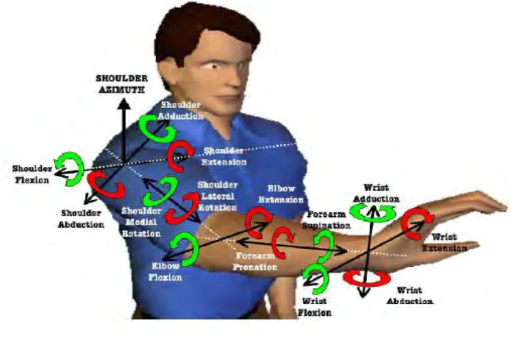
Figure 2.1: 7 DOF in a human arm [9].
The human arm have an abilities to move into basic four degrees of freedom (4 DOF).Four Degrees of freedom includes the shoulder abduction / adduction. Shoulder flexion / extension and internal / external rotates as well as the elbow flexion / extension motion [10]. Four basic degrees of human arm are shown in figure 2.2.
[image:24.612.96.553.480.662.2]