Int. J. Electrochem. Sci., 11 (2016) 359 - 373
International Journal of
ELECTROCHEMICAL
SCIENCE
www.electrochemsci.org
Application of the Convective Diffusion Equation with
Potential-Dependent Boundary Conditions to the Charge
Transfer Problem in Four-Electrode Electrochemical Cell on the
Condition of Small Hydrodynamic Velocity
Vadim M. Agafonov*, Egor V. Egorov, Alexander S. Bugaev
Moscow Institute of Physics and Technology, Institutsky Lane 9, Dolgoprudny, Moscow Region, 141700.
*
E-mail: [email protected]
Received: 4 October 2015 / Accepted: 9 November 2015 / Published: 1 December 2015
To describe charge transfer in a four-electrode electrochemical cell for the Iodide-Iodine redox system, the Nernst-Plank equations and the boundary conditions based on the kinetics of the reactions on the electrodes have been modified, assuming the small active component (I3) concentration relative to the background electrolyte concentration (components Iand metal ions Me). The resulting mathematical model comprises the convective diffusion equation and the Laplace type equation for the potential, while the boundary conditions on the electrodes bond the potential and the concentration of
3
I . The approach was applied for the classical one-dimensional model in case of small hydrodynamic velocity. For realistic parameters of the system, the modelling results are different from the solution of the convective diffusion equation with the fixed concentration on the electrodes and are in good agreement with the experimental data.
Keywords: Ion transport, convective diffusion, sensors, electrode kinetics, hydrodynamics.
1. INTRODUCTION
transfer) sensor. Electrochemical sensors are used in seismology, seismic exploration, perimeter security systems, structural monitoring etc [1], [3], [4], [5], [6], [7], [8].
Such sensors most frequently contain concentrated water based iodide solution with small amounts of molecular iodine in the form of tri-iodide ions. Due to high concentration and high dissociation of iodide, the solution conductivity is usually high, which results in negligibly weak electrical field in the solution. This fact allows to use a convective diffusion equation to determine tri-ioide ions concentration as the most common and convenient approach to model charge transfer in the signal converting cell. The obvious advantage of convective diffusion equation is the simplicity of mathematical formulation which makes it possible to find analytical solution of the charge transfer problem in many cases [9], [10]. For numerical methods, the use of the convective diffusion equation [11], [12] significantly lowers the computation resources requirements . However, there are certain technical difficulties and fundamental limitations of such approach. As discussed in [13], [14], it is almost impossible to formulate boundary conditions on anodes correctly, even in case of saturation current. Another limitation of the convection diffusion approach is that it is unable to describe natural convection adequately since there is only one type of ions under consideration in the convective diffusion approximation. All presented ions yet make approximately the same contribution into the density variations that are the fundamental reason of natural convection. That is why, much more complicated numerical methods based on Nernst-Plank equations with the Buttler-Volmer type boundary conditions have been widely used in recent years [15]–[17], [2], [18].
The aim of this paper is to combine convective diffusion equation with a more accurate formulation of boundary conditions. The theoretical model starts from the Nernst-Plank equations and the boundary conditions which take into account electrochemical kinetics of the reaction on the electrodes of signal converting cell. Assuming small active component (I3) concentration relative to background electrolyte concentration (components Iand metal ions Me), both equations and the boundary conditions were significantly simplified. The resulting mathematical model includes convective diffusion equation and the Laplace type equation for electrochemical potential. It is much simpler than the original one and could be solved analytically for many configurations. At the same time, unlike the original convective diffusion equation, this model takes into account the mutual influence of the potential and tri-iodide concentration on the electrodes of signal converting cell.
The proposed model was applied for the classical [19] one-dimensional signal converting system. Unlike the original Larkam’s model, the concentration of tri-iodide ions on anodes was not constant. Different frequency behavior for both anodic and cathodic currents were thus found. The comparison of the theoretical modelling results with the experimental data taken from [14] showed good correlation between them.
2. THEORY
K and negative Iions. Iodine
I
2 is present in the form of tri-iodide ions I3. The electrodes are made from platinum or platinum alloys. The modelling is aimed to find the inter-electrode currents variations as the result of liquid motion. In turn, the cell is used as a sensitive element of inertial sensor. The liquid motion is initiated by inertial forces produced by mechanical motion.Let’s start our consideration from the continuity equation: 0
Cn t div jn (1)
n n
j
C
,
are the concentration and the flow density for the n-th kind of ions. n I3,I,K.Flow densities could be presented as a sum of diffusive current density jn,D, migration in electrical
field jn,mand convection jn,c:
n c n
n n n m n
n n D
n
n m n D n n
C V j
qC z j
C D j
c j j j j
, ,
,
,
, .
(2)
Herein
is the electrical potential, q is the positive charge, which is equal to the absolute value of electron charge,D
n is the diffusion coefficient of the n-th kind of ions,kT
D
n n
denotesthe mobility the n-th kind of ion, V denotes the local hydrodynamic velocity of the solution.
For highly concentrated electrolyte, equations are usually complemented by the equations of hydrodynamics and by the condition of electroneutrality:
0
3
I I
K C C
C (3)
In formulating the boundary conditions, first, take into account that at the electrode-electrolyte interface the charge transfer is associated with the following electrochemical reaction:
e
I
I
2
3
3
(4)The forward reaction in (4) takes place on anodes and the opposite one on cathodes. Therefore, the electrical current je,s is linked to I3and I flows:
s I s
I s
e qj qj
j
, ,
,
3 2 2
3
(5)
The total electrical current passing through the electrode could be found by integrating the electrical current density over the electrode surface:
Sel s e
el n j dS
J , , (6)
n is the outer normal to the electrode surface. The current Jel is considered positive if it is directed from the electrolyte to the electrode.
Besides, potassium ions do not participate in the charge transfer across the metal electrode-electrolyte interface:
0 ,
s K
j (7)
According to Vetter, the electrochemical reaction (4) has three subsequent stages:
e I Surf
Surf
I
I
I
*
*
2
2
32
I
I
I
*
I denotes the adsorbed molecular iodine, Surf denotes the free surface of the electrode.
The first stage, associated with the charge transfer across the interface, is slower than the second and the third ones and therefore should be considered a rate limiting step. Introducing the equilibrium constants 2 2
* 2
s I I s
C C
K and
2 3
3
I s I s
I s
C C
C K
for the second and third stages,
correspondingly, the following relation could be found:
3 2
2 3
*
K K C
C C
I s
I s I
s
(9)
The interfacial electrical current density iel is associated with the first stage of the mechanism (8) and is given by:
sI s
I s
e
el n j qkC qkC
i
*
,
, (10)
s I
C *is the concentration of the adsorbed iodine
*
I and CIsis the Iconcentration near the
electrode surface,
k
andk
denote the rate constants for the forward and reverse rate limiting reactions.Taking into account the Arrhenius equation and the dependence of the activation energy on the potential, the expression for the current density could be modified as follows:
kT qE qE s
I s I kT
qE s
I s I s I
el
e
C
C
e
C
C
C
k
q
i
0
* *
*
) 1 (
0 0
0 0
(11)
E is the electrical potential drop across the double layer on the electrode surface, k0
and k0
denote the rate constants for forward and reverse reactions in equilibrium, α is the electron transfer coefficient. Lower indices 0 mean concentrations of the components and the electrical potential drop in equilibrium.
Equations (5), (7), (11) form a set of boundary conditions for the equations (1), (2) on the electrodes. On dielectric surfaces the boundary conditions are given by:
0
, ,
, 3
s I s I s
K j j
j (12)
Solving the equations (1), (2) with boundary conditions (5), (7), (11), (12) is usually a difficult problem. Even in simple configurations, the analytical solutions are not known while numerical methods demand significant computer resources. Meanwhile the problem could be simplified if we use usual for the analyzed system condition of high background electrolyte concentration.
For the cells practically used in inertial sensors, the concentration of
I
3 usually stays within the range from 0.01 mole/liter to 0.1 mole/liter, while the concentrations of I and K are ~4 mole/liter. Consequently, the conditions I
I C
C
3 ,
K
I C
C
3 could be applied in equations (1), (2). As in papers [20], [21], we introduce a small parameter
b K
b I
b I
C C C C C
C
~ 3 ~ ~
b I
I C C
C
,
CK CK Cb.C
b denotes the K concentration in the electrolyte bulk in equilibrium.
Considering
1, we can statem K m I m
I j j
j , , , ,
3
. At the same time, all diffusion flow densities have the same order of value:
D K D I D
I j j
j
, ,
, ~ ~
3
due to the relation (5) between the flows of ions
I
3 and I as well as the electroneutrality condition. Also, Kmigration and diffusion current densities should compensate each otherD K m
K j
j , ~ , . Finally:
m K m I D K D I D
I j j j j
j , , , , , ~ ~ ~ ~ 3 .
So, keeping in (1), (2) only the main terms results in the following set of equations:
K b K K K K I b I I I I I I I I K K I I I I C V C q C D j C V C q C D j C V C D j j div t C j div t C j div t C 3 3 3 3 3 3 0 0 0 (13)
The first equation in (13) is now the convective diffusion equation. In relation (11) using the
1
we should assume 10 , S I S I C
C and combining with (9) results in the following:
kT qE s I s I kT q qE s I ae
C
C
e
C
k
q
i
0 ) 1 ( 0 0 3 3 0 *
(14)In case of high rates of the electrochemical reaction the equation (14) could be transformed into: kT q qE s I s I
e
C
C
0 3 3 2 0
(15)Summing up the first and the second equations from (13), subtracting the third equation and applying the electroneutrality condition, the following was found:
0 (16) ) ( ) ( ) ( ) ( 3 3 K I b I K I K I b I K I D D qC C D D kT D D qC C D D kT
(17)Note that ( , , , )
3 s I s
I s K
e q j j j
j , with
kT D D C q K I
b( )
2
.
0
3 3
3 3
I I
I I
C V C D t C
(18)
Further, substituting clearly expression for the potential difference between electrolyte and electrodes into (15), using the expression for (17) and taking into account the smallness of concentration variations relative to
C
b, the following expression was found:kT q s
I
s el
Se
C
) ( 2
3
(19)
kT q s I e C S
0
3
2
0
is the normalization coefficient, which could be determined if total number of
3
I
ions in the solution is known.In comparison to the usual approach based on the convective diffusion equation with the constant concentration on the electrodes, the mathematical formulation (18) and (19) takes into account the dependence of the electrochemical reactions rates and consequently the concentration
3 I C
on the electrical potential in the electrolyte.
Here a simple one-dimensional model for a signal converting cell will be considered, as it is schematically shown in Figure 1. In this model, the infinite planes penetrable for liquid present the electrodes. The cell is ideally symmetrical. Outer electrodes (anodes, according to Figure 1) are maintained at the constant positive potential
a. The potential of inner electrodes (cathodes) equals 0. The coordinates of the anodes are da and the coordinates of the cathodes are dc.
In the absence of mechanical signal, the liquid is stationary and V 0. The voltage applied between the electrodes is fixed and the variables
3 I
C and in (18) do not depend on time. Further, this case will be referred to as a static one. Oppositely, the case of time-dependable liquid motion will be referred to as a dynamic case. Let’s consider static and dynamic cases consequently.
2.1. Static case.
The first equation in (18) turns into stationary diffusion equation: 2 (0) 2 0 3
C x
I . Hereafter
the upper index (0) will refer to the variables values at zero-velocity static case.
Considering a situation of q
a kT 1 the solution which satisfies boundary conditions can be expressed as: a a I a c c a c a I c c I c a c a c a I a a I d x C C d x d d d d x C C d x d C d x d d d d x C C d x C C , , , 0 , , ) 0 ( ) 0 ( ) 0 ( ) 0 ( ) 0 ( 3 3 3 3 3 (20) a
C is the concentration of
I
3 distant from the electrodes. This solution is well known from the literature [13, 19]. So modification of the equations and the boundary condition presented by (18) and (19) does not effect on the resulting concentration distribution.2.2. Dynamic case.
The situation could be different in the dynamic case. Take into consideration that practical electrochemical sensors operate at very small hydrodynamic velocities. So, we are looking for the solution of equations (18) proportional to the hydrodynamic velocity in the first power:
) 1 ( ) 0 ( ) 1 ( ) 0 ( 3 3 3
I I
I C C
C
(21) Here, (1), (1) ~ 1
3
V C
I . Substituting into (19) and taking into consideration that at small velocities q(1) kT1 gives:
kT q C C S S I S I ) 1 ( , 3 ) 0 ( , 3 ) 1 ( 2 (22)
Suppose that velocity is changed by the harmonic law V V0exp(it). Substituting )
exp( ),
exp( (1) 1
1 , 3 ) 1 ( t i t i С C S
0 2 ) 1 ( 2 ) 0 ( 0 2 ) 1 ( 2 ) 1 ( 3 3 3 3 3 x x C D V x C D C i I I I I I (23)
The boundary conditions on the electrodes are equations (22), continuity of the concentration
) 1 ( 3 I
C and the potential (1)
and the equation
0 ) 1 ( 0 ) 1 ( 0 ) 1 ( 0 ) 1 ( , , , 3 , 3 3 2 a c a c a c a c d x d x d x I d x I
I x x x
C x
C
qD , which presents the equality
of the electrical current to the flow of I3multiplied by 2q as it follows from the equation (5).
Solving the equation (23) allows to find a spatial distribution of non-equilibrium concentration
) 1 ( 3 I
C and the potential (1) and, finally, to determine the anodic and cathodic currents. In the following section, this procedure will be done for the cell with realistic geometrical parameters.
3. RESULTS AND DISCUSSION
Solution of the equations (23) gives the following:
a x I a c x x I c c I c a x x I a x I d x G Ae C d x d H Fx Q Ce Be C d x d C d x d H Fx Q Ce Be C d x G Ae C ; , , ; , , 0 ; , ; , ) 1 ( ) 1 ( ) 1 ( ) 1 ( ) 1 ( 3 3 3 3 3 (24) Here ) ( ; 2 1 0
3 a c
a
I i d d
C V Q D i
. A,B,C,F,G,Hare the coefficients determined from
)] ( ) ( 2 [ 2 ) 2 ( 2 ) 2 ( 2 ) ( ) ( ) ( 2 ) ( 1 3 3 3 2 2 2 c a d c d a I d c I d I d d d d d d d c d a d d d d d c a d d d d d Q e d e d C D q G Q Ce d D q H Q Ce D q F e e Q e e C A Qe Ce B e d e d e e e w e e d d e e e w Q C c a c a c a c a c c c a c a a c a c a a (25) Here:
K I b I a D D C D C w 3 4 (26)The frequency dependence of the electrode currents is presented by the following equations:
1 2 1 2 1 1 2 1 2 1 2 1 1 2 ) ( ) ( ) ( ) ( ) ( ) ( 0 ) ( ) ( ) ( ) ( ) ( ) ( 0 3 3 c a c a c a c a c a c a c a c a c a c a c a c a d d c d d a d d d d d d a d d c a I a c d d c d d a d d d d d d c d d c a I a a e d e d e w e e d w e d d i D S C qV I e d e d e w e e d w e d d i D S C qV I (27)
Here the signs in front of the right part in equations (27) are “+” and “-“ for the electrodes located at coordinates dс,daand dс,da, correspondingly. Note that (24), (25) and (27) agree with the results of one-dimensional convective diffusion equation solution, known as the Larkam model [19] at w0. wgenerally enters the solution in a combination of eitherw
dсor w
da, so although w~
, these combinations cannot be considered small values in case of high frequencies when
dс 1
.There are two limiting cases when equations (27) could be simplified.
w d d
d w S C qV I
w d d
d w S C qV I
c a
с
a a
c a
a
a c
1 2 1
1 2 1
0 0
(28)
It could be seen from (26) that w~
1. So if da ~ dc ~ da dc, as it takes place in most practical cells:S C qV I
Ia c 0 a (29)
This result is exactly the same as it was found in already quoted classical Larkam model. 2) Another limit is
da ~
dc ~
(da dс)1. In this case,1 ) exp( )
exp(
da
dc and (27) is transformed into:c a I a
c
a c c
a I a
a
d d
i D
S C qV I
d w
d w d
d i D
S C qV I
1 2
2 1
2 1 1 2
3 3
0 0
(30)
The second equation in (30) agrees with the Larkam result obtained in standard convective diffusion approximation with constant electrode concentration assumption. For the anodic current the situation is different. First, there are two critical frequencies 2
, ,
) (
3
c a I c
a
wd
D
. At the frequencieslower than a,c the anodic current is the same as the cathodic one, while at higher frequencies it is lower (at very high frequencies
a c c a
d d I
I
it has the opposite phase). Such behavior agrees with the experimental data presented in [13].
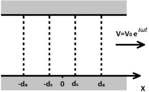
To compare the obtained results with the experimental data, the data in [14] was used. The experimental data presented there was obtained for the electrochemical cell made of platinum gauze electrodes separated by perforated dielectric spacers. In the experimental sample the thickness of the gauze electrode was 80 microns, while the thickness of the dielectric spacers was 130 microns. The correspondence of the parameters from the equations and the real experimental cell geometry obtained in this work is shown in Figure 2. Suppose that for a better correspondence between the real and the model geometries of the transformative system, infinitely thin planes corresponding to the electrodes in the theoretical model must be placed into the geometrical center of the experimental gauze electrodes. In that case dc 1.05*104m,
4 10 * 15 .
3
c
d m. Other data is taken the same as in [14]. Therefore, the following data is used in calculations: Ca 0.04mol/L, Cb 4mol/L,
9
10 * 2
3
I
D m2/sec, 2.4*109 K
I D
Figure 2. The correspondence between the experimental cell configuration tested in [14] and the parameters used in calculations. Namely, the planes presenting the electrodes in the model are placed in the center of real gauze electrodes. Here 1 are the anodes, 2 are the cathodes and 3 are the dielectric spacers.
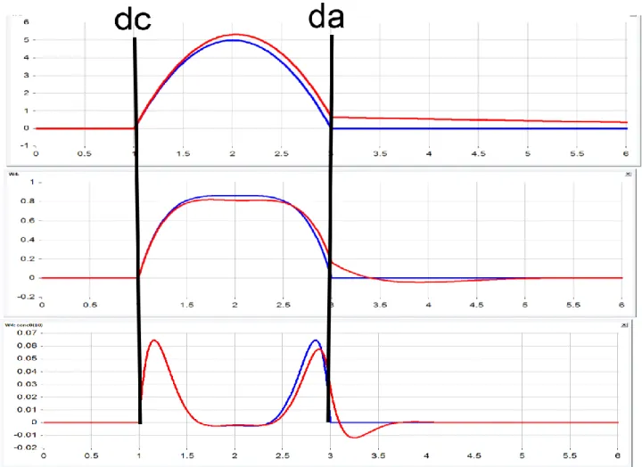
Figure 3 shows the distribution of non-dimensional concentration
) (
0 )
1 (
3 3
c a a I I
norm C V d d
D C
C
when hydrodynamic velocity achieves its maximum value. The horizontal axis presents a non-dimensional coordinates
c d
Figure 3. The distribution of a non-dimensional concentration when hydrodynamic velocity achieves its maximum value.
Legend:
Red curves – calculated according to (24) and (25),
Blue curves – solution with infinitely high conductivity w=0, Black lines show positions of the electrodes
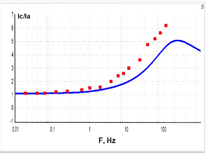
Figure 4. Ratio of the cathodic currents difference to the anodic currents difference. The red dots present the experimental data from [14] 1, the blue curve presents the calculations from the equation (27).
Legend:
Red squares – experimental data from [14] Blue curve – calculation according to (27).
It is notable that although this method is quite simple, the presented difference from the experimental data is even less than with the use of more complicated approach based on the system of Nernst-Planck equation solution (which admits only numeric solutions of the method) used in [14]. 4. CONCLUSIONS
The present work suggests a new approach to the theoretical model assembly for electrical currents in four-electrode electrochemical cell used as a sensitive element for motion parameters
1
Reprinted with minimal adaptation from Journal of Electroanalytical Chemistry, Vol. 661, Zhanyu Sun,V. Agafonov,E. Egorov, «The influence of the boundary condition on anodes for solution of convection– diffusion equation with the application to a four-electrode electrochemical cell», Pages 157-161, Figure 3,
sensors. The essence of the suggested approach is to use the equation of convective diffusion for
3
I active ions transfer together with the Laplace equation for electrical potential distribution (18). The basis for such approach is the condition standard for the studied system when the concentration of electrochemically active component in the solution is considerably less than the concentration of the base electrolyte. Herewith, as in the case of only the convective diffusion equation, I3ions migration
in electrical field may be not taken into account. At the same time, the change of the potential depending on the values of electrode currents and their spatial distribution is seen in the change of speed of reactions at the electrodes. The developed approach was tested at the example of one-dimension geometry of electrode system, similar to the classical Larkam model. The obtained results of the ratio of the anodic to the cathodic currents are in particularly good agreement with the experimental data.
The developed approach can be essentially used for more complex geometrical configurations of electrodes and is considerably more simple and less computer-demanding than the solution of the system of Nernst-Planck equations.
ACKNOWLEDGEMENTS.
The results presented in this paper have been obtained under the project supported by the Russian Ministry of Education and Science, the project ID is RFMEFI57514X0017. Authors sincerely thank colleagues from the Center for Molecular Electronics of MIPT for many fruitful discussion on the topics related to the publication.
References
1. V. Agafonov, A. Neeshpapa, and A. Shabalina, in Encyclopedia of Earthquake Engineering SE - 403-1, M. Beer, I. A. Kougioumtzoglou, E. Patelli, and I. S.-K. Au, Eds. Springer Berlin
Heidelberg, (2015), 1.
2. D. Chen, G. Li, J. Wang, J. Chen, W. He, Y. Fan, T. Deng, and P. Wang, Sensors Actuators, A: Physical, 202 (2013) 85.
3. H. Huang, V. Agafonov, and H. Yu, Sensors (Switzerland), 13 (2013) 4581.
4. A. Neeshpapa, A. Antonov, and V. Agafonov, Sensors (Switzerland), 15 (2014) 365.
5. H. Huang, B. Carande, R. Tang, J. Oiler, Z. Dmitriy, A. Vadim, and H. Yu, Proc. IEEE Int. Conf. Micro Electro Mech. Syst., (2013) 629.
6. N. Kapustian, G. Antonovskaya, V. Agafonov, K. Neumoin and M. Safonov, Geotechnical, Geological and Earthquake Engineering, 24 (2013) 353.
7. V. Agafonov, E. Egorov, and C. Rice, in 72nd European Association of Geoscientists and Engineers Conference and Exhibition 2010: A New Spring for Geoscience. Incorporating SPE EUROPEC 2010, 5 (2010) 3698.
8. V. Agafonov, E. Egorov, and D. Zaitsev, Gyroscopy Navig., 1 (2010) 246. 9. V. Kozlov and A. Kharlamov, Russ. J. Electrochem., 34 (1998) 174. 10.V. Agafonov and V. Krishtop, Russ. J. Electrochem., 40 (2004) 537. 11.V. Kozlov and D. Terent’ev, Russ. J. Electrochem., 38 (2002) 992. 12.V. Kozlov and D. Terent’ev, Russ. J. Electrochem., 39 (2003) 401.
16.Z. Sun and V. Agafonov, Electrochim. Acta, 55 (2010) 2036.
17.Z. Sun and V. Agafonov, Sensors Actuators, B: Chemical., 146 (2010) 231.
18.T. Deng, D. Chen, J. Wang, J. Chen, and W. He, Microelectromechanical Syst. J., 23 (2014) 92. 19.C. W. Larkam, J. Acoust. Soc. Am., 37 (1965) 664.
20.D. A. Bograchev and A. D. Davydov, Electrochim. Acta, vol. 47, no. 20, (2002), 3277. 21.V. M. Volgin and A. D. Davydov, Russ. J. Electrochem., vol. 48, no. 6, (2012), 565. 22.V. M. Agafonov and A. S. Nesterov, Russ. J. Electrochem., vol. 41, no. 8, (2005), 880.
![Figure 2. The correspondence between the experimental cell configuration tested in [14] and the parameters used in calculations](https://thumb-us.123doks.com/thumbv2/123dok_us/1829497.138871/11.893.127.741.100.584/figure-correspondence-experimental-cell-configuration-tested-parameters-calculations.webp)