Bangladesh University of Professionals (BUP)
Department of Information & Communication Technology
Experiment No: 01 (a)
Name of the experiment: Interfacing Arduino UNO with LED: LED Blinking
1.1
Objectives:
This example aims to familiarize the student with the basic operation of the Arduino Uno board, and Integrated Development Environment (IDE). By the end of the exercise, the student should be able to know the basic functionalities of the IDE.
1.2
Instruments/Materials Needed:
· 1 x Arduino Uno board and USB cable
· 1 x 5mm/3mm Red LED
· 1 x 470Ω resistor
· 1 x breadboard
1.3
Working Procedure:
[image:1.612.125.516.525.683.2]Proceed to the Arduino Folder and double-click the arduino application to open the Arduino IDE which is also shown below:
Computer Peripherals and Interfacing Lab MZI BUP
the examples folder of Arduino. To copy it, just navigate from arduino-00XX >
examples > Basics > Blink. See Appendix under Structure, Functions and Time or Section F for the functions' definitions
1 void setup(){
2 pinMode(13,OUTPUT);
}
3 void loop(){
4 digitalWrite(13,HIGH);
5 delay(1000);
6 digitalWrite(13,LOW);
7 delay(1000);
}
3. Press Ctrl + S or Icon on the IDE to save your sketch (the term for a source
code in Arduino).
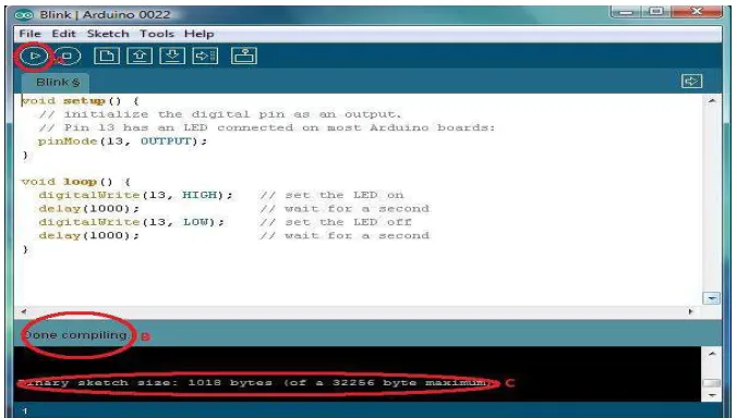
4. Click the Verify Button (A on fig. 14) to check if the sketch has no errors. At the
bottom of the screen you should see if the sketch was successfully scanned free of problems (B on fig. 14). Moreover, the size of the sketch file (C on fig. 14) is also indicated on the black screen at the bottom to shows that it fits the flash memory of the Arduino Uno.
[image:2.612.144.482.487.679.2]1.4 Test your Program
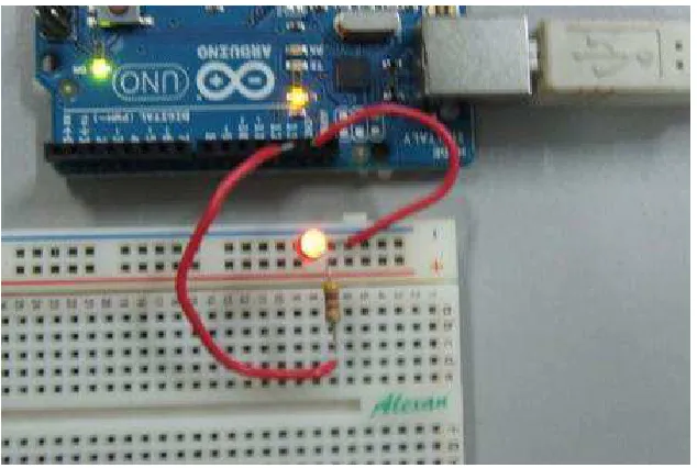
1. Connect an LED to a 470Ω resistor. Note: that the longer leg of the LED is the positive
(connected to one end of resistor and the shorter one is the negative (connected to the
ground). The other end of the resistor should then be connectedto the specified pin
[image:3.612.225.428.193.304.2]which is 13.
Figure 15: Schematic diagram of blink circuit.
2. Check if the board selected in the IDE is the one you are using, the Arduino Uno
board.
[image:3.612.103.512.386.658.2]Computer Peripherals and Interfacing Lab MZI BUP
IDE. To do this, connect the board to the computer then from the IDE front panel go to Tools > Serial Port (A on fig. 17). A list of COM’s should be there, choose the
COM number associated with the microcontroller board. Note: the microcontroller
board’s COM no. is found near the name of the device’s driver in Device Manager (B on
fig.17) [2].
Figure 17: Screenshot of both the Device Manager and Arduino IDE windows. Note that the COM number selected as Serial Port must be the same one found beside the device’s name
4. Finally, upload the sketch made earlier into the board by clicking the icon in the
IDE. The status of the upload can be found near the bottom of the program [2].
[image:4.612.118.526.152.454.2]5. If the Arduino Uno is connected to the PC or power source the LED should light up for 1 second and turn off for 1 second repeatedly.
Figure 19: Photo of the LED blinking. Note that the small LED on the board is also blinking because it is also connected to pin 13.
1.5 Code explanations:
Line Explanations
No.
1 Creates a function called setup. The function type is void and therefore
does not return any value after execution. This is only read once in a file execution and is required in a sketch.
2 The function pinMode() configures the specified pin which is 13 in this
sample. It sets digital pin 13 as output.
3 Creates a function called loop. The function type is also void and therefore
also does not return any value after execution. This is read repeatedly in a file execution and usually where the main program is. This is also
required in a sketch.
4 The digitalWrite() function writes a high(5V) or low(0V) on a specified
pin. In this case, a high state is written on pin 13 to light the LED.
5 The delay function needs a constant or variable of how long in millisecond
6
7 This line is the same as line 5 and prolongs the LED at OFF state for 1
second.
1.6 What to expect:
You have just written a sketch and programmed the Arduino Uno board to cause both the external LED and built-in LED connected to pin 13 to blink. You should see the LED blink when the board is connected to the PC by a USB cable or the board is connected to a DC supply.
1.7 Summary
APPENDIX
A. Arduino IDE Language Summary (taken fromhttp://arduino.cc/en/Reference/HomePage)
Structure
• setup() – is called once when a sketch starts. Used to initialize variables, pin modes, start using libraries, etc.
• loop() - as its name implies, this function loops consecutively the code inside it to allow your program to respond and change.
Variables
Constants
• HIGH | LOW – when a pin is in INPUT mode, the microcontroller reports HIGH as a voltage of 3V or more and LOW if it is 2V or less. Also, the user can write HIGH while the pin is in INPUT mode and this will set the internal 20K pull-up resistor which will steer the pin to HIGH reading unless pulled LOW by external circuitry. When a pin is in OUTPUT mode, HIGH sets the pin to 5V and LOW sets it to 0V.
• INPUT | OUTPUT – configures the pins to take in input from a circuit or provide output to a circuit respectively.
Functions
Digital I/O
• pinMode(pin, mode) – configures the pin to behave as either an input or an output
o pin – refers to the number of pin to be configured.
o Mode – refers to what mode the pin is to be set (INPUT or OUTPUT).
• digitalWrite(pin, value) – writes a high (5V) or low (0V) value to a digital pin.
o value – HIGH or LOW
• digitalRead(pin) – reads the value from a specified digital pin if it is high or low.
Analog I/O
• analogReference(type) – configures the reference voltage used for analog input. o type – can be any of the ones below:
DEFAULT – the default analog reference of 5V or 3.3V depending on board. INTERNAL – uses the built-in reference available to some microcontrollers.
• INTERNAL1V1 – uses built-in 1.1V reference (Arduino Mega only)
8
• analogWrite(pin, value) – writes an analog value (PWM wave) to a pin.
o value – the duty cycle and is between 0 (always off) and 255 (always on).
Time
• millis() – returns the number of milliseconds since the Arduino board began running the current program.
• micros() – returns the number of microseconds since the Arduino board began running the current program.
• delay(ms) – pauses the program for the amount of time specified as parameter.
o ms – the number of milliseconds to pause.


![fig. 17) [2].](https://thumb-us.123doks.com/thumbv2/123dok_us/8353102.311400/4.612.118.526.152.454/fig.webp)