Daniel Ritter, Norman May
SAP SE
Walldorf (Baden), Germany {firstname.lastname}@sap.com
Fredrik Nordvall Forsberg
University of Strathclyde Glasgow, Scotland
Stefanie Rinderle-Ma
University of Vienna Vienna, Austria
ABSTRACT
Enterprise Application Integration is the centerpiece of current on-premise, cloud and device integration scenarios. We describe optimization strategies that help reduce the model complexity, and improve the process execution using design time techniques. In order to achieve this, we formalize compositions of Enterprise Integration Patterns based on their characteristics, and propose a realization of optimization strategies using graph rewriting. The framework is successfully evaluated on a real-world catalog of pattern compositions, containing over 900 integration scenarios.
CCS CONCEPTS
•Applied computing→Enterprise application integration; •Information systems→Data exchange;
KEYWORDS
Enterprise Application Integration, Enterprise Integration Patterns, Optimization Strategies.
ACM Reference Format:
Daniel Ritter, Norman May, Fredrik Nordvall Forsberg, and Stefanie Rinderle-Ma. 2018. Optimization Strategies for Integration Pattern Compositions. In
DEBS ’18: The 12th ACM International Conference on Distributed and Event-based Systems, June 25–29, 2018, Hamilton, New Zealand.ACM, New York, NY, USA, 12 pages. https://doi.org/10.1145/3210284.3210295
1
INTRODUCTION
Enterprise Application Integration (EAI) is the centerpiece of cur-rent IT infrastructure and integration scenarios, and essentially amounts to composing Enterprise Integration Patterns (EIPs) from a catalog comprising the original patterns [23] and recent addi-tions [37, 40]. This can result in complex models that are often vendor-specific, informal and ad-hoc [37]; optimizing such integra-tion processes is desirable, but hard. In most cases this is further complicated by data aspects being absent in the model. As a con-crete motivation for a formal framework for data-aware integration process optimization, consider the following example: many or-ganizations have started to connect their on-premise applications such as Customer Relationship Management (CRM) systems with cloud applications such as SAP Cloud for Customer (COD) using
Permission to make digital or hard copies of all or part of this work for personal or classroom use is granted without fee provided that copies are not made or distributed for profit or commercial advantage and that copies bear this notice and the full citation on the first page. Copyrights for components of this work owned by others than ACM must be honored. Abstracting with credit is permitted. To copy otherwise, or republish, to post on servers or to redistribute to lists, requires prior specific permission and/or a fee. Request permissions from [email protected].
[image:1.612.325.553.177.248.2]DEBS ’18, June 25–29, 2018, Hamilton, New Zealand © 2018 Association for Computing Machinery. ACM ISBN 978-1-4503-5782-1/18/06. . . $15.00 https://doi.org/10.1145/3210284.3210295
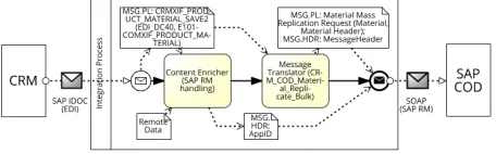
Figure 1: SAP Hybris Cloud Replicate Material from SAP Business Suite (a “hybrid integration” scenario).
integration processes similar to the one shown in Fig. 1. ACRM Materialis sent from the CRM system via EDI (more precisely SAP IDOC transport protocol) to an integration process running on SAP Cloud Platform Integration (SAP CPI)1. The integration process enriches the message header (MSG.HDR) with additional infor-mation based on a document number for reliable messaging (i.e., AppID), which allows redelivery of the message in an exactly-once service quality [40]. The IDOC structure is then mapped to the COD service description and sent to the COD receiver. Already in this simple scenario an obvious improvement can be applied: the data-independent Content Enricher and Message Translator patterns [23] could be executed in parallel. This insight would per-haps not be obvious without the data flow in the model, and leads to questions such as the following:“are there other optimizations that could also be applied, and how can the modeling be supported by this?”. Currently these questions cannot be answered, since ap-proaches for verification and static analysis of “realistic data-aware” business and integration processes are missing, as recent surveys on event data [1, 16], workflow management [27], and in particular application integration [37] report. Hence, this work aims to fill this gap, based on the following research questions:
RQ1 What are relevant optimization techniques for EAI pattern compositions?
RQ2 How can pattern compositions be suitably formalized for optimizations?
RQ3 How can optimization strategies be formally defined? In this work, we develop a verification and static analysis frame-work for applying and reasoning about optimizations of data-aware integration patterns. Our main contribution is a graph-based rep-resentation of integration patterns, so that optimizations can be realized as graph rewriting rules. To show the feasibility of our framework, we analyzed its use on a catalog of over 900 real-world
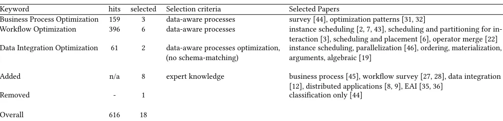
Table 1: Optimizations in related domains — horizontal search
Keyword hits selected Selection criteria Selected Papers
Business Process Optimization 159 3 data-aware processes survey [44], optimization patterns [31, 32]
Workflow Optimization 396 6 data-aware processes instance scheduling [2, 7, 43], scheduling and partitioning for in-teraction [3], scheduling and placement [6], operator merge [22] Data Integration Optimization 61 2 data-aware processes optimization,
(no schema-matching)
instance scheduling, parallelization [46], ordering, materialization, arguments, algebraic [19]
Added n/a 8 expert knowledge business process [45], workflow survey [27, 28], data integration [12], distributed applications [8, 9], EAI [35, 36]
Removed - 1 classification only [44]
Overall 616 18
integration scenarios. With our approach, we can show that 81% of the original scenarios from 2015 and still up to 52% of the cur-rent SAP CPI content from 2017 could be improved through a parallelization of scenario parts. We stress that we use the word “optimization” here in the sense of, e.g., an optimizing compiler: a process which iteratively improves compositions, but gives no guar-antee of optimality. Due to brevity, we focus on the common EAI optimization objectives [23]: message throughput (on experimental runtime benchmarks), pattern processing latency (on an abstract cost model), and also runtime independent model complexity [42] from the process modeling domain. Furthermore, we concentrate on pattern compositions within one integration process (not to or within message endpoints).
Methodology.Overall, we follow the design science research ap-proach from Peffers et al. [33] to systematically analyze the state-of-the-art. At first, we collect optimization techniques as optimization strategies from related domains (answering RQ1) by conducting a horizontal literature search based on Kitchenham [26]. We opt for a high-level representation of pattern compositions as control flow graphs [4] (where the nodes represent extended EIPs) with commu-nication contracts. This allows our representation to specify data and throughput aspects — which BPMN-based models cannot [40] — whilst still modeling the composition logic of the patterns, rather than their internal logic as in Petri Net-based models [17] (answer-ing RQ2). We then formalize the optimization strategies based on the contract graphs using graph rewriting techniques (answering RQ3), and evaluate them on real-world pattern compositions.
Outline.In Sect. 2, we collect optimization techniques, identify requirements for optimizing EIP compositions, and classify the optimization strategies and optimization objectives (i.e., modeling complexity, processing latency, message throughput). Our formal model of pattern compositions is introduced in Sect. 3. Optimization strategies are then formalized in Sect. 4, and evaluated on case studies based on the objectives in Sect. 5. We discuss related work in Sect. 6 and conclude in Sect. 7.
2
STATIC OPTIMIZATION STRATEGIES
In this section we survey recent attempts to optimize composed EIPs, in order to motivate the need to formalize their semantics. As a result, we derive three so far unexplored prerequisitesR1–R3for optimizing compositions of EIPs.
2.1
Identifying optimization strategies
Since a formalization of the EAI foundations in the form of inte-gration patterns for static optimization of “data-aware” pattern processing is missing [37], we conducted a horizontal literature search [26] to identify optimization techniques in related domains. For EAI, the domains of business processes, workflow management and data integration are of particular interest. The results of our analysis are summarized in Tab. 1. Out of the resulting 616 hits, we selected 18 papers according to the search criteria “data-aware processes”, and excluded work on unrelated aspects. Table 2 lists the optimization techniques, already mapped to EAI, and skipping those techniques that do not provide solutions for our optimization ob-jectives or within an integration process. This resulted in theseven
papers cited in the table. The mapping of techniques from related domains to EAI was done by for instance taking the idea of pro-jection push-downs [11, 19, 22, 31, 45] and deriving the early-filter or early-mapping technique in EAI. We categorized the techniques according to their impact (e.g., structural or process, data-flow) in context of the objectives for which they provide solutions.
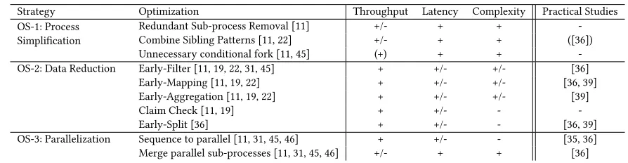
In the following subsections, we now briefly discuss the opti-mization strategies listed in Tab. 2, in order to derive prerequisites needed for optimizing compositions of EIPs. To relate to their prac-tical relevance and coverage so far (in the form of evaluations on “real-world” integration scenarios), we also discuss existing “data-aware” message processing solutions for each group of strategies.
2.2
Process Simplification
Table 2: Optimization Strategies in context of the objectives
Strategy Optimization Throughput Latency Complexity Practical Studies OS-1: Process
Simplification
Redundant Sub-process Removal [11] +/- + + -Combine Sibling Patterns [11, 22] +/- + + ([36]) Unnecessary conditional fork [11, 45] (+) + + -OS-2: Data Reduction Early-Filter [11, 19, 22, 31, 45] + +/- +/- [36]
Early-Mapping [11, 19, 22] + +/- +/- [36, 39] Early-Aggregation [11, 19, 22] + +/- +/- [39]
Claim Check [11, 19] + +/- -
-Early-Split [36] + +/- - [36, 39]
OS-3: Parallelization Sequence to parallel [11, 31, 45, 46] + +/- - [35, 36] Merge parallel sub-processes [11, 31, 45, 46] +/- + + [36] + = improvement, - = deterioration, +/- = no effect, (+) = slight improvement, (-) = slight deterioration.
evolutionary search approaches on workflow graphs, and Vrhovnik et al. [45], who use a rule formalization on query graphs.
2.3
Data Reduction
The reduction of data can be facilitated by pattern push-down opti-mizations of message-element-cardinality-reducing patterns, which we callEarly-Filter(for data; e.g., remove elements from the message content),Early-Mapping(e.g., apply message transformations), as well as message-reducing optimization patterns likeEarly-Filter(for messages; e.g., remove messages),Early-Aggregation(e.g., combine multiple messages to fewer ones),Early-Claim Check(e.g., store content and claim later without passing it through the pipeline), and
Early-Split(e.g., cut one large message into several smaller ones). Measuring data reduction requires a cost model based on the charac-teristics of the patterns, as well as the data and element cardinalities. For example, the practical realizations for multimedia [39] and hard-ware streaming [36] show improvements especially for early-filter, split and aggregation, as well as moderate improvements for early-mapping. This requires a formalization that is able to represent data or element flow (R2). Data reduction optimizations target message throughput improvements (i.e., processed messages per time unit), however, some have a negative impact on the model complexity. Previous work on data reduction include Getta [19], who targets optimization techniques on relational algebra expres-sions, and Niedermann, Radeschütz and Mitschang [31], who define optimizations algorithmically for a graph-based model.
2.4
Parallelization
Parallelization of processes can be facilitated through transforma-tions such asSequence to Parallel(e.g., duplicate pattern or sequence of pattern processing), or, if not beneficial, reverted, e.g., byMerge Parallel. For example, good practical results have been shown for vectorization [35] and hardware parallelization [36]. Therefore, again, acontrol graph structure (R1)is required. Although the main focus of parallelization is message throughput, heterogeneous variants also improve latency. In both cases, parallelization requires additional patterns, which negatively impacts the model complexity. The opposite optimization of merging parallel processes mainly improves the model complexity and latency. Previous work on pat-tern parallelization include Zhang et al. [46], who defines a service composition model, to which algorithmically defined optimizations are applied.
2.5
Discussion
Due to our objectives and our focus on optimizations within a process, the collection of optimizations in Tab. 2 is not complete. For instance, we have not treated pattern placement optimizations (pushing patterns to message endpoints, i.e., sender and receiver applications), or optimizations that reduce interaction (helping to stabilize the process). Besides control flow (as used in most of the related domains), a suitable formalization must be able to represent thecontrol graph structure (R1)(including reachability and con-nectedness properties) and thedata element flow (R2)between patterns (not within a pattern). Furthermore, the formalization must allow verification ofcorrectness (R3)on a pattern-compositional level (i.e., each optimization produces a correct pattern composi-tion), taking the inter-pattern data exchange semantics into account. In contrast to the related work, we define a novel data-aspect rep-resentation of the extended EIPs and guarantee correctness.
3
GRAPH-BASED PATTERN COMPOSITIONS
In this section, we introduce our formalization of pattern composi-tions, and an abstract cost model for them. Such a formalization is needed in order to talk about optimizations rigorously.
3.1
Integration Pattern Graphs
Summarizing the requirementsR1–R3collected in the previous section, a suitable formalization of integration patterns is graph-based, can represent thedata element flow, and allowscorrectness checking. Hence, we define an Integration Pattern Typed Graph (IPTG) as an extended control flow graph [4] as follows. Let us first fix some notation: a directed graph is given by a set of nodesP and a set of edgesE ⊆P×P. For a nodep ∈ P, we write•p=
{p′∈P| (p′,p) ∈E} for the set of direct predecessors ofp, andp•=
{p′′∈P| (p,p′′) ∈E} for the set of direct successors ofp.
Definition 3.1. Anintegration pattern typed graph (IPTG)is a directed graph with set of nodesP and set of edgesE ⊆ P×P, together with a functiontype : P →T, whereT = {start, end, message processor, fork, structural join, condition, merge, external call}. An IPTG(P,E,type)iscorrectif
• ∃p1,p2∈P withtype(p1)= start andtype(p2)= end; • iftype(p) ∈{fork, condition} then| •p|=1 and|p• | =n,
and iftype(p)=jointhen| •p|=nand|p• |=1;
•iftype(p) ∈{external call} then| •p|=1 and|p• |=2; •The graph(P,E)is connected and acyclic.
In the definition, we think ofPas a set of extended EIPs that are connected by message channels inE, as in a pipes and filter archi-tecture. The functiontyperecords what type of pattern each node represents. The first correctness condition says that an integration pattern has at least one source and one target, while the next three states the cardinality of the involved patterns coincide with the in- and out-degrees of the nodes in the graph representing them. The last condition states that the graph represents one integration pattern, not multiple unrelated ones, and that messages do not loop back to previous patterns.
To represent the data flow, i.e., the basis for the optimizations, the control flow has to be enhanced with (a) the data that is processed by each pattern, and (b) the data exchanged between the patterns in the composition. The data processed by each pattern (a) is described as a set ofpattern characteristics, formally defined as follows:
Definition 3.2. Apattern characteristicassignment for an IPTG (P,E,type)is a functionchar:P→2PC, assigning to each pattern a subset of the set
PC=({MC} ×N×N) ∪
({ACC} × {ro,rw}) ∪
({MG} ×B) ∪
({CND} ×2BExp) ,
whereBis the set of Booleans,BExpthe set of Boolean expressions, and MC, CHG, MG, CND some distinct symbols.
The property and value domains in the definition are based on the pattern descriptions in [23, 37], and could be extended if further analysis required it. We briefly explain the intuition behind the characteristics: the characteristic(MC,n,k)represents a message cardinality ofn:k,(ACC,x)the message access, depending on if xis read-only ro or read-write rw, and the characteristic(MG,y) represents whether the pattern is message generating depending on the Booleany. Finally(CND,X)represents the conditions for the pattern collected in the set of Boolean expressionsX.
Example 3.3. The characteristics of a content-based routerCBR ischar(CBR)={(MC, 1:1), (ACC, ro), (MG, false), (CND,{cnd1, . . . , cndn−1})}, because of the workflow of the router: it receives exactly
one message, then evaluates up ton−1 routing conditionscnd1up to cndn−1(one for each outgoing channel), until a condition matches. The original message is then rerouted read-only (in other words, the router is not message generating) on the selected output channel, or forwarded to the default channel, if no condition matches.
The data exchange between the patterns (b) is based oninput and output contracts(similar to data parallelization contracts in [5]). These contracts specify how the data is exchanged in terms of required message properties of a pattern during the data exchange, formally defined as follows:
Definition 3.4. Apattern contractassignment for an IPTG(P,E,type) is a functioncontr:P →2CPT×2EL, assigning to each pattern a subset of the set
CPT={signed,encrypted,encoded} × {yes,no,any}
and a subset of the set
EL=MS×2D
whereMS={HDR,PL,ATTCH}, andDis a set of data elements (the concrete elements ofDare not important, and will vary with the application domain).
Each pattern will have an inbound and an outbound pattern contract, describing the format of the data it is able to receive and send respectively — the role of pattern contracts is to make sure that adjacent inbound and outbound contracts match. The setCPT
in a contract represents integration concepts, while the setEL rep-resents data elements and the structure of the message: its headers (HDR,H), its payload(PL,Y)and its attachments(ATTCH,A).
Example 3.5. A content-based router is not able to process en-crypted messages. Recall that its pattern characteristics included a collection of routing conditions: these might require read-only access to message elements such as certain headersh1or payload elementse1,e2. Hence the input contract for a router mentioning these message elements is
inContr(CBR)=({(encrypted,no)},{(HDR,{h1}),(PL,{e1,e2})}) .
Since the router forwards the original message, the output contract is the same as the input contract.
Definition 3.6. Let(C,E) ∈ 2CPT ×2ELbe a pattern contract, andX ⊆ 2CPT ×2EL a set of pattern contracts. WriteXCPT =
{C′| (∃E′) (C′,E′) ∈ X}andXEL = {E′ | (∃C′) (C′,E′) ∈ X}. We say that(C,E)matchesX, in symbolsmatch((C,E),X), if the following condition holds:
(∀(p,x) ∈C)x=any∨ (∀C′∈XCPT)(∃(p′,y) ∈C′)
p=p′∧ (y=
any∨y=x) ∧
(∀(m,Z) ∈E)Z ⊆ Ø
(m,Z′)∈∪X EL
Z′
We are interested in an inbound contractKinmatching the out-bound contractsK1, . . . ,Knof its predecessors. In words, this is the case if (i) for all integration concepts that are important toKin, all contractsKi either agree, or at least one ofKinorKi accepts any value; and (ii) together,K1, . . . ,Knsupply all the message elements thatKinneeds.
Since pattern contracts can refer to arbitrary message elements, a formalization of an integration pattern can be quite precise. On the other hand, unless care is taken, the formalization can easily become specific to a particular pattern composition. In practice, it is often possible to restrict attention to a small number of impor-tant message elements (see Example 3.8 below), which makes the formalization manageable.
Putting everything together, we formalize pattern compositions as integration pattern typed graphs with pattern characteristics and inbound and outbound pattern contracts for each pattern:
Definition 3.7. Anintegration pattern contract graph(IPCG) is a tuple
(P,E,type,char,inContr,outContr)
pattern contract assignments, called the inbound and outbound con-tract assignment respectively. It iscorrect, if the underlying IPTG (P,E,type)is correct, and inbound contracts matches the outbound contracts of the patterns’ predecessors, i.e.
(∀p) p=start∨match(inContr(p),{outContr(p′) |p′∈ •p}) .
Two IPCGs areisomorphicif there is a bijective function be-tween their patterns that preserves edges, types, characteristics and contracts.
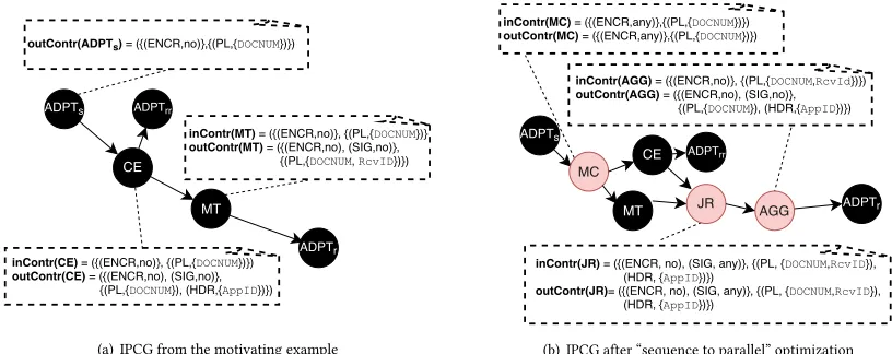
Example 3.8. Figures 2(a) and 2(b) show IPCGs representing an excerpt of the motivating example from the introduction. Figure 2(a) represents the IPCG of the original scenario with a focus on the contracts, and Fig. 2(b) denotes an already improved composition showing the characteristics and giving an indication on the pattern latency. In Fig. 2(a), the input contractinContr(CE)of the content enricher patternCErequires a non-encrypted message and a pay-load elementDOCNUM. The content enricher makes a query to get an application IDAppIDfrom an external system, and appends it to the message header. Hence the output contractoutContr(CE)contains
(HDR,{AppID}). The content enricher then emits a message that
is not encrypted or signed. A subsequent message translatorMT requires the same message payload, but does not care about the appended header. It adds another payloadRcvIDto the message. Comparing inbound and outbound pattern contracts for adjacent patterns, we see that this is a correct IPCG.
One improvement of this composition is depicted in Fig. 2(b), where the independent patternsCEandMT have been parallelized. To achieve this, a read-only structural fork with channel cardinality 1:nin the form of a multicastMChas been added. The inbound and outbound contracts ofMCare adapted to fit into the composition. After the concurrent execution ofCE andMT, a join router JR brings the messages back together again and feeds the result into an aggregatorAGGthat restores the format thatADPTr expects. We see that the resulting IPCG is still correct, so this would be a sound optimization.
3.2
Abstract Cost Model
In order to decide if an optimization is an improvement or not, we want to associate abstract costs to integration patterns. We do this on the pattern level, similar to the work on data integration operators [10]. The cost of the overall integration pattern can then be computed as the sum of the cost of its constituent patterns. Costs are considered parameterized by the cardinality of data inputs|dini|
(1 ≤ i ≤ n, if the pattern has in-degreen), data outputs |doutj|
(1≤j ≤m, if the pattern has out-degreem), and external resource
data sets|dr|. The costs can also refer to the pattern characteristics.
Definition 3.9. Acost assignmentfor an IPCG(P,E,type,char, inContr,outContr)is an functioncost(p):Nn×Nk×Nr →Qfor
eachp∈P, wherephas in-degreen, out-degreekandrexternal
connections. The costcost(G):NN×NK×NR→Qof an IPCG pattern graphG = (P,E,type,pc,ic,oc)with a cost assignment, whereNis the sum of the in-degrees of its patterns,Kthe sum of their out-degrees, andRthe sum of their external connections, is defined to be the sum of the costs of its constituent patterns:
cost(G)(din,dout,dr)=Õ
p∈P
[image:5.612.316.557.101.286.2]cost(p)(|din(p)|,|dout(p)|,|dr(p)|)
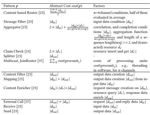
Table 3: Abstract costs of relevant patterns
Patternp Abstract Costcost(p) Factors
Content-based Router [23]
Ín−1
i=0|din,i|
2 n=#channel conditions, half of them
evaluated in average
Message Filter [23] |din| input data condition|din|
Aggregator [23] 2× |din|+avд|d(inl en|+|d(seqr| )) correlation, and completion condi-tions |din|, aggregation function
|din|+|dr|
avд(l en(seq))and length of a se-quence length(seq)>=2, and (trans-acted) resourcedr
Claim Check [23] 2× |dr| resource insert and get|dr|
Splitter [23] |dout|
-Multicast, JoinRouter [37] Ín
i=0cost(procuniti) costs of processing units cost(procuniti), e.g., threading in software, fornchannels
Content Filter [23] |dout| output data creation|dout|
Mapping [23] |din|+|dout| output data creation|dout|from in-put data|din|
Content Enricher [23] |din|+|dr|+|dout| request message creation on|din|, resource query|dr|, response data enrich|dout|
External Call [37] |dout|+|din| request|dout|and reply data|din|
Receive [23] |din| input data|din|
Send [23] |dout| output data|dout|
where we suggestively have written|din(p)|for the projection from the tupledincorresponding top, similarly for|dout(p)|and|dr(p)|.
We have defined the abstract costs of the patterns discussed in this work in Tab. 3 — these will be used in the evaluation in Sect. 5. We now explain the reasoning behind them. Routing patterns such as content based routers, message filters and aggregators mostly operate on the input message, and thus have an abstract cost related to its element cardinality|din|. For example, the abstract cost of the content-based router iscost(CBR)=
Ín−1 i=0 |din,i|
2 , since it evaluates on average n−21 routing conditions on the input message. More complex routing patterns such as aggregators evaluate correlation and completion conditions, as well as an aggregation function on the input message, and also on sequences of messages of a certain length from an external resource. Hence the cost of an aggrega-tor iscost(AGG)=2× |din|+ |din|+|dr|
avд(len(seq)). In contrast, message
transformation patterns like content filters and enrichers mainly construct an output message, hence their costs are determined by the output cardinality|dout|. For example, content enrichers create a request message from the input message with cost|din|, conducts an optional resource query|dr|, and creates and enriches the response with cost|dout|. Finally, the cost of message creation patterns such as external calls, receivers, and senders arise from costs for transport, protocol handling, and format conversion, as well as decompression. Hence the cost depends on the element cardinalities of input and output messages|din|,|dout|.
Example 3.10. We return to the claimed improved composition in Example 3.8. The latency of the compositionG1in Fig. 2(a), calcu-lated from the constituent pattern latencies, iscost(G1)=tCE+tMT. The latency improvement potential given by switching to the com-positionG2in Fig. 2(b) is given bycost(G2) =max(tCE,tMT)+ tMC +tJ R +tAGG. Obviously it is only beneficial to switch if
(a) IPCG from the motivating example (b) IPCG after “sequence to parallel” optimization
Figure 2: An IPCG of an excerpt of the motivating example.
4
OPTIMIZATION STRATEGY REALIZATION
In this section we formally define the optimizations from the dif-ferent strategies identified in Tab. 2 in the form of a rule-based graph rewriting system. This gives a formal framework in which different optimizations can be compared. We begin by describing the graph rewriting framework, and subsequently apply it to define the optimizations.
4.1
Graph Rewriting
Graph rewriting provides a visual framework for transforming graphs in a rule-based fashion. A graph rewriting rule is given by two embeddings of graphsL←-K,→R, whereLrepresents the left hand side of the rewrite rule,Rthe right hand side, andKtheir intersection (the parts of the graph that should be preserved by the rule). A rewrite rule can be applied to a graphGafter a match ofLinGhas been given as an embeddingL,→G; this replaces the match ofLinGbyR. The application of a rule is potentially non-deterministic: several distinct matches can be possible [14]. Visually, we represent a rewrite rule by a left hand side and a right hand side graph colored green and red: green parts are shared and representK, while the red parts are to be deleted in the left hand side, and inserted in the right hand side respectively. For instance, the following rewrite rule moves the nodeP1past a fork by making a copy in each branch, changing its label fromctoc′in the process:
Formally, the rewritten graph is constructed using a double-pushout (DPO) [15] from category theory. We use DPO rewriting since rule applications are side-effect free (e.g., no “dangling” edges) and local (i.e., all graph changes are described by the rules). We additionally use Habel and Plump’s relabeling DPO extension [21] to facilitate the relabeling of nodes in partially labeled graphs. In Fig. 2, we showed contracts and characteristics in dashed boxes, but in the rules that follow, we will represent them as (schematic) labels inside the nodes for space reasons.
In addition, we also consider rewrite rules parameterized by graphs, where we draw the parameter graph as a cloud (see e.g., Fig. 3(a) for an example). A cloud represents any graph, sometimes with some side-conditions that are stated together with the rule. When looking for a match in a given graphG, it is of course suffi-cient to instantiate clouds with subgraphs ofG— this way, we can reduce the infinite number of rules that a parameterized rewrite rule represents to a finite number. Parameterized rewrite rules can formally be represented using substitution of hypergraphs [34] or by !-boxes in open graphs [25]. Since we describe optimization strategies as graph rewrite rules, we can be flexible with when and in what order we apply the strategies. We apply the rules repeat-edly until a fixed point is reached, i.e., when no further changes are possible, making the process idempotent. Each rule application preserves IPCG correctness in the sense of Definition 3.7, because input contracts do not get more specific, and output contracts re-main the same. Methodologically, the rules are specified by pre-conditions, change primitives, post-conditions and an optimization effect, where the pre- and post-conditions are implicit in the appli-cability and result of the rewriting rule.
4.2
OS-1: Process Simplification
We first consider the process simplification strategies from Sect. 2 OS-1 to OS-3 that mainly strive to reduce the model complexity and latency.
4.2.1 Redundant sub-process.This optimization removes redun-dant copies of the same sub-process within a process.
[image:6.612.319.556.610.677.2]Change primitives:The rewriting is given by the rule in Fig. 3(a), whereSG1 andSG2 are isomorphic pattern graphs with in-degree nand out-degreem. In the right hand side of the rule, theCEnodes add the context of the predecessor node to the message in the form of a content enricher pattern, and theCBRnodes are content-based routers that route the message to the correct recipient based on the context introduced byCE. The graphSG1′is the same asSG1, but with the context introduced byCEcopied along everywhere. Effect:The optimization is beneficial for model complexity when the isomorphic subgraphs contain more thann+mnodes, wheren is the in-degree andmthe out-degree of the isomorphic subgraphs. The latency reduction is by the factor of subgraphs minus the latency introduced by thenextra nodesCEandmextra nodesCBR.
4.2.2 Combine sibling patterns.Sibling patterns have the same parent node in the pattern graph (e.g., they follow a non-conditional forking pattern) with channel cardinality of 1:1. Combining them means that only one copy of a message is traveling through the graph instead of two — for this transformation to be correct in general, the siblings also need to be side-effect free, i.e., no external calls, although this is not captured by our correctness criteria. Change primitives:The rule is given in Fig. 3(b), whereSG1and SG2are isomorphic pattern graphs, andFis a fork.
Effect:The model complexity and latency are reduced by the model complexity and latency ofSG2.
4.3
OS-2: Data Reduction
Now, we consider data reduction optimization strategies, which mainly target improvements of the message throughput (incl. reduc-ing element cardinalities). These optimizations require that pattern input and output contracts are regularly updated with snapshots of element data setsELinandELoutfrom live systems (cf. Sect. 3), e.g., from experimental measurements through benchmarks [38].
4.3.1 Early-Filter.A filter pattern can be moved to or inserted prior to some of its successors to reduce the data to be processed. The following types of filters have to be differentiated:
•Amessage filterremoves messages with invalid or incom-plete content. It can be used to prevent exceptional situations, and thus improves stability.
•Acontent filterremoves elements from messages, thus re-duces the amount of data passed to subsequent patterns.
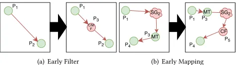
[image:7.612.320.555.425.490.2](a) Early Filter (b) Early Mapping Figure 4: Rules for early-filter and early-mapping.
Change primitives:The rule is given in Fig. 4(a), whereP3 is either a content or message filter matching the output contracts of P1and the input contract ofP2, removing the data not used byP2.
Effect:The message throughput increases by the ratio of the num-ber of reduced data elements that are processed per second, unless limited by the throughput of the additional pattern.
4.3.2 Early-Mapping.A mapping that reduces the number of elements in a message can increase the message throughput. Change primitives:The rule is given in Fig. 4(b), whereP3is an element reducing message mapping compatible with bothSG2,P4,
andP1,SG2, and whereP4does not modify the elements mentioned
in the output contract ofP3. FurthermoreP5 is a content filter, which ensures that the input contract ofP4is satisfied.
Effect:The message throughput for the subgraph subsequent to the mapping increases by the ratio of the number of unnecessary data elements processed.
4.4
OS-3: Parallelization
Parallelization optimization strategies increase message through-put. Again, these optimizations require experimentally measured message throughput statistics, e.g., from benchmarks [38].
4.4.1 Sequence to parallel.A bottleneck sub-sequence with chan-nel cardinality 1:1 can also be handled by distributing its input and replicating its logic. The parallelization factor is the average mes-sage throughput of the predecessor and successor of the sequence divided by two, which denotes the improvement potential of the bottleneck sub-sequence. The goal is to not overachieve the mean of predecessor and successor throughput with the improvement to avoid iterative re-optimization. Hence the optimization is only executed, if the parallel sub-sequence reaches lower throughput than their minimum.
[image:7.612.54.292.572.638.2](a) Sequence to parallel (b) Heterogeneous sequence to parallel Figure 5: Rules for sequence to parallel variants.
Change primitives:The rule is given in Fig. 5(a), whereSSQ1is a bottleneck sub-sequence,P2a fork node,P3a join router, and each
SSQ′
kis a copy ofSSQ1, for 1≤k≤n. The parallelization factorn
is a parameter of the rule.
Effect:The message throughput improvement rate depends on the parallelization factorn, and the message throughput of the balancing fork and join router on the runtime. For a measured throughputtof the bottleneck sub-sequences, the throughput can be improved ton×t≤average of the sums of the predecessor and successor throughput, while limited by the upper boundary of the balancing fork or join router.
Figure 6: Pattern composition evaluation pipeline.
combined outbound contracts ofPi andPjfulfill the input contract of the successor pattern ofPj.
Change primitives:The rule is given in Fig. 5(b), where the se-quential sub-sequence partsSSQ1, ..,SSQncan be parallelized,P3is a parallel fork,P4is a join router, andP5is an aggregator that waits for messages from all sub-sequence part branches before emitting a combined message that fulfills the input contract ofP2. Effect:Synchronization latency can be improved, but the model complexity increases by 3. The latency improves from the sum of the sequential pattern latencies to the maximal latency of all sub-sequence parts plus the fork, join, and aggregator latencies.
5
EVALUATION
In this section, we apply the optimizations to integration processes from a commercial cloud integration system in a quantitative anal-ysis, and exemplify the results by two real-world case studies.
5.1
Quantitative Analysis
We applied the optimization strategies OS-1–3 to 627 integration scenarios from the 2017 standard content of the SAP CPI (called ds17 below), and compared with 275 scenarios from 2015 (called ds15). Our goal is to show the applicability of our approach to real-world integration scenarios, as well as the scope and trade-offs of the optimization strategies. The comparison with a previous content version features a practical study on content evolution. To analyze the difference between different scenario domains, we grouped the scenarios into the following categories [37]: On-Premise to Cloud (OP2C), Cloud to Cloud (C2C), and Business to Business (B2B). Since hybrid integration scenarios such as OP2C target the extension or synchronization of business data objects, they are usually less complex. In contrast native cloud application scenarios such as C2C or B2B mediate between several endpoints, and thus involve more complex integration logic [37]. The process catalog also contained a small number of simple Device to Cloud scenarios; none of them could be improved by our approach.
Setup: Construction and analysis of IPCGsFor the analysis, we constructed an IPCG for each integration scenario following the workflow sketched in Fig. 6. The integration scenarios are stored as process models in a BPMN-like notation [40] (similar to Fig. 1).
0 1 2 3 4 5 6 7 8 9
all op2c c2c b2b misc.
Average number of patterns per scenario
[image:8.612.330.539.88.214.2]ds15 ds17
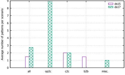
Figure 7: Pattern reduction per scenario.
The process models reference data specifications such as schemas (e.g., XSD, WSDL), mapping programs, selectors (e.g., XPath) and configuration files. For every pattern used in the process mod-els, runtime statistics are available from benchmarks [38]. The data specifications are picked up from the 2015 content archive and from the current 2017 content catalog, while the runtime benchmarks are collected using the open-source integration systemApache Camel[24]2as used in SAP CPI. The mapping and schema informa-tion is automatically mined and added to the patterns as contracts, and the rest of the collected data as pattern characteristics. For each integration scenario and each optimization strategy, we determine if the strategy applies, and if so, if the cost is improved. This analy-sis runs in about two minutes in total for all 902 scenarios on our workstation.
We now discuss the improvements for the different kinds of optimization strategies identified in Sect. 2.
Improved Model Complexity: Process Simplification (OS-1). The relevant metric for the process simplification strategies from OS-1 is the model complexity, i.e. the average number of pattern reductions per scenario, shown in Fig. 7.
Results. Although all scenarios were implemented by integration experts, who are familiar with the modeling notation and the un-derlying runtime semantics, there is still a small amount of patterns per scenario that could be removed without changing the execution semantics. On average, the content reduction for the content from 2015 and 2017 was 1.47 and 2.72 patterns/IPCG, respectively, with significantly higher numbers in the OP2C domain.
Conclusions. (1) Even simple process simplifications are not always obvious to integration experts in scenarios represented in a control-flow-centric notation (e.g., current SAP CPI does not use BPMN Data Objects to visualize the data flow); and (2) the need for process simplification does not seem to diminish as integration experts gain more experience.
Improved Bandwidth: Data Reduction (OS-2).Data reduction impacts the overall bandwidth and message throughput [36]. To evaluate data reduction strategies from OS-2, we leverage the data element information attached to the IPCG contracts and charac-teristics, and follow their usages along edges in the graph, similar
0 200 400 600 800 1000 1200
all op2c c2c misc.
Number of data elements per scenario
Used Elements ds15 Unused Elements ds15 Used Elements ds17 Unused Elements ds17
(a) Used vs. unused data elements
0 500 1000 1500 2000 2500 3000 3500 4000 4500
all op2c c2c misc.
Abstract costs based on data cardinalities per scenario
Cost savings ds15 Cost savings ds17
[image:9.612.141.468.95.196.2](b) Savings in abstract costs on unused data elements
Figure 8: Unused elements in integration scenarios.
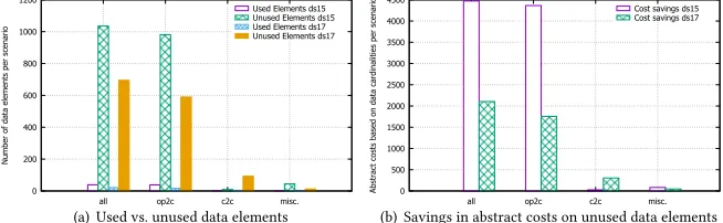
to “ray tracing” algorithms [20]. We collect the data elements that are used or not used, where possible — we do not have sufficient design time data to do this for user defined functions or some of the message construction patterns, such as request-reply. Based on the resulting data element usages, we calculate two metrics: the comparison of used vs. unused elements in Fig. 8(a), and the savings in abstract costs on unused data elements in Fig. 8(b).
Results. There is a large amount of unused data elements per sce-nario for the OP2C scesce-narios; these are mainly web service com-munication and message mappings, for which most of the data flow can be reconstructed. This is because the predominantly used EDI and SOA interfaces (e.g., SAP IDOC, SOAP) for interoperable communication with on-premise applications define a large set of data structures and elements, which are not required by the cloud applications, and vice versa. In contrast, C2C scenarios are usually more complex, and mostly use user defined functions to transform data, which means that only a limited analysis of the data element usage is possible.
When calculating the abstract costs for the scenarios with unused fields, there is an immense cost reduction potential for the OP2C scenarios as shown in Fig. 8(b). This is achieved by adding a content filter to the beginning of the scenario, which removes unused fields. This results in a cost increase|din| =#unused elements for the content filter, but reduces the cost of each subsequent pattern up to the point were the elements are used.
Conclusions. (3) Data flows can best be reconstructed when design time data based on interoperability standards is available; and (4) a high number of unused data elements per scenario indicates where bandwidth reductions are possible.
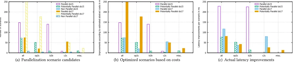
Improved Latency: Parallelization (OS-3).For the sequence-to-parallel optimization strategies from OS-3, the relevant metric is the processing latency of the integration scenario. Because of the uncer-tainty in determining whether a parallelization optimization would be beneficial, we first report on the classification of parallelization candidates in Fig. 9(a). We then report both the improvements ac-cording to our cost model in Fig. 9(b), as well as the actual measured latency in Fig. 9(c).
Results. Based on the data element level, we classify scenario can-didates asparallel, definitelynon parallel, orpotentially
parallelin Fig. 9(a). The uncertainty is due to sparse information.
From the 2015 catalog, 81% of the scenarios are classed asparallel,
orpotentially parallel, while the number for the 2017 catalog
is 53%. In both cases, the OP2C and B2B scenarios show the most improvement potential. Figure 9(b) shows the selection based on our cost model, which supports the pre-selection of all of these optimization candidates. The actual, average improvements per im-pacted scenario are shown in Fig. 9(c). The average improvements of up to 230 milliseconds per scenario must be understood in the context of the average runtime per scenario, which is 1.79 seconds. We make two observations: (a) the cost of the additional fork and join constructs in Java are high compared to those implemented in hardware [36], and the improvements could thus be even better, and (b) the length of the parallelized pattern sequence is usually short: on average 2.3 patterns in our scenario catalog.
Conclusions. (5) The parallelization requires low cost fork and join implementations; and (6) better runtime improvements might be achieved for scenarios with longer parallelizable pattern sequences.
5.2
Case Studies
We apply, analyze and discuss the proposed optimization strategies in the context of two case studies: the Replicate Material on-premise to cloud scenario from Fig. 1, as well as an SAP eDocument invoicing cloud to cloud scenario. These scenarios are part of the SAP CPI standard, and thus several users (i.e., SAP’s customers) benefit immediately from improvements. For instance, we additionally implemented a content monitor pattern [37] that allowed analysis of the SAP CPI content. This showed the Material Replicate scenario was used by 546 distinct customers in 710 integration processes copied from the standard into their workspace — each one of these users is affected by the improvement.
Replicate Material (revisited).Recall from Sect. 1 that the Repli-cate Material scenario is concerned with enriching and translating messages coming from a CRM before passing them on to a Cloud for Customer service, as in Fig. 1. As already discussed, the content enricher and the message translator can be parallelized according to the sequence to parallel optimization from OS-3. The original and resulting IPCGs are shown in Fig. 2(a) and 2(b). No throughput optimizations apply.
Latency improvements. The application of this optimization can be considered, if the latency of the resulting parallelized process is smaller than the latency of the original process, i.e. if
cost(MC)+max(cost(CE),cost(MT))+cost(JR)+cost(AGG)
0 50 100 150 200 250
all op2c b2b c2c misc.
Number of scenarios
Parallel ds15 Potentially Parallel ds15 Non Parallel ds15 Parallel ds17 Potentially Parallel ds17 Non Parallel ds17
(a) Parallelization scenario candidates
0 50 100 150 200 250
all op2c b2b c2c misc.
Improvements according to estimated abstract costs in ms
Parallel ds15 Potentially Parallel ds15 Parallel ds17 Potentially Parallel ds17
(b) Optimized scenarios based on costs
0 50 100 150 200 250
all op2c b2b c2c misc.
Latency improvements per scenario in ms
Parallel ds15 Potentially Parallel ds15 Parallel ds17 Potentially Parallel ds17
[image:10.612.62.555.93.198.2](c) Actual latency improvements
Figure 9: OS-3 “Sequence to parallel” optimization candidates on (a) integration flows, (b) optimization selection based on abstract cost model, and (3) actual latency improvements.
Subtracting max(cost(CE),cost(MT))from both sides of the inequal-ity, we are left with
cost(MC)+cost(JR)+cost(AGG)<min(cost(CE),cost(MT))
If we assume that the content enricher does not need to make an external call, its abstract cost becomescost(CE)(|din|,|dr|)=|din|, and plugging in experimental values from a pattern benchmark [38], we arrive at the inequality (with latency costs in seconds)
0.01+0.002+0.005≮min(0.005,0.27)
which tells us that the optimization is not beneficial in this case — the additional overhead is larger than the saving. However, if the content enricher does use a remote call,cost(CE)(|din|,|dr|)= |din|+|dr|, and the experimental values now saycost(CE)=0.021. Hence the optimization is worthwhile, as
0.01+0.002+0.005<min(0.021,0.27) .
Model Complexity. Following Sánchez-González et al. [42], we mea-sure the model complexity as the node count. Hence, in this case, the optimization increases the complexity by three.
Conclusions. (7) The pattern characteristics are important when deciding if an optimization strategy should be applied (e.g., local vs. remote enrichment); and (8) there are goal conflicts between the different objectives, as illustrated by the trade-off between latency reduction and increasing model complexity.
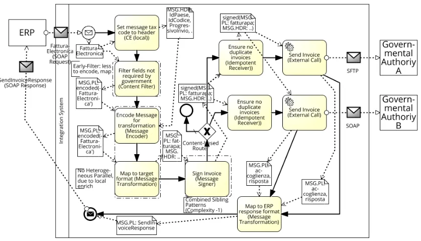
eDocuments: Italy Invoicing.The Italian government accepts electronic invoices from companies, as long as they follow reg-ulations — they have to be correctly formatted, signed, and not be sent in duplicate. Furthermore, these regulations are subject to change. This can lead to an ad-hoc integration process such as in Fig. 10 (simplified). Briefly, the companies’Fattura Electronicais used to generate afactorapadocument with special header fields (e.g.,Paese,IdCodice), then the message is signed and sent to the authorities, if it has not been sent previously. The multiple authori-ties respond with standardCoglienza,Rispostaacknowledgments, that are transformed to aSendInvoiceResponse. We transformed the BPMN model to an IPCG, tried to apply optimizations, and created a BPMN model again from the optimized IPCG.
Our heuristics for deciding in which order to try to apply differ-ent strategies are “simplification before parallelization” and “struc-ture before data”, since this seems to enable the largest number of optimizations. Hence we first try to apply OS-1 strategies: the
combine siblingsrule matches the sibling Message Signers, since the preceding content-based router is a fork. (The signer is also side-effect free, so applying this rule will not lead to observably different behavior.) Next we try OS-3 strategies. Although heteroge-neous parallelizationmatches for the CE and the Message Encoder, it is not applied since
cost(MC)+cost(JR)+cost(AGG)≮min(cost(CE),cost(ME)),
i.e., the overhead is too high, due to the low-latency, local CE. Finally, theearly-filterstrategy from OS-2 is applied for the Content Filter, inserting it between the Content Enricher and the Message Encoder. No further strategies can be applied. The resulting integration process translated back from IPCTG to BPMN is shown in Fig. 11.
Conclusions. (9) The application order OS-1, OS-3, OS-2 seems most beneficial (“simplification before parallelization”, “structure before data”); (10) an automatic translation from IPCGs to concepts like BPMN could be beneficial for connecting with existing solutions.
6
RELATED WORK
We presented related optimization techniques in Sect. 2. We now briefly situate our work within the context of other formalizations, beyond the already discussed BPMN [40] and PN [17] approaches. Enterprise Application Integration.Similar to the BPMN and PN notations, several domain-specific languages (DSLs) have been developed that describe integration scenarios. Apart from the EIP icon notation [23], there is also the Java-based Apache Camel DSL [24], and the UML-based Guaraná DSL [18]. However, none of these languages aim to be optimization-friendly formal integration scenario representations. Conversely, we do not strive to build an-other integration DSL. Instead we claim that all of the integration scenarios expressed in such languages can be formally represented in our formalism, so that optimizations can be determined that can be used to rewrite the scenarios.
Figure 10: Country-specific invoicing (potential improvements as BPMN Group.)
Figure 11: Invoice processing from Fig. 10 after application of strategies OS-1–3.
nets as a language instead of integration patterns, similar to the approach of Fahland and Gierds [17].
Business Process Management.Early algorithmic work by Sadiq and Orlowska [41] applied reduction rules to workflow graphs for the visual identification of structural conflicts (e.g., deadlocks) in
[image:11.612.93.512.371.611.2]allows to analyze the life cycle of an object, and check data compli-ance rules. Although this adds a view on the required data, it does not propose optimizations for the extended EIPs. The main focus is rather on the object life cycle analysis of the process.
7
CONCLUSIONS
This work addresses an important shortcoming in EAI research, namely the lack of optimization strategies, and the informality of de-scriptions of pattern compositions and optimizations (cf. RQ1–RQ3). We approached the questions by compiling a catalog of optimization strategies from the literature. We then developed a formalization of pattern compositions in order to precisely define optimizations, which we evaluated on data sets containing in total over 900 real world integration scenarios, and two brief case studies. We con-clude that formalization and optimizations are relevant even for experienced integration experts (conclusions 1–2), with interesting choices (conclusions 3–4, 6), implementation details (conclusions 5, 10) and trade-offs (conclusions 7–9).
In further work, we plan to incorporate dynamic aspects into the formalization of patterns, for a more precise cost semantics. In addition, purely data related techniques like message indexing, fork path re-ordering and merging of conditions can be analyzed for their effects. Finally, multi-objective optimizations and heuristics for graph rewriting on the process level have to be further studied.
ACKNOWLEDGMENTS
We thank Jonas Kandels for implementation support, and the anony-mous reviewers for suggestions and comments.
REFERENCES
[1] S. Abiteboul, M. Arenas, P. Barceló, M. Bienvenu, D. Calvanese, C. David, R. Hull, E. Hüllermeier, B. Kimelfeld, L. Libkin, W. Martens, T. Milo, F. Murlak, F. Neven, M. Ortiz, T. Schwentick, J. Stoyanovich, J. Su, D. Suciu, V. Vianu, and K. Yi. Research directions for principles of data management (abridged). SIGMOD Record, 45(4):5–17, 2017.
[2] K. Agrawal, A. Benoit, L. Magnan, and Y. Robert. Scheduling algorithms for linear workflow optimization. InIPDPS, pages 1–12, 2010.
[3] S. G. Ahmad, C. S. Liew, M. M. Rafique, E. U. Munir, and S. U. Khan. Data-intensive workflow optimization based on application task graph partitioning in heterogeneous computing systems. InIEEE BdCloud, pages 129–136, 2014. [4] F. E. Allen. Control flow analysis.SIGPLAN Notices, 5(7):1–19, 1970. [5] D. Battré, S. Ewen, F. Hueske, O. Kao, V. Markl, and D. Warneke. Nephele/
PACTs: a programming model and execution framework for web-scale analytical processing. InSoCC, pages 119–130, 2010.
[6] A. Benoit, M. Coqblin, J.-M. Nicod, L. Philippe, and V. Rehn-Sonigo. Throughput optimization for pipeline workflow scheduling with setup times. InEuro-Par Workshops, pages 57–67, 2012.
[7] L. F. Bittencourt and E. R. M. Madeira. Hcoc: a cost optimization algorithm for workflow scheduling in hybrid clouds.Journal of Internet Services and Applications, 2(3):207–227, 2011.
[8] A. Böhm.Building Scalable, Distributed Applications with Declarative Messaging. PhD thesis, University of Mannheim, 2010.
[9] A. Böhm and C. Kanne. Demaq/transscale: Automated distribution and scalability for declarative applications.Information Systems, 36(3):565–578, 2011. [10] M. Böhm, D. Habich, W. Lehner, and U. Wloka. Systemübergreifende
Kostennor-malisierung für Integrationsprozesse. InBTW, pages 67–86, 2009.
[11] M. Böhm, D. Habich, S. Preissler, W. Lehner, and U. Wloka. Cost-based vector-ization of instance-based integration processes.Information Systems, 36(1):3–29, 2011.
[12] M. Böhm, U. Wloka, D. Habich, and W. Lehner. Model-driven generation and optimization of complex integration processes. InICEIS (1), pages 131–136, 2008. [13] C. Cabanillas, M. Resinas, A. Ruiz-Cortés, and A. Awad. Automatic generation of a data-centered view of business processes. InCAiSE, pages 352–366. Springer, 2011.
[14] H. Ehrig, K. Ehrig, U. Prange, and G. Taentzer.Fundamentals of Algebraic Graph Transformation. Monographs in Theoretical Computer Science. Springer, 2006.
[15] H. Ehrig, M. Pfender, and H. J. Schneider. Graph-grammars: An algebraic ap-proach. InSwitching and Automata Theory, pages 167–180, 1973.
[16] D. Eyers, A. Gal, H.-A. Jacobsen, and M. Weidlich. Integrating Process-Oriented and Event-Based Systems (Dagstuhl Seminar 16341).Dagstuhl Reports, 6(8):21–64, 2017.
[17] D. Fahland and C. Gierds. Analyzing and completing middleware designs for enterprise integration using coloured petri nets. InCAiSE, pages 400–416, 2013. [18] R. Z. Frantz, A. M. Reina Quintero, and R. Corchuelo. A domain-specific language to design enterprise application integration solutions.International Journal of Cooperative Information Systems, 20(02):143–176, 2011.
[19] J. R. Getta. Static optimization of data integration plans in global information systems. InICEIS, pages 141–150, 2011.
[20] A. S. Glassner.An introduction to ray tracing. Elsevier, 1989.
[21] A. Habel and D. Plump. Relabelling in graph transformation. InICGT, volume 2505, pages 135–147. Springer, 2002.
[22] I. Habib, A. Anjum, R. Mcclatchey, and O. Rana. Adapting scientific workflow structures using multi-objective optimization strategies.TAAS, 8(1):4, 2013. [23] G. Hohpe and B. Woolf.Enterprise integration patterns: Designing, building, and
deploying messaging solutions. Addison-Wesley, 2004. [24] C. Ibsen and J. Anstey.Camel in Action. Manning, 2010.
[25] A. Kissinger, A. Merry, and M. Soloviev. Pattern graph rewrite systems. InDCM, pages 54–66, 2012.
[26] B. Kitchenham. Procedures for performing systematic reviews.Keele, UK, Keele University, 33(2004):1–26, 2004.
[27] G. Kougka and A. Gounaris. Optimization of data-intensive flows: Is it needed? Is it solved? InDOLAP, pages 95–98. ACM, 2014.
[28] G. Kougka, A. Gounaris, and A. Simitsis. The many faces of data-centric workflow optimization: A survey.CoRR, abs/1701.07723, 2017.
[29] P. Mederly, M. Lekav`y, M. Závodský, and P. Navra. Construction of messaging-based enterprise integration solutions using AI planning. InCEE-SET, pages 16–29, 2009.
[30] J. M. Mendes, P. Leitão, A. W. Colombo, and F. Restivo. High-level petri nets for the process description and control in service-oriented manufacturing systems. International Journal of Production Research, 50(6):1650–1665, 2012.
[31] F. Niedermann, S. Radeschütz, and B. Mitschang. Business process optimization using formalized patterns.BIS, 2011.
[32] F. Niedermann and H. Schwarz. Deep business optimization: Making business process optimization theory work in practice. InEnterprise, Business-Process and Information Systems Modeling, pages 88–102. Springer, 2011.
[33] K. Peffers, T. Tuunanen, M. A. Rothenberger, and S. Chatterjee. A design science research methodology for information systems research.JMIS, 24(3):45–77, 2007. [34] D. Plump and A. Habel. Graph unification and matching. InTAGT, pages 75–88,
1994.
[35] D. Ritter. Database processes for application integration. InBICOD, pages 49–61, 2017.
[36] D. Ritter, J. Dann, N. May, and S. Rinderle-Ma. Hardware accelerated application integration processing: Industry paper. InACM DEBS, pages 215–226, 2017. [37] D. Ritter, N. May, and S. Rinderle-Ma. Patterns for emerging application
integra-tion scenarios: A survey.Information Systems, 67:36 – 57, 2017.
[38] D. Ritter, N. May, K. Sachs, and S. Rinderle-Ma. Benchmarking integration pattern implementations. InACM DEBS, pages 125–136, 2016.
[39] D. Ritter and S. Rinderle-Ma. Toward application integration with multimedia data. InIEEE EDOC, pages 103–112, 2017.
[40] D. Ritter and J. Sosulski. Exception handling in message-based integration systems and modeling using BPMN.Int. J. Cooperative Inf. Syst, 25(2):1–38, 2016. [41] W. Sadiq and M. E. Orlowska. Analyzing process models using graph reduction
techniques.Information systems, 25(2):117–134, 2000.
[42] L. Sánchez-González, F. García, J. Mendling, F. Ruiz, and M. Piattini. Prediction of business process model quality based on structural metrics. InER, pages 458–463, 2010.
[43] T. Tirapat, O. Udomkasemsub, X. Li, and T. Achalakul. Cost optimization for scientific workflow execution on cloud computing. InICPADS, pages 663–668, 2013.
[44] K. Vergidis, A. Tiwari, and B. Majeed. Business process analysis and optimization: Beyond reengineering.IEEE Transactions on SMC, Part C, 38(1):69–82, 2008. [45] M. Vrhovnik, H. Schwarz, O. Suhre, B. Mitschang, V. Markl, A. Maier, and T. Kraft.
An approach to optimize data processing in business processes. InVLDB, pages 615–626, 2007.