Mechatronic Actuators
Mr. Scott Brady* Prof. Xiu T. Yan**
*University of Strathclyde, Glasgow, Scotland. G1 1XJ Tel: +44141 574 5197 ([email protected]) ** University of Strathclyde, Glasgow, Scotland. G1 1XJ Tel: +44141 574 2852 ([email protected])
Abstract: This paper will cover use of a component selection tool in understanding and forecasting the actuation needs of robotic systems in the future. As part of an ongoing work, a component selection tool to assist mechatronics engineers has been developed. Pursuant to the conference’s theme, this paper will focus on how effective the tool is in nurturing innovation of new actuation components and systems. Discussion will take place covering topics such as: development and intended primary and secondary applications of the component selection tool; applying the tool to component selection; how the tool can be used to identify ideal requirements in a design process; how the tool can be used to generate solutions which attempt to encompass what is required of an ideal solution; how the tool is relevant to mechatronics presently; and, how ongoing use could affect a paradigmatic shift in the field of mechatronic systems design and configuration.
Keywords: Mechatronics, Component, Selection, Actuator, Robotics
1. INTRODUCTION
The design of robotic and mechatronic systems is a field in which there are tremendous degrees of interest from a great many perspectives. Pop culture frequently entertains discourse on the ways in which innovative robots and artificial intelligence are set to change the way we live our lives in the coming decades. This discussion is merely a symptom of the growth which has taken place in this industry over the last 20 – 30 years; from self-checkouts to automated industrial machinery the impacts of mechatronics and automation have been felt somewhat ubiquitously.
As a result of this industry growth, the number of mechatronic systems in use has increased. The intended applications of robotic systems have also become more diversified, ranging from experimental robot arms for space craft inspection [1] to mechatronic “dogs” capable of navigating a human-friendly environment [2]. With this, requirements on mechatronics engineers to produce quality, versatile systems have also increased. This being so, providing assistance to such professionals would seem to be a reasonable course of action. Across engineering disciplines, assistance is regularly provided to engineers through the use of tools and methods which have been developed. For example: materials selection is aided by Cambridge Engineering Selector (CES) and the work of Michael F. Ashby [3]; quality and reliability is assisted by tools such as FMEA (failure mode and effects analysis); and, there are countless tools available to engineering designers at a concept development level. This barely scratches the surface of tools available to engineers, but each has a common purpose: to enhance the effectiveness and reduce the burden on engineers when designing new systems. Through review of literature and experience, no tool or approach has been encountered which wholly facilitates component selection for
actuation packages in mechatronic systems. This seems counter-intuitive, as this element of system design engineering is no- less complex than materials selection, for instance; in fact, it may even be reasonable to suggest that selection of components is more difficult due to the changing performance traits of components, as well as the way different components interact with one another. It would be useful to investigate whether a novel approach may in some way enhance component selection procedures for robot joint actuator components.
This paper briefly discusses the mode through which component selection has been proposed to be tackled; however, focus in this paper will be on the implications this may have towards development of future mechatronic systems, rather than the idiosyncrasies of the tool itself.
The paper is structured as follows: section 2 discusses related works and their implications; section 3 will introduce the component selection approach proposed; section 4 will briefly discuss applications of the tool to date and its effectiveness there; section 5 will cover the impacts on mechatronics as a field and how the tool can be used to identify the ideal requirements of an actuator on a case-by-case approach; and, section 6 will conclude by remarking on the significance of the work in the field of mechatronics.
2. RELATED WORKS
Instead, engineers tend to rely on paradigmatic selection of components, or their own expert understanding and experience to select components. This is akin to the approach taken to selection of materials prior to the induction of CES and its associated works [3]. This being so, the same issues as with materials can reasonably be assumed to be somewhat prevalent; that is, non-optimal solutions being put forward. As such, this work attempted to replicate the steps taken by Ashby and apply it to the development of a new approach to the selection of components. It is anticipated that doing so will allow greater rigour in the selection process.
Fig 1: Example of an Ashby graph [3].
An example Ashby graph is presented in figure 1. The specifics of content considered in the graph are not directly relevant to the work undertaken here; however, the underlying principles on which it is based are of great significance. Essentially, the graph represents the performance of materials in terms of defined criteria. The range of material capabilities are represented by the bubbles (or “kingdoms”) of varying colour, and the x and y points of the periphery of the kingdom correspond to the respective limits for that materials. The work undertaken in this project is proposed to be represented in the same way, allowing intuitive and comparative selection to take place at all stages of the design process. For example, in the above material selection chart, if an engineer required a material of density 100kg/m3, then the designer knows that their choices are restricted to foams with Young’s modulus of approx. 1x10⁻³ GPa to approx. 0.5 GPa. At the next stage of design the engineer can then determine whether flexible polymer foams or rigid polymer foams are best suited for the application.
Another noteworthy aspect of this approach is that changing the criteria whilst still representing the same materials would
yield a graph with different positioning of the “kingdoms”. For an instance of density vs cost this would yield the most dense and most expensive materials in the top right of the graph, whilst the least dense and least expensive would be in the bottom left of the graph. This ongoing research project is examining the potential effects of applying this approach to engineering design in component selection for robotic arm system; however, this paper asks the question “what are the potential ramifications of such an approach to component selection in terms of reinventing mechatronics?”, with the question being answered in the concluding remarks of this paper.
3. DEVELOPMENT OF COMPONENT SELECTION APPROACH
This section will briefly explore the approach and choices made in the development of the selection tool, starting from conception of the tool and development of its form.
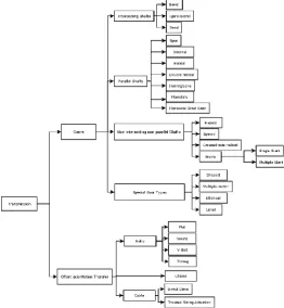
At the outset of this work several other works were referenced in order to gain a deeper understanding of the technologies used in robot arm actuation [10] [11] [12] [13] [14] [15]. This enabled a good understanding of typical technologies employed in joint actuation of robot arms. This led to the broad approximation that components to be considered in this project were drive systems (motor, hydraulic, etc.), transmission systems, sensory apparatus, and other relevant machine elements (bearings and bushings). With reference to figure 2, it can be seen then that in a typical instance this means that consideration of controller boards, power converters, etc. will be omitted from consideration at this stage.
[image:2.595.309.566.452.658.2]Fig 3: Abstract modelling of mechatronic actuation component relations.
As has been previously mentioned, the work of Ashby on materials selection greatly informed the development of this work. As such, Ashby’s work was used as a useful guide in attempting to create a similar approach for component selection processes.
To approach the problem of representing component performance graphically, some well-known actuator component developers were used as the source for compiling data on actuator operating characteristics. This includes developers such as Parker Hannifin Corporation [16], Maxon, and RS Components. This process allowed information on motors, transmissions, and sensory apparatus to be co-opted for the purposes of this project. It is an assumption that data from other manufacturers could easily be added at a later date without much difficulty; however, in order to assess the viability of the approach the spectrum of component manufacturers to consider was kept purposefully small at this stage.
After compilation of the applicable data it was deemed essential to understand thoroughly their relationships with one another, patterns within use of certain component types, and how they are applied in robotic actuators. Attempts were made at this stage to source models of this ilk; however, it was found that peer-reviewed models elucidating the relationships were not available. Those encountered tended to be from manufacturer websites, and often their representations varied. Models of robotics specific electric motors, transmission systems, and sensory apparatus were all sought after, but no peer-reviewed results were found. As such, a bespoke model of robot joint actuation was developed, enabling clear representation of the types of actuation which can demonstrably be used, and the manner in which they relate to other candidate approaches to actuation; the model is described in the remainder of this section.
First of all, the relationship between joint actuation components was modelled at a highly abstracted level, see figure 3. This proved to be complex due to crossover of different types of actuation. After iteration, the abstracted model reached a satisfactory level of completion. As the model attempts to capture everything from hydraulics to linear electric motors, it was felt that the scope was too large. In order to understand how effective this new approach to component selection could be the scope was narrowed, thus, only electric rotational motors were to be considered.
The next task required detailing of how rotational actuation in a joint can be achieved pursuant to electrical motors’ use. This entailed considering motors themselves, as well as transmission, sensors, brakes, and other machine elements. Modelling of this work helped to clarify the possible relationships between these component types, specifically as it pertains to robot arm actuation. Part of this process is shown in figure 4, where transmission elements of manipulator arms are represented.
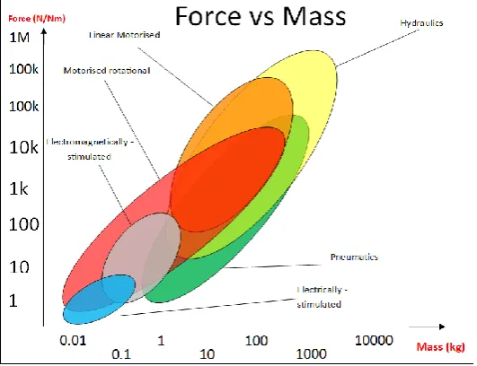
[image:3.595.304.567.454.739.2]Finally, as mentioned throughout, the work is represented graphically to show the performance of actuator components. In figures 5 and 6 high-level representations of electric motors when compared with other actuators (based on figure 3’s relationships) are given. As can be seen, the y-axis parameter is changed between the figures, altering the form of the graphs. Doing so should (it is hypothesised) allow quick component comparisons to be made by engineers based on the requirements of their project.
This section is concluded by delineating the way in which the covered processes of this approach to component selection combine to allow component selection to take place. In essence, a database of actuator performance informs the graphical representation of information, both of which are utilised to inform the development of the model. These sections have then been considered when developing guidelines to use all these tools effectively in concert to produce quality outputs in terms of component selection.
Fig 5: Cost Vs Mass of Actuation Candidates at High-Level
Fig 6: Force Vs Mass of Actuation Candidates at High-Level
4. APPLICATIONS OF THE COMPONENT SELECTION TOOL
As the work is still ongoing, there have been limited applications of the tool so far. A pilot study has been undertaken which employed the tool in a limited component selection process. This work has highlighted some of the issues: the tool tended to be of more use during conceptual development, and its effectiveness begun to wilt in embodiment design and detailed design phases. It is crucial to note, however, that this pilot study also allowed a number of changes to be made to the work which it is expected will improve the efficacy of the approach in other design phases.
As part of the pilot study the effectiveness of the graphs in representing “gaps” in actuation capability were also explored in a limited capacity, with positive results. It was found that the graphs were a very useful tool in allowing designers to quickly and easily determine where gaps exist, and what could be done to fill the gaps. During pilot study the process of utilising the design tool in order to fill the “gaps” was not assessed; this is to be assessed imminently and the results of this will be discussed further at a later stage. The proposed mechanism through which the gaps could be filled is addressed in the following section.
5. REINVENTING MECHATRONIC ACTUATION SYSTEMS
In the last section allusions were made as to how the tool can be exploited in order to identify areas where an ideal actuator can be developed for application to a specific task. What is meant by this is discussed in the remainder of this section.
If an engineer or engineering team are working on a project they will typically have design specifications. These specifications will cover performance, costs, etc. When making choices regarding the actuation components to be used it may be found that the desired performance, cost, mass, or some other criteria is not quite able to be reached. Therefore components which aren’t quite right, but are sufficient, will be made use of and augmented in some mechanical (or other) manner.
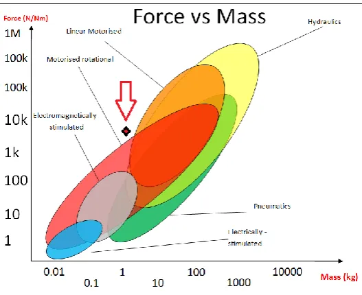
Discussed earlier was the use of graphical methods in component selection and how the “kingdoms” represent the capability of the component under consideration. What happens when a requirement for a project falls outside of one of these “kingdoms” and lands instead in a blank region of the charts? With reference to figure 7, one can see that for a mass of 1 kg, there are no means of achieving a direct drive force or torque of 10 kNm or 10 kN. This region is highlighted by the red dot in figure 7. Should this happen one of two things is liable to occur in a component selection procedure. Either:
[image:4.595.26.292.454.658.2]required. This augmentation facilitates acceptable performance; and,
[image:5.595.28.292.195.410.2]2. Alternatively, there may be instances where some arrangement which is not ideal is put in place; i.e. an instance where gearing or other augmentation still doesn’t allow the performance to operate as required. In this instance the components selected do the job, but do not perform in an ideal manner.
Fig 7: Component selection graph.
The second of these instances described is where this tool could perhaps become very useful; i.e. in instances where a component is required, but typical COTS (commercial off-the-shelf) solutions do not provide suitable scope to resolutely fulfil the needs, even with augmentation. It is acknowledged, of course, that this development process is not likely to yield ready-to-go outputs; there will and must be some development and refinement towards effective implementation of any new actuator. What this approach does offer is a methodical means to generate new actuation concepts in a targeted and rigorous manner. Through use of the graphs, which illustrate performance, the engineer can clearly define what requirements are not met by existing actuators and implement steps towards generating a solution in which desired performance is provided.
Perhaps the best aspect of this approach to component performance representation is that the performance of a component can be viewed quickly and easily with respect to other options available. Similarly, when requirements are not met – as in the example represented in figure 7 – one can also quickly and easily see the existing methods which are closest to achieving the required outputs. This opens avenues to inspire “grafting” or “hybridisation” of various component attributes to achieve a better solution. In the instance in figure 7, the requirement is less mass and more output force/torque. A suggestion might then be, relative to the proximal components, that characteristics of hydraulics and motorised methods be grafted to attempt to yield a new solution. This is
a crude example, but it illustrates the notion under consideration; the same notion is applied by Ashby in his materials selection work: “[of the charts]... other parts are empty even though, in principle, they are accessible. If they were accessed, the new materials that lay there could allow novel design possibilities”. It is expected that at higher levels of fidelity within the component representation graphs some positive results will be achieved towards filling these “empty spaces”. This will thusly allow testing of to what extent new components which lie in these empty spaces can be used to elicit novel design possibilities.
As well as using the graphs to identify new solutions, the use of the component selection tool itself could also be used in the development and refinement of any new actuation concepts proffered. This has not been explored at this stage, but will be in the coming months.
6. CONCLUSIONS
Based on the information gained from pilot studies, it is suggested that the component selection tool is useful during initial concept selection. It is expected that with tweaks the methods will be more useful in terms of the applications to embodiment and detail design stages. If this process is proven to be effective further development may yield a new approach to component selection in mechatronic systems. This could potentially change the design approach taken in the field of mechatronics.
More pertinent to this paper is the applicability to the development of new actuators using this approach. Again, from pilot testing it has been seen that the tool is effective in identifying the gaps which exist, and – importantly – it is also useful in allowing the engineer to see existing candidate components with performance characteristics proximal to that of the performance which is required. This is important, as it assists the engineer in making connections between what are probably the best types of technology to look towards in terms of hybridising to develop an actuator component with the required performance; tabulated or qualitative content is not as effective in doing this. This approach and its effectiveness have already been described and discussed in previous sections. At this stage it is sufficient to say that there are certainly some benefits to this approach, in that it is useful to the engineer as an identifying tool. Ongoing work will provide further insights into the extent of these effects.
Most modern textbooks discussing materials selection will tend to open with their own idiosyncratic insights on materials selection before deferring to the Ashby approach, using graphical selection. Ashby’s approach has become the standardised approach to materials selection. This work seeks to understand whether the same paradigmatic shift could feasibly be applied to component selection, and how this will affect mechatronics both in the present and in the future.
6. REFERENCES
[1] J. S. Mehling, M. A. Diftler, M. Chu, and M. Valvo, “A minimally invasive tendril robot for in-space inspection,” Proc. First IEEE/RAS-EMBS Int. Conf. Biomed. Robot. Biomechatronics, 2006, BioRob 2006, vol. 2006, pp. 690–695, 2006.
[2] Guardian, “Boston Dynamics is teaching its robot dog to fight back against humans,” The Guardian, 2018. [Online]. Available:
https://www.theguardian.com/technology/2018/feb/2 1/boston-dynamics-teaching-robot-dog-fight-back-humans.
[3] M. F. Ashby, Materials Selection in Mechanical Design, 3rd ed. Elsevier, 1992.
[4] P. Hamilton, UNIT SELECTION - ELECTRIC MOTOR - PAT HAMILTON.pdf. 1988.
[5] A. Hughes, Electric Motors and Drives. Leeds: Newnes, 2005.
[6] E. Prestes et al., “Towards a core ontology for robotics and automation,” Rob. Auton. Syst., vol. 61, no. 11, pp. 1193–1204, 2013.
[7] C. Schlenoff et al., “An IEEE Standard Ontology for Robotics and Automation,” pp. 1337–1342, 2012.
[8] A. Nilsson, R. Muradore, K. Nilsson, and P. Fiorini, “Ontology for Robotics : a Roadmap,” 2009.
[9] P. Fiorini et al., “Extensions to the core ontology for robotics and automation,” Robot. Comput. Integr. Manuf., no. September 2014, 2014.
[10] R. Bischoff et al., “The KUKA-DLR Lightweight Robot arm - a new reference platform for robotics research and manufacturing,” Robot. (ISR), 2010 41st Int. Symp. 2010 6th Ger. Conf. Robot., pp. 1–8, 2010.
[11] a. Albu‐ Schäffer, S. Haddadin, C. Ott, a. Stemmer, T. Wimböck, and G. Hirzinger, “The DLR
lightweight robot: design and control concepts for robots in human environments,” Ind. Robot An Int. J., vol. 34, no. 5, pp. 376–385, 2007.
[12] S. Haddadin, a Albu-Schäffer, and G. Hirzinger, “Safety Evaluation of Physical Human-Robot Interaction via Crash-Testing,” Robot. Sci. Syst. Conf. (RSS2007), Atlanta, USA, pp. 217–224, 2007.
[13] R. S. Colladay, NASA Space Technology Roadmaps and Priorities : Restoring NASA ’ s Technological Edge and Paving the Way for a New Era in Space
Steering Committee for NASA Technology Roadmaps. 2012.
[14] A. Ellery, An Introduction to Space Robotics. 2000.
[15] J. J. Craig, Introduction to Robotics: Mechanics and Control, Third. Pearson, 2004.
![Fig 1: Example of an Ashby graph [3].](https://thumb-us.123doks.com/thumbv2/123dok_us/1366774.90057/2.595.309.566.452.658/fig-example-ashby-graph.webp)