UNIVERSITI TEKNIKAL MALAYSIA MELAKA
FACULTY OF ELECTRICAL ENGINEERING UNIVERSITI TEKNIKAL MALAYSIA MELAKA
FINAL YEAR
PROJECT REPORT BEKU 4894
Mobile Robot Navigation System: Line Following Robot by using PID algorithm
Ling Sing Yip
Bachelor of Mechatronics Engineering
1
"I hereby deClare read through this report entitle "Mobile Robot Navigation System: Line Following Robot by using PID algorithm" and found that it has comply the partial fulfillment for awarding the degree of Bachelor of Mechatronic Engineering"
Signature
...
~
...
~
...
~
:
... .Supervisor's Name
,
b
,
OR. MUHAMMAD FAHMI BINMiSKON
.
. Df:
f
0h~
l ...
!
.~
...
~!
.S
t
9.
~;~
i
S
KY:u~:a~:~!;:ik
Universiti Teknikal Malaysia Mel aka
MOBILE ROBOT NAVIGATION SYSTEM: LINE FOLLOWING ROBOT BY
USING PID ALGORITHM
LING SING YIP
A report submitted in partial fulf"illm.ent of the requirements for the degree of
Bachelor of Mechatronic Engineering
Faculty of Electrical Engineering
UNIVERSITI TEKNIKAL MALAYSIA MELAKA
2014/2015
lll
I declare that this report entitle "Mobile Robot Navigation System: Line Following Robot by using PID Algorithm" is the result of my own research except as cited in the reference. The report has not been accepted for any degree and is not concurrently submitted in candidature of any other degree.
Signature
···
·
·
·
~
·
···
·
···
··
···
·
···
·
·
·
··
Name
.
.
.
.
~.r.~~.Si:~
..
Y.1.P. ..
..
..
..
.
.
..
.
..
.
..
.
IV
v
ACKNOWLEDGEMENT
In preparing this report, I would like to express my sincere appreciation to my supervisor, Dr Muhammad Fabmi Bin Miskon that gave me the opportunity and accepted me to be his supervise. As my supervisor, he gave me encouragement, guidance critics and friendship. Without his support and interest, this project would not have been same as presented here.
VI
ABSTRACT
Vll
ABSTRAK
Menurut kajian World Health Ranking tahun 2011, Malaysia telah diiktirafkan
sebagai Negara berada dalam kedudukan 20 teratas berdasarkan kemalangan maut berlaku
di jalan raya. Oleh hal yang demikian, robot berasaskan konsep navigasi tanpa kawalan manusia wajarnya dicipta untuk mengurangkan kadar kemalangan jalan raya. Kertas kerja
ini akan membentangkan tentang robot pengikut garisan dengan menggunakan sistem
kawalan PID algoritma Objektifkertas kerja ini adalah untuk menghasilkan robot pengikut
garisan yang berkelajuan tinggi dan tepat ketika mengikut garisan dengan menggukan
sistem kawalan PID algoritma. Sistem kawalan PID algoritma digunakan untuk
mengurangkan kegoyangan ketika bergerak dan memperbetulkan gerakan jika ianya
terkeluar dari garisan. Robot ini merupakan robot yang pintar kerana mampu bergerak
mengikuti garis hitam yang dilukis pada permukaan putih serta dapat mengawal
pergerakan dengan lancar. Terdapat 2 eksperimen yang di jalankan untuk mencapai
objektif kertas kerja ini. Eksperimen yang pertama adalah unutk menguji prestasi robot
pengikut garisan ketika bergerak dalam kelajuan tinggi, manakala eksperimen kedua
adalah untuk menguji kepekaan sensor yang mempengaruhi ketepatan pergerakan robot.
Hasil kajian dari eksperimen pertama menunjukkan bahawa kawalan PID lebih pantas dan
tepat berbanding kawalan P dengan mengambil masa 10 saat untuk melengkapkan satu
pusingan berbandingkan kawalan P mengambil masa 14.11 saat. Untuk ujian ketepatan,
purata ralat yang dikesan menggunakan kawalan PID ialah -0.7333 manakala untuk
kawalan P ialah -1.0556. Dengan melaksanakan kawalan PID pada sistem, ia akan menghampiri nilai yang dikendendaki (zero) berbanding dengan kawalan P. Eksperimen
terakhir menunjukkan bahawa jarak antara permukaan landasan dan sensor akan
mempengaruhi prestasi iaitu kepekaan sensor tersebut. Hasil kajian menunjukkan sensor
tersebut mestilah berada di atas paras 0.6cm daripada permukaan landasan untuk
CHAPTER
1
2
TABLE OF CONTENTS
TITLE
ACKNOWLEDGEMENT
ABSTRACT
TABLE OF CONTENTS
LIST OF TABLES
LIST OF FIGURES
INTRODUCTION
1.1 Motivation
1.2 Problem Statement
1.3 Project Objective
1.4 Scope of the Project
1.5 Report Outline
LITERATURE REVIEW
2.1 Introduction
2.1.1 History of PID Controller
2.2 Theoretical Background ofPID algorithm
2.2.1 Proportional term
2.2.2 Integral term
2.2.3 Derivative term
2.3 Why Implementing PID control for line following robot
2.3.1 Proportional Control
2.3.2 Derivative Control
2.3 .3 Integral Control
2.4 Comparison among line following with PID and without
lX
PID algorithm
2.5 Available Solutions Trade off from previous study 15
2.5.1 Microcontroller 19
2.5.2 Sensors 20
2.5.3 AcD1ators 22
2.6 Summary 24
3 RESEARCH METHODOLOGY 25
3.1 Introduction 25
3.2 Project Methodology Flowchart 26
3.3 The Process Flow diagram 27
3.4 Hardware Development 28
3.4.1 Microcontroller 28
3.4 .1.1 Physical Characteristic 29
3.4.2 Robot Platform 30
3.4.3 Sensor array board 32
3 .4.4 Circuit Design 34
3.5 Track Specification 35
3.5 .1 Calculation of the track distance 34
3.6 Turning PID Control 37
3.7 Basic Programming Equation for Line Following Robot 38
3.8 Experiment Setup 39
3.8.1 Experiment 1: Sensitivity of sensor 39
3 .8.1.1 Circuit Design of Line Sensor 40
3.8.2.2 Experiment Process Flow Diagram 41
3.8.2 Experiment 2: Performance Analysis 43
3.8.2.1 Experiment Process Flow Diagram 45
3.9 Precaution on replicability and reliability issues 47
4 RESULT AND DISCUSSION 48
4.1 Introduction 48
4.2 Result of experiment to test the sensitivity of the sensor 48
4.3 Compare between the performance ofPID and P 50
Controller
5 CONCLUSION AND FUTURE WORK
5.1 Conclusion
5.2 Recommendation for future research
REFERENCES
59
59
61
62
XI
LIST OF TABLES
TABLES TITLE PAGE
2.1 Comparison of line following robot 17
2.2 List of detail of the controller from previous 19
study
2.3 List of detail of the sensor from previous study 21 2.4 List of detail of the actuator from previous study 22
3.1 Summary of Arduino UNO 29
3.2 The full range of values of sensor 33
Xll
[image:13.597.43.474.133.777.2]LIST OF FIGURES
FIGURES TITLE Page
1.1 Number of accidents, Malaysia, 2005-2009 1
1.2 Number of traffic and highway accidents, Malaysia, 2
2004-2008
1.3 Volvo self-driving line following car by use of 3
magnets
2.1 Line tracking navigation principle on the line 6
follower robot
2.2 A block diagram of a PID controller in a feedback 8
loop
2.3 Position robot relative to the setpoint 10
2.4 Robot steers in proportional to Cross Track Error 10
2.5 Robot is on the straight line and CTE is zero 11
2.6 Robot keep oscillating due to proportional control 11
2.7 Robot countersteer before reaching set point 12
2.8 Robot travel parallel to the set point by only apply 12
Proportional and Derivative control
2.9 Integral control let the robot turn to setpoint 13 2.10 Conventional line following robot follow a line. 14
2.11 Robot movement by apply PID algorithm 14
2.12 Smart car structure by D.Sivaraj 15
2.13 Smart car system architecture by D.Sivaraj 16
3.1 Closed loop system for line following robot 25
3.2 Methodology of Project 26
3.3 Flow chart of Overall Process of Project 27
3.4 Arduino Uno 28
3.5 Top view of the mobile robot 30
Xlll
3.7 Front view of mobile robot platform 31
3.8 Back view of mobile robot platforms 31
3.9 Mounting platform for sensor array and gear motor 31
3.10 Placement of IR sensor 32
3.11 Back view of the sensor circuit board 32 3.12 Front view of the sensor circuit board 33
3.13 Circuit diagram 34
3.14 Track of experiment 35
3.15 Experimental setup for test sensitivity of sensor Real 39
3.16 Circuit of Line sensor 40
3.17 Experiment Setup 40
3.18 Flow Chart for Sensor Experiments Procedure 41
3.19 Experiment Setup 43
3.20 Real experiment Setup 43
3.21 Flowchart of Performance Analysis Experiment 45
Procedure
4.1 Output voltages vs. Distance on black surface 48
4.2 Output voltages vs. Distance on White surface 49
4.3 Time taken versus PWM value 50
4.4 Velocity versus PWM value 52
4.5 Error versus Time 54
4.6 Kp Versus PWM 56
4.7 Kd Versus PWM 57
XIV
LIST OF APPENDICES
APPENDIX TITLE PAGE
A Table result of Output Voltage Varying Distance 64 from the Surface
B Result Without PID Controller I P Controller 65 Table of Time taken versus PWM value 65
Table ofVelocity versus PWM value 66
c
Result Impementing of PID controller 67 Table of Time taken versus PWM value 67Table of Velocity versus PWM value 68
Table of Kp, Ki and Kd value versus PWM value 69 Table of result by implementing PID controller when 70
the PWM value set at 120
D Gantt chart of Research Activities 76
E Programming for Line Following Robot with PID 77 controller
F Programming for Line Following Robot without PID 81
[image:15.595.41.483.79.497.2]1
CHAPTER 1
INTRODUCTION
1.1 Motivation
[image:16.595.95.501.405.620.2]The World Health Ranking 2011 has ranked that Malaysia are the top 20 countries with the most death cause by road accident. Road traffic accidents have been identified top cause of death in Malaysia after heart disease, stroke and pneumonia. Based on report by the Department of Road Safety Malaysia, there were increments of 21 percent in the number of vehicles involved in car accidents from year 2005 until 2009. [19]
Figure 1.1: Number of accidents, Malaysia, 2005-2009 [1]
2
Figure1.2: Number of traffic and highway accidents, Malaysia, 2004-2008 [1]
3
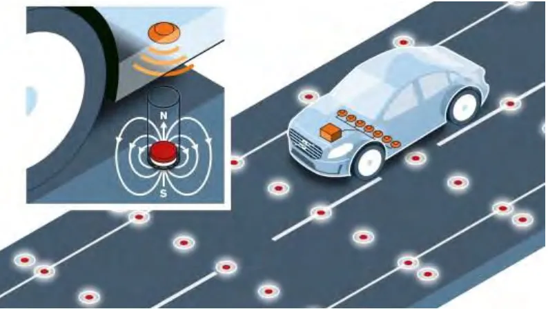
Figure 1.3: Volvo self-driving line following car by use of magnets Source: https://www.media.volvocars.com/global/en-gb/media/pressreleases/140760/photos
Autonomous navigation robot is to compromise and reduce the car accident. The line following robot is under the category of autonomous navigation robot which can detect visible like detect a line or it can appear invisible like a magnetic field. Line following robot has been a dream of mankind a long time ago. Car manufacturing company, Volvo work on autonomous vehicle with a research project on line following that that use of magnets to keep self-driving cars on the road. Volvo Company pledging to have self-driving autos on 2017 [14]. Incorporating magnet-based positioning in preventive safety systems could help prevent run-off road accidents. Magnets could facilitate accuracy of winter road maintenance, which in turn could prevent damage to snow-covered objects, such as barriers and signs, near the road edge. Upon the researches made, the rate of car accident will be dramatically reduced and the dream of mankind shall be realized in near future. Autonomous car navigation will be a boon to the society. In this project, using the
4
1.2 Problem Statement
Classical or the line following robot without PID controller has slow response and the robot will not be able to follow the line smoothly and sometimes robots tends to move out from the line. If there is maximum speed beyond which cannot use this classical algorithm, otherwise the robot will overshoot from the line. This problem also will cause the motion of the robot to wobble and its path similar a zigzag pattern, it is wasting valuable time and power supply. Although the mobile robot can follow the line track, its motion and overshoot problem while following in maximum speed needs to be improved. The line following robot faced difficulties to obtain stable and precise navigation. When the speed of the line following robot increases, the robot would not be able to navigate effectively and follow a line precisely. The robot also would not be able to take a sharp turn and tend to move out from the track. These operating problems due to some constraints, slow responses of sensor, time delay and other disturbances. In order to overcome the problem, a better controller is needed to make the robot follow the line accurately, smoothly and without leaving the track of course. The robot will gradually go steer in this project, PID controller is used to improve the motion which forms an effective closed loop system. In developing a PID controller for a line following robot, there are a few requirements which needed to be considered in order to complete the project. Therefore, implementation of PID controller would be able to overcome the problem and increase the performances of the line following robot.
1.3 Project Objective
There are few objectives that need to achieve by end of the project. The objectives of this project are:
i. To design and develop a PID controller for line following robot that able follows a line in high speed and accurately to reduce wobbling motion (oscillation) and be able to rectify the error if it leaves the line.
5
1.4 Scope of projects
i. This project covered the design and develop a PID algorithm controller for a line following robot.
ii. Arduino UNO is selected as microcontroller of the line following robot.
iii. Proportional, integral and derivative controller as a control system of the line following robot.
iv. The speed of the robot is verified by using the PWM module from minimum speed
to maximum speed.
v. In this project, the proving of the design method is done by doing lab experiments. vi. The mobile robot use in this project was small in size, the dimension of the mobile
robot was 120mm width and 130mm long.
vii. The mobile robot use 5 sets of IR sensor to communicate with the system.
1.5 Report Outline
6
CHAPTER 2
THEORETRICAL BACKGROUND AND LITERATURE REVIEW
2.1 Introduction
[image:21.595.144.473.524.720.2]A Line follower is a machine that can follow a path. The path can be visible like black tape on a white surface (or vice-versa) or it can appear invisible like a magnetic field [2]. The essential method to build a line follower is sensing a line and manoeuvring the robot to stay on course, while constantly tuning its error (wrong moves) using feedback mechanism and forms a simple yet effective closed loop system. Line following robot is mobile robot that widely used in different are, especially in industry field. These robots function as material carrier to deliver the product from one place to another where the conveyor and rail not possible. Apart from line following capabilities, this robot should also capability to navigate. Sensor positioning also plays an importance role in optimizing robot navigation performance. Over the past, there are many method for controller has been develop to increase the performances of the robot in term of navigation such as PID controller, PI controller, neutral network and fuzzy logic.
7
2.1.1 History of PID Controller
PID controllers date to 1890s governor design. PID controllers were subsequently developed in automatic ship steering. Elmer Sperry is the person develops the PID type controller in 1911. However, the first published theoretical analysis of a PID controller was done by Russian-American engineer Nicolas Minorsky, in Minorsky in year 1922. In early history, PID controller implemented as a mechanical device. These mechanical controllers use a lever, spring and a mass and were often energized by compressed air [2].
2.2 Theoretical Background of PID algorithm
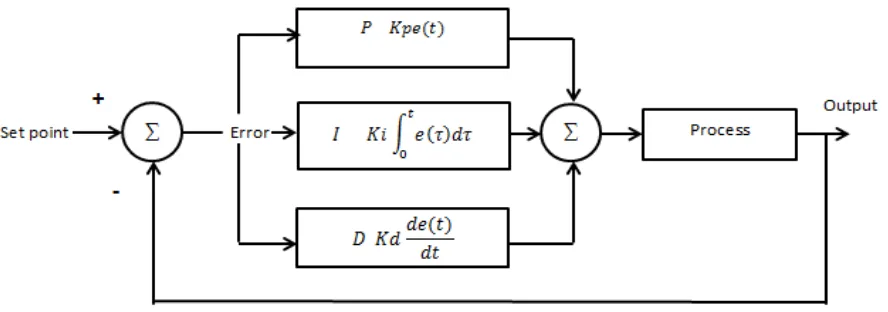
A proportional-integral-derivative controller (PID controller) is a generic feedback controller. A PID controller calculates an "error" value as the difference between a measured process variable and a desired set point. The controller attempts to minimize the error by adjusting the process control inputs [3].
The PID algorithm accounts the following three things are existing error, the time where the system stay away from the mean position and the possible of overshooting the mean position.
The PID controller calculation algorithm involves three separate constant parameters, and is accordingly sometimes called three-term control: the proportional, the integral and derivative values, denoted by terms P, I, and D. Simply put, these values can be interpreted in terms of time. P depends on the present error, I on the accumulation of past errors, and D is a prediction of future errors, based on current rate of changing.
The PID control scheme is named after its three correcting terms, whose sum constitutes the manipulated variable (MV). The final form of PID algorithm is:
( ) ( ) ( ) ∫ ( ) ( ) (2.1)
: Proportional gain, a tuning parameter
: Integral gain, a tuning parameter
8
: Time or instantaneous time (the present)
[image:23.595.92.536.151.307.2]: Variable of integration; takes on values from time 0 to the present .
Figure 2.2: A block diagram of a PID controller in a feedback loop
2.2.1 Proportional term
The proportional term produces an output value that is proportional to the current error value. The proportional response can be adjusted by multiplying the error by a constant Kp,
called the proportional gain constant [3]. The proportional term given:
( ) (2.2)
2.2.2 Integral term
The integral term is proportional to both the magnitude and duration of the error. The integral in PID controller is the sum of the instantaneous error and give the accumulated offset that should have been corrected previously. The accumulated error is then multiplied by the integral gain Ki and added to the controller output [3].
The integral term given:
9
2.2.3 Derivative term
The derivative of the process error is calculated by determining the slope of the error over time and multiplying the rate of change by the derivative gain . The magnitude of the
contribution of the derivative term to the overall control action is termed the derivative gain,
The derivative term given:
![Figure 1.1: Number of accidents, Malaysia, 2005-2009 [1]](https://thumb-us.123doks.com/thumbv2/123dok_us/137030.14174/16.595.95.501.405.620/figure-number-of-accidents-malaysia.webp)
![Figure1.2: Number of traffic and highway accidents, Malaysia, 2004-2008 [1]](https://thumb-us.123doks.com/thumbv2/123dok_us/137030.14174/17.595.96.519.72.348/figure-number-traffic-highway-accidents-malaysia.webp)