UNIVERSITI TEKNIKAL MALAYSIA MELAKA
ANALYSIS OF WHEEL RIM ON THEIR DESIGN AND
STRENGTH
This report submitted in accordance with the requirement of the Universiti Teknikal Malaysia Melaka (UTeM) for the Bachelor’s Degree in Mechanical Engineering
Technology (Automotive Technology) with Honours
by
ALIF IKHSAN BIN KARIM B071110318
921112015327
UNIVERSITI TEKNIKAL MALAYSIA MELAKA
BORANG PENGESAHAN STATUS LAPORAN PROJEK SARJANA MUDA
TAJUK: ANALYSIS OF WHEEL RIM ON THEIR DESIGN AND STRENGTH SESI PENGAJIAN: 2014/15 Semester 2
Saya ALIF IKHSAN BIN KARIM
mengaku membenarkan Laporan PSM ini disimpan di Perpustakaan Universiti Teknikal Malaysia Melaka (UTeM) dengan syarat-syarat kegunaan seperti berikut:
1. Laporan PSM adalah hak milik Universiti Teknikal Malaysia Melaka dan penulis. 2. Perpustakaan Universiti Teknikal Malaysia Melaka dibenarkan membuat salinan
untuk tujuan pengajian sahaja dengan izin penulis.
3. Perpustakaan dibenarkan membuat salinan laporan PSM ini sebagai bahan pertukaran antara institusi pengajian tinggi.
4. **Sila tandakan ( )
SULIT
TERHAD
TIDAK TERHAD
(Mengandungi maklumat yang berdarjah keselamatan atau kepentingan Malaysia sebagaimana yang termaktub dalam AKTA RAHSIA RASMI 1972)
(Mengandungi maklumat TERHAD yang telah ditentukan oleh organisasi/badan di mana penyelidikan dijalankan)
Alamat Tetap:
No 51, Kampung Parit Daun, 86400, Parit Raja, Batu Pahat, Johor.
Tarikh: ________________________
Disahkan oleh:
Cop Rasmi:
Tarikh: _______________________
DECLARATION
"I hereby verify that this report is my own work except the summary and quotation that has been clarified each of the sources"
Signature :
i
APPROVAL
This report is submitted to the Faculty of Engineering Technology of UTeM as a partial fulfillment of the requirements for the degree of Bachelor of Engineering Technology Bachelor Degree of Mechanical Engineering Technology (Automotive) (Hons.). The member of the supervisory is as follow:
ii
ABSTRAK
iii
ABSTRACT
iv
DEDICATION
This report is dedicate for my beloved family who never failed to give me financial and moral support, for giving all my need during the time I developed my system and for teaching me that even the largest task can be accomplished if it done one step at a time.
v
ACKNOWLEDGMENTS
vi
TABLE OF CONTENT
TITLE PAGE
Title i
Declaration ii
Acknowledgement iii
Abstract iv
Abstrak v
Table of Content vi
List of Tables ix
List of Figures x
List of Abbreviations xii
1. INTRODUCTION
1.1 Background 1
1.2 Problem Statement of Study 3
1.3 Objective 4
1.4 Project Scope 4
2. LITERATURE REVIEW
2.1 Types of Wheels 6
2.2 Design of Wheels 8
2.2.1 Pitch Circle Diameter 8
2.2.2 Wheel Offset 11
2.2.3 Size of Wheel 12
2.3 Strength of Wheel 14
vii
2.4.1 Aluminum Alloy Wheel Manufacturing Process 16
2.4.1.1 Casting Process 16
2.4.1.2 Forging Process 18
(a) One Piece Rim 18
(b) Two Piece Rim 20
(c) Three Piece Rim 21
2.4.2 Steel Wheel Manufacturing Process 23
2.5 Composite Materials 24
2.6 Computational Analysis of Wheel 27
2.6.1 Structural Analysis 27
2.6.2 Fatigue Analysis 28
2.6.3 Vibrational Analysis 29
2.6.4 Heat Transfer Analysis 30
2.7 Lab Testing 32
2.7.1 Rolling Testing 32
2.7.2 Fatigue Testing 32
2.7.3 Impact Testing 34
2.7.4 Driving Testing 35
2.8 Failure Theory 35
3. METHODOLOGY
3.1 Overview 37
3.2 Project Flowchart 38
3.3 Existing Design Survey 39
3.4 Modeling of Wheels 40
3.4.1 Modeling Stage 41
3.5 Computational Analysis 43
3.5.1 Preprocessor Stage 44
3.6 Lab Testing 45
viii 4. RESULT AND DISCUSSION
4.1 Generative Structural Analysis By CATIA 50
4.2 Material Properties Of Wheels 52
4.3 Result Of The Analysis 53
4.3.1 Maximum Von Mises Stress With Force Distribution 55
4.4 Actual Test Result 59
4.5 Safety Factor 63
5. CONCLUSION AND FURTHER WORK
5.1 Introduction 64
5.2 Recommendation For Further Work 65
REFERENCES 66
ix
LIST OF TABLES
TITLE PAGE
1.1 Basic comparison of aluminum alloy and steel wheel rim 2
2.1 PCD type of a wheel 9
2.2 Height of rim flanges 11
2.3 Common conversion sizes of wheel and tire 13 2.4 Types of aluminum alloy in general use for casting alloy wheels 23
2.5 Type of material use for manufacturing steel wheel 25 2.6 Comparative static analysis of alloy wheels for different materials 26
3.1 Specifications of model wheel rim 39
3.2 Input data for aluminum 42
3.3 Input data of steel wheel 42
4.1 Material properties of aluminum alloy wheel 52
4.2 Material properties of steel wheel 53
4.3 Maximum Von Mises Stress with force distribution 56
4.4 Wheel deformation with force distribution 59
x
LIST OF FIGURE
TITLE PAGE
1.1 Types of wheel offset 3
2.1 (a) Positive Offset of Wheel 10
2.1 (b) Negative offset of Wheel 10
2.2 SEM topographies of the fatigue fracture surfaces 14
2.2 (a) a typical fracture surface 14
2.2 (b) scratch caused by machining 14
2.2 (c) near surface eutectic Micro constituents 14
2.2 (d) region in the first stage of growth, with typical fatigue striation 14
2.3 Specific procedure of casting process 15
2.4 General procedure of casting process 16
2.5 Forging process in manufacturing one piece rim 18 2.6 Forging process in manufacturing two piece rim 19 2.7 Forging process in manufacturing three piece rim 20
2.8 Part of 3-piece rim 21
2.9 Manufacturing of steel wheel 22
2.10 Meshing of alloy wheel (ANSYS software) 27
2.11 Von Misses stress application on alloy wheel (CATIA software) 27
2.12 Vibration analysis using ANSYS software 29
2.13 Heat transfer analysis using Solidworks software 29
2.14 Wheel rotary fatigue test 31
2.15 Charpy impact test, a) test method and b) notch dimensions 33
2.16 (a) condition of aluminum alloy wheel 34
xi
3.1 Project Flowchart 37
3.2 Aluminum alloy wheel rim (left picture) and steel wheel rim 46 (right picture)
3.3 Measuring diameter of aluminum alloy wheel (left picture) and 46 steel wheel (right picture)
3.4 Measuring width of aluminum alloy wheel (left picture) and steel 47 wheel (right picture)
3.5 Hydraulic press machine 48
3.6 Pressing on the lips of the aluminum alloy wheel (left picture) 48 and zoom of the contact between pressing object and wheel
(right picture)
3.7 Pressing on the lips of the steel wheel (left picture) and zoom 49 of the contact between pressing object and wheel (right picture)
between pressing object and wheel (right picture)
3.8 Deformation on the lips of the wheel (left picture) and the 49 measurement of the wheel deformation (right picture).
4.1 Design of aluminum alloy wheel rim on CATIA drawing 51
4.2 Design of steel wheel rim on CATIA drawing 51
4.3 Translational displacement on aluminum alloy wheel rim 54 (left picture) and steel wheel rim (right picture) with 10000N
of force distribution
4.4 Stress principal on aluminum alloy wheel rim (left picture) and 54 steel wheel rim (right picture) with 10000N of force distribution
4.5 Deformation on aluminum alloy wheel rim (left picture) and steel 55 wheel rim (right picture) with 10000N of force distribution
4.6 Estimated local error on aluminum alloy wheel rim (left picture) 55 and steel wheel rim (right picture) with 10000N of force distribution
xii distribution
4.8 Von Mises Stress on steel wheel rim with 10000N of force distribution 57 4.9 Bar chart of Von Mises Stress on steel wheel rim with 10000N of 58 force distribution
4.10 Aluminum alloy wheel rim before pressing test (left picture) and 61 after pressing test (right picture) of 10000N force distribution
4.11 Steel wheel rim before pressing test (left picture) and after pressing 61 test (right picture) of 10000N force distribution
xiii
LIST OF ABBREVIATIONS
PCD - Pitch Circle Diameter
BCD - Bolt Circle Diameter
SDAS - Secondary Dendrite Arm Spacing
MPa - Mega Pascal
MIG - Metal Inert Gases
FEM - Finite Element Method
FEA - Finite Element Analysis
1
CHAPTER 1
INTRODUCTION
This project introduction includes the explanation of project background, problem statement, objective, and scope of this study.
1.1 Background
2
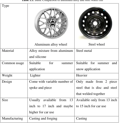
Table 1.1: Basic Comparison of aluminum alloy and steel wheel rim
Type
Aluminum alloy wheel Steel wheel
Material Alloy mixture from aluminum and silicone
Steel metal
Common usage Suitable for summer application
Suitable for summer and snow application
Weight Lighter Heavier
Design Come with variable number of spoke and piece
Only made from 2 piece steel that is disc and steel that welded together
Size Usually available from 13 inch to 17 inch and maybe higher for car use
Available only from 13 inch to 15 inch for car use
Manufacturing Casting and forging Casting
3
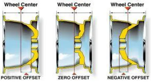
Figure 1.1: Types of wheel offset
Next criteria is the wheel size of the sport rim that shows the distance from the hub-mounting and usually wheel size is depend on the size of the car used while PCD is the diameter of a circle drawn through the center of your wheel’s bolt holes and wheel spoke consisting of a radial member of a wheel joining the hub to the rim. Currently, car manufacturers use different stud or bolt hole patterns for the fitment of their wheels and these must line up exactly with a new ones enabling them to seat properly against the hub.
1.2 Problem Statement of Study
4
Other than that, extensive aftermarket wheel size and offset that easily fit to the cars by customers is dangerous to the stability and control of the car. Wider wheel can increase the load on the wheel shaft that affect the shaft to bend and crack easily. This situation can be worse when the driver lost control of the car and involve in car accident. This example has shown enough that there is no proper guideline for car user and extensive variety of wheels rim available on market makes it an overwhelming experience for users to choose the right ones they need for their car. For this research, we are focusing on the strength analysis of both aluminum alloy and steel rim to find which is more durable and creates a long lasting life for daily usage.
1.3 Objective
To come out with analysis data (comparative) on aluminum alloy versus steel rim and to analyze the strength of both wheel rim by using simulation in CATIA software.
1.4 Project Scope
5
6
CHAPTER 2
LITERATURE REVIEW
2.1 Types of Wheels
A wheel rim is an important part of each car .Depending on the material used in the production of wheel rims, there are some types of common wheel rims available in the automobile market that is aluminum alloy and steel rims. Wheel rim is the outer circular design of the metal on which the inside edge of the tire is mounted on vehicles such as automobiles and types of rims include wire spoke, steel disc, light alloy and aluminum alloy, magnesium alloy wheel, titanium alloy wheel, and composite material wheel. Alloy wheels are now standard on most cars because they offer both cosmetic and performance advantages. Alloys tend to bend more easily than steel under the effect of the road, and have a tendency to crack if bent too far. To the degree that the alloy wheels are soft or brittle depends on how much nickel is added to aluminum to make the alloy more brittle, less light means a softer wheel and tend to bend more easily .Construction methods such as casting or forging pressure also has an effect on the strength of this alloy. Alloy wheels can be polished, painted, machined or chrome that is different finishes should be treated in different ways. They are also exposed to a variety of cosmetic damage such as scrapes the curb, saltwater corrosion and acid cleaners.
7
Large earth-moving vehicles such as the more gigantic dump trucks often have some degree of the vehicle’s suspension actually built into the wheel itself, lying in the middle of the hub and rim in place of spokes. Similarly, many companies make wheels which are designed like steel wheels but are made of aluminum. The design is actually called the center line wheel and the most famous of these are made by centerline.
They used to be made of magnesium for their light weight and strength, but magnesium catches fire somewhat easily and is very difficult to put out. This is unfortunate, because it is superior to aluminum in every other way. This tendency also makes it a dangerous metal to work with, because piles of shavings tend to burst into flame and burn through concrete surfaces when they get too hot.1
Steel wheels are heavier than aluminum, and when you put steel wheels on the car, you tend to find that extra weight dampened acceleration and agility , decrease the center of gravity of the car and in general make it drive more like a tank. Obviously this can be unwanted for application of summer performance, but in winter the effect can be a physical and psychological advantage significantly. Heavier wheels will make snow tires bite harder, and when driving in the snow, having a car with sluggish acceleration and agility, low center of gravity and make sense of toughness and weight can be a very good thing. Steel wheels are stronger than alloy wheels and it takes more force to bend the steel wheels and it is difficult to crack them. Given their functional looks familiar, purely cosmetic damage is not usually a big issue.
8
brake calipers or other suspension issues. Steels are also usually 75-80% less expensive than alloy wheels, making them great for a second set, and inexpensive to replace if badly damaged. Thus for many reasons alloys are the only choice when high performance and/or looks are the qualities you need. Steels are generally better for those no-nonsense daily drivers, or for any cars that don't have to look pretty or do fancy maneuvers because they work for a living. They are especially ideal, however for that extra set of winter wheels. 2
2.2 Design of Wheel
2.2.1 Pitch Circle Diameter (PCD)