i
A STUDY OF FIN IN ARRAYS AS A HEAT SINK OF MOTORCYCLE THERMOELECTRIC POWER GENERATOR (MTEG)
MOHD FAISAL BIN HARUN
This report presented to fulfill the requirement in order to be awarded with
Bachelor of Degree in Mechanical Engineering (Thermal-Fluid)
Faculty of Mechanical Engineering
Universiti Teknikal Malaysia Melaka
ii
SUPERVISOR’S VERIFICATION
I hereby admit that have read this report and from my point of view this report is enough in term of scope and quality for purpose for awarding
Bachelor of Degree in Mechanical Engineering (Thermal-Fluid)
iii
DECLARATION
“I admit this report has been written by me myself except for some equation that has been noted well for each of them”
iv
DEDICATION
v
ACKNOWLEDGEMENT
First and foremost, ALHAMDULILLAH I'm grateful to ALLAH SWT on blessing in completing this project.
I would like to take this opportunity to thank my project supervisor , Mr. Mohamad Firdaus bin Sukri for invaluable guidance, assistance and support throughout this work. Under his supervision, many aspects regarding on this project has been explored and with knowledge, idea and support received from him, this report can be represented in the given time.
vi
ABSTRACT
vii
ABSTRAK
viii
TABLE OF CONTENT
TITLE PAGE
SUPERVISOR’S VERIFICATION ii
DECLARATION iii
DEDICATION iv
ACKNOWLEDGEMENT v
ABSTRACT vi
ABSTRAK vii
TABLE OF CONTENT viii
LIST OF FIGURE xi
LIST OF TABLE xiii
LIST OF SYMBOL xiv
LIST OF APPENDIX xv
CHAPTER 1 1
INTRODUCTION 1
1.1 Background 1
1.2 Problem Statement 2
1.3 Objective 2
ix
CHAPTER 2 3
LITERITURE RIVIEW 3
2.1 Introduction 3
2.2 Heat Transfer 5
2.3 Convection 8
2.4 Thermal Conductivity 10
2.5 Fin Performance 19
2.6 Overall Efficiency 24
2.7 Fin Analysis 26
CHAPTER 3 29
METHADOLOGY 29
3.1 Introduction 29
3.1 Flow Chart 30
3.2 Theoretical Analysis 31
CHAPTER 4 35
RESLUTS AND DISCUSSION 35
4.1 Introduction 35
4.2 Fin Analysis 35
4.3 Result 38
4.4 Data Analysis 41
4.5 Fin Analysis 44
CHAPTER 5 45
CONCLUSION & RECOMMENDATION 45
5.1 Conclusion 45
x
REFERENCES 47
APPENDIX A 49
APPENDIX B 51
xi
LIST OF FIGURE
NO TITLE PAGE
Figure 2.1 One dimensional heat transfer by conduction 6
Figure 2.2 Boundary layer development in convection heat transfer 9
Figure 2.3 Range of thermal conductivity for various state of matter 13 at normal temperature and pressure
Figure 2.4 Temperature dependence of the thermal conductivity 15 of selected solids
Figure 2.5 Variation of thermal conductivity with temperature for 15 various metal
Figure 2.6 The temperature dependence of the thermal conductivity 17 of selected gases at normal pressure
Figure 2.7 Variation of thermal conductivity with temperature for 17 various gases
[image:11.612.127.530.222.702.2]Figure 2.8 The temperature dependence of the thermal conductivity 18 of selected nonmetallic liquid under saturated conditions
xii
Figure 2.10 Efficiency of straight fin of rectangular, triangular, and 22
parabolic profile Figure 2.11 Efficiency of annular fins of rectangular profile 22
Figure 2.12 Fin array of annular fin 24
Figure 2.13 Overall view of the experimental rig and associated instrument 28
Figure 3.1 Methodology flow chart 30
Figure 3.2 Variable parameter of fin in 2D 31
Figure 3.4 Variable parameter of fin in 3D 32
Figure 4.1 Graph overall efficiency vs convection coefficient 41
xiii
LIST OF TABLE
[image:13.612.131.508.108.675.2]NO TITLE PAGE
Table 2.1 Typical value of the convection heat transfer 10
coefficient Table 2.2 Thermal conductivity of various material at 0°C 12
Table 3.1 Variable value for case 1 33
Table 3.2 Variable value for case 2 33
Table 3.3 Variable value for case 3 34
Table 3.4 Variable value for case 4 34
Table 4.1 Analysis fin efficiency: h = 25W/m2.K 38
Table 4.2 Analysis fin efficiency: h = 75W/m2.K 39
Table 4.3 Analysis fin efficiency: h = 125W/m2.K 39
Table 4.4 Analysis fin efficiency: h = 200W/m2.K 40
xiv
LIST OF SYMBOL
k = thermal conductivity (W/m.k)
= fin effectiveness = effectiveness
, = fin thermal resistance (K/W) , = fin contact resistance (K/W)
= heat transfer rate for convection (W/m) = area of fin
= fin profile area (m2) = thermal capacitance ( J/K) = volume (m3)
= area base plate (m2) = area of prime surface (m2) = number of fins
= total heat transfer rate by convection) (W/m) s = pitch diameter
d2 = tip diameter fin
d1 = diameter of fin
xv
LIST OF APPENDIX
TITLE PAGE
APPENDIX A
Gant chart PSM 1 49
Gant Chart PSM 2 51
APPENDIX B
Efficiency of common fin shape 51
APPENDIX C
1
CHAPTER 1
INTRODUCTION
1.1 Background
Heat sink such as annular fin heat sink has been used widely today such as in radiator and internal heat exchanger in domestic applications such as radiator in rooms, condensing central heating exchanger, air conditioning equipment for the basic element of heating, cooling, conditioning and internal and external surfaces in refrigeration unit, electronics board such as computer processor cooling units and other electronics chips.
Lot of operations engineering system producing heat and some product will facing a big problem when the product is overheating that also can make failure to the system. In order to maintain the system operate at its suitable working temperature and function effectively, the heat from the system must be release to the surrounding and heat sink will be needed in order to got more effectiveness heat release.
2
1.2 Problem Statement
The primary goal in heat sink design is to increase the heat transfer rate while decreasing the momentum resistance. Based on this objective, determine the highest efficiency of the heat sink on the maximum allowable size of fins that already given. This theoretical analysis is to determine the best efficiency at allowable maximum size of fin. Previous study shown that the maximum allowable size of heat sink for MTEG application is 0.18 m x 0.098 m x 0.02 m and to determine the best efficiency of annular heat sink with maximum allowable size of 0.18 m x 0.098 m x 0.02 m in term of fin thickness, pitch and the number of fin. However the efficiency of the fin also influence by the thermal conductivity material of the fin. The thermal conductivity is depending on the material that been used to manufactured the fin. There are several type of the material that commonly used in the industrial such as silver, copper, aluminium, copper and vice versa
1.3 Objective
To investigate the effect of annular fin's thickness and pitch to the overall surface efficiency of the heat sink
1.4 Scope
The scope of this study are as follows
1. Literature review on related topics.
2. Theoretical analysis on the performance of the heat sink.
3. Cross sectional area of annular fin with maximum allowable size. 4. Case of finite fin with convective heat transfer made at the tip of the fin. 5. Fixed material for fin.
3
CHAPTER 2
LITERITURE RIVIEW
2.1 Introduction
Annular fin based heat sink that been used in heat transfer process usually related to the fins radius, cross sectional area and the thermal conductivity of the material to obtaining the high efficiency values. The purpose of fin annulus is to increase the contact surface area thus increase the value of convection heat transfer between the object and surrounding area.
In general, there are several type of the fin that commonly used in the industrial such as straight rectangular fins, straight triangular fins, straight parabolic fins, circular fin of rectangular profile, pin fins of rectangular profile, pin fins of triangular profile, pin fins of parabolic profile, and pin fin of parabolic profile (blunt tip). Fin design usually made to minimize the fin material or the manufacturing costs that required achieving the cooling effectiveness that already been set (Incropera 2007).
4
suitable for applications that require minimum weight, such as application in outer space (Rathore 2011).
The efficiency of the fin will decrease when the length of the fin is increase. In this regard, heat dissipation per unit volume is largest for a parabolic Profile and slightly larger than triangular profile and it rarely used because it takes greater manufacturing costs compared to the other fin. Usually the annular fin of rectangular profile is commonly used to increase the heat transfer rate. The efficiency of most fins that used in industrial is above 90% (Cengel 2006).
The heat transfer rate may be increase by increasing the surface area across the convection occurs. This can be done by using fins that extend from the wall into the surrounding fluid. Thermal conductivity of the fin can influence the temperature distribution along the fin and it also can increase the heat transfer rate for the fin. The higher the value of thermal conductivity the higher the transfer. Preferably, the material of the fin should have the larger thermal conductivity to minimize the temperature variations form the bas to the tip. The other example of fin application is the arrangement for cooling engine heads an motorcycles and lawn mowers or for the cooling electric power transformer (Incropera 2007).
Fin efficiency is the parameter that makes a higher thermal conductivity material of fin is important. A fin of a heat sink may be considered to be a flat plate with heat flowing in one end and being disappear into the surrounding as it moves to the other side. As heat flows through the fins, the thermal resistance of the heat sink prevents the flow and the heat lost causes by convection, the temperature of the fin and, because of that, the heat transfer to the fluid, will decrease from the base to the tip of the fin. This is called the fin efficiency and is defined as the actual heat transferred by the fin and divided by the heat transfer were the fin to be isothermal(Incropera 2007).
5
2.2 Heat Transfer
Heat is the thermal form of energy and it has been proclaimed by the well known conservative law " energy can never be created or destroyed". This make possible to consider the conversion of one form energy to other. The different branches of science and technology deal with the conversion of different of form energy. For example electrical sciences deal with conversion of electrical energy to other forms and vice versa, chemical science deal with chemical energy conversion and so on (Das 2010). Heat transfer is the transmission of energy form one region to another region as a result of the temperature difference between them. Whenever there is exist temperature difference in media or within a medium, heat transfer must occur. When a temperature gradient exist in a medium which may solid, fluid or gas then the heat transfer occur is called conduction. In contrast, convection refers to the heat transfer that will occur between a surface and a moving medium when they are at different temperature. The third mode of heat transfer is thermal radiation. All surface at a finite temperature emit energy in the form of electromagnetic waves. Thermal radiation can also occur in the absence of any medium (Rathore 2011).
2.2.1 Conduction
6
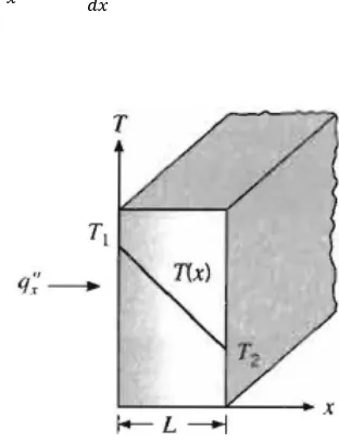
These equation used to compute the amount of energy being transfer per unit time. For heat conduction, the rate equation is known as Fourier's Law. For one dimensional plane wall shown in figure 2.1, having a temperature distribution T(x), the rate equation is (Incropera 2007)
[image:21.612.247.403.178.382.2]" =− (Eqn 2.1)
Figure 2.1 : One dimensional heat transfer by conduction (diffusion energy) (source : Incropera, (2005))
The heat flux " (W/m2) is the heat transfer rate in the x direction per unit area perpendicular to the direction of transfer and it proportional to the temperature gradient, / , in this condition. The proportional constant k is a transport property known as thermal conductivity and is a characteristic of the wall material. Under the steady-state conditions, the temperature distribution is linear, the temperature gradient expressed as
= (Eqn 2.2)
and the heat flux is
7
Or described by
" =− = ∆ (Eqn 2.4)
2.2.2 Radiation
Thermal radiation is energy emitted by matter is that is at finite temperature. The emission may be attributed to changes in the electron configuration of the constituent atoms or molecules. The energy of the radiation is transport by electromagnetic waves(or alternatively, photons). Radiation that is emitted by the surface originates from the thermal energy of matter bounded by the surface., and the rate at which energy is released per unit area (W/m2) is termed the surface emissive power E. There is the upper limit to the emissive power, which is prescribed by the Stefan-Boltzmann Law
= (Eqn 2.5)
where T is absolute temperature (K) of the surface and σ is the Stefan-Boltzmann constant (σ=5.67 x 10⁻⁸W/m2.K4). The net rate of radiation heat transfer from the surface, expressed per unit area of the surface is
" = = ( )− = ( − ) (Eqn 2.6)
this expression provides the difference between the thermal energy that is released due to radiation emission and that which is gained due radiation absorption. There are application for which it is convenient to express the net radiation heat exchanger in the form
8
where radiation heat transfer coefficient ht is
ℎ = ( + )( + ) (Eqn 2.8)
In this sense linearized the radiation rate equation, making the rate proportional to a temperature different rather than to the differences between two temperatures to the fourth power. However, that ht depends strongly on temperature, while the temperature dependence of the convection heat transfer coefficient h i generally weak. The total rate of heat transfer from the surface is
= + =ℎ ( − ) + ( − ) (Eqn 2.9)
2.3 Convection
Convection heat transfer mode is comprised of two mechanisms. In addition to energy transfer due to random molecule motion (diffuser), energy is also transferred by the bulk, or macroscopic, motion of the fluid. This fluid motion is associated with the fact that, at any instant, large number of molecules are moving collectively or as aggregates. Because the molecule in the aggregate retain their random motion, the total heat transfer is due to a superposition of energy transport by the random motion of the molecules and by the bulk motion of the fluid.
9
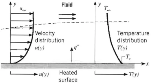
Figure 2.2 : Boundary layer development in convection heat transfer (source : Incropera, (2005))
Regardless of particular nature of convection coefficient heat transfer process, the appropriate rate equation is form
" =ℎ( − ) (Eqn 2.10)
Where q", the convective heat flux (W/m2), is proportional to the difference between the surface and fluids temperature, and , respectively. This expression known as Newton's Law of cooling, and the proportionally constant h(W/m2.K) is termed the convection heat transfer coefficient. It depend on conditions in the boundary layer, which are influenced by surface geometry, the nature of the fluid motion, and assortment of fluid thermodynamics and transport properties. Any study of convection ultimately reduces to a study of the mean by which h may be determined. In the solution of such problems h to be known suing typical value in the table 2.1. The equation 2.11 used for convection of heat flux is presumed to be positive if heat is transferred from the surface ( > ) and negative if heat is transfer to the surface ( > ). However, if > , there is to preclude from expressing Newton's law of cooling as