PJP/2007/FKEK.K (5) S276
DYNAMIC-INVERSION-BASED CONTROL FOR VIBRATION-FREE POSITIONING OF A GANTRY CRANE SYSTEM
AZDIANA BINTI MD. YUSOP NOOR ASYIKIN BINTI SULAIMAN SHARA TUL IZAH BINTI SAM SUD IN
MOHD SHAKIR BIN MD SAAT
RESEARCH VOTE NO: PJP/2007/FKEKK (5) S276
Fakulti Kejuruteraan Elektronik dan Kejuruteraan Komputer Universiti Teknikal Malaysia Melaka
"I hereby declare that this report is the result of my own work except for quotes as cited in the references."
Signature Author Date
:
..
~·
..
... .
ii
ACKNOWLEDGEMENT
First and foremost, I would like to thank Allah for His blessing. He gave me
physical and mental strength to carry this research up to completion. I take this
opportunity to express my profoundest gratitude and deepest regards to all those who
gave me the possibility to successfully complete this research. I wish to express a million
thanks to UNIC and FKEKK for the financial support, exemplary guidance, monitoring
and constant encouragement throughout the development of the research.
I wish to express my sincere gratitude and appreciation to all my co-researchers
for their helpful suggestions in developing this project, for their support and
encouragement to me. Last but not least, to all my well-wishers who had helped me both
directly and indirectly, I virtually fall to short words to express my gratitude. Therefore, I
DYNAMIC-INVERSION-BASED CONTROL FOR VIBRATION-FREE POSITIONING OF A GANTRY CRANE SYSTEM
(Keywords: Input shaping, Inverse dynamic analysis, gantry crane system)
iii
The inverse dynamic analysis is a simple method that is used for reducing the vibration and the sway angle for the gantry crane system. The shaped input function is derived from the specified output function. Third order exponential function is used as the desired output due to its asymptotic behavior. The simulation has been done to the gantry crane system which is fourth order system by using feedback control. In the proposed method the parameters that need to be defmed is the position of the trolley and the sway angle of the mass. Simulated responses of the position of trolley and sway angle of the mass are presented using MA TLAB. From the simulation results, satisfactory vibration reduction of a gantry crane system has been achieved using the proposed method.
Key Researchers:
Azdiana binti Md. Yusop Noor Asyikin binti Sulaiman Sharatul Izah binti Samsudin Mohd. Shakir bin Md Saat
E-mail :[email protected] Tel. No.: 06-5552044
iv
CONTENTS
CHAPTER TITLE PAGE
DECLARATION i
ACKNOWLEDGEMENT ii
ABSTRACT iii
CONTENTS iv
LIST OF TABLES viii
LIST OF FIGURES ix
LIST OF SYMBOLS xii
LIST ABBREVIATIONS X Ill
LIST OF APPENDIXS xiv
I PROJECT INTRODUCTION
1.1 Introduction 1
1.2 Objective 3
1.3 Problem Statement 3
1.4 Research Methodology 4
v
IT LITERATURE REVIEW
2.1 Input Shaping Techniques 9
2.1.1 Posicast-based Control 11
2.1.2 Unity Magnitude Zero Vibration Shaper
UMZV) 12
2.1.3 Specified-Negative-Amplitude shaper
(SNA) 12
2.1.4 Dynamic Inversion Based Control Method 13
2.2 Background of a Gantry Crane 13
2.3 Motion Control System 17
2.3.1 Stepper Motor 17
2.3 .1.1 Operation Principle of Stepper Motor 19
2.3.2 Servo Motor 20
2.3.3 Comparison between the Servo Motor
and Stepper Motor 20
2.4 Microcontroller 22
2.4.1 Overview Microchip PIC 24
2.5 Data Acquisition Board (DAQ) 25
2.6 SCC-68 26
III MATHEMATICAL MODELING
3.1 Nonlinear Feedback Control of a Gantry Crane 28
3.2 Desired Motion 29
3.3 Modeling of the Gantry Crane 31
3.4 Derivation of the Equations ofMotion 32
vi
IV INVERSE DYNAMIC ANALYSIS
4.1 Dynamic Inversion Based Control 37
V RESEARCH METHODOLOGY
5.1 Introduction 40
5.2 Hardware Development 41
5.2.1 Microcontroller 43
5.2.1.1 Pin description 44
5.2.1.2 Microcontroller Schematic 46
5.2.2 L293D Motor driver IC 48
5.2.2.1 Motor Driver Schematic 48
5.2.2.2 Rotation for Stepper Motor
and Trolley Wheel 51
5.2.3 Power Supply 52
5.2.4 AutoCAD 53
5.2.4.1 Gantry Crane Layout in 2D 54
5.2.4.2 Gantry Crane Layout in 3D 58
5.3 Software Development 59
5.3.1 Simulink IMA TLAB Design Flow Chart 59
5.3.1.1 MATLAB 60
5.3.1.2 SIMULINK 63
5.3.2 Software development for Microcontroller 66
5.3.2.1 Flow Chart for Basic Programming
Language 66
5.3.2.2 MPLAB 67
5.3.2.3 BASIC Language 68
VI ANALYSIS AND RESULT
6.1 SIMULINK Model of the Gantry Crane
System in 4th Order System
6.1.1 General Model
6.1.2 Comparison between Open Loop and
Closed Loop System
6.1.3 Input Force
6.1.4 Position of the Trolley
6.1.5 Sway Angle
6.2 The Schematic of Manual Control System
6.2.1 PCB Layout Design
6.3 The Manual Control of Gantry Crane Layout in 3D
6.3.1 Manually control ofthe Gantry Crane
Model
6.4 Automatic control of the Gantry Crane layout in 3D
VII CONCLUSION AND FUTURE WORKS
7.1 Conclusion
7.2 Future Works
viii
LIST OF TABLES
NO
TITLE PAGE2.1 Comparison between servo motor and stepper motor 20
2.2 Difference types of microcontrollers 23
5.1 Pins for PIC 16F84A micro controller and its function 45
5.2 Connection of pins PIC 16F84A with other components 46
5.3 The connection of pins IC L293D and its function 49
5.4 Categories of MA TLAB works 61
5.5 Simulink categories 63
5.6 Simulink products 64
5.7 The description for the debug icon 67
5.9 MicroPro icon 69
6.1 Summary result of open loop system and closed loop system
ix
LIST OF FIGURES
NO TITLE PAGE
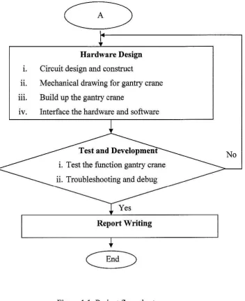
1.1 Project flow chart 6
2.1 Destructive interference 10
2.2 Input shaping process 10
2.3 Posicast control 11
2.4 SNA shaper sensitivity plots 12
2.5 Fixed height steel gantry crane 14
2.6 Pillar and wall-mounted slewing jib cranes 15
2.7 Super-post panamax portainer crane 15
2.8 Double girder crane 16
2.9 Operation of a stepper motor 19
2.10 Microcontroller-based system 22
2.11 Some of the various PICs from Microchip 24
2.12 Insert the DAQ card into the PC 26
2.13 SCC-68 parts locator diagram 26
2.14 SCC-68 power distribution block diagram 27
3.1 Model of a gantry crane 31
5.1 Manual control of gantry crane system 41
5.2 Automatic control of gantry crane system 42
5.3 PIC16F84A block diagram 44
X
5.5 Microcontroller schematic 46
5.6 IC L293D 48
5.7 Motor driver schematic 49
5.8 Stepper motor and run wheel diagram 51
5.9 Block diagram of 5V power supply to microcontroller and
motor drive 52
5.10 Power supply circuit 52
5.11 Example of AutoCAD drawing 53
5.12 Layer properties manager 54
5.13 Trolley layout in 2D 55
5.14 The front view of the gantry crane in 2D 56
5.15 The top view of the gantry crane in 2D 57
5.16 The side view ofthe gantry crane in 2D 57
5.17 The front view of the gantry crane in 3D 58
5.18 MA TLAB software design flow chart 59
5.19 Default appearance of the desktop 61
5.20 Simulink library 64
5.21 Simulink library brower for real-time workshop 65
5.22 Flow chart for basic programming language 66
5.23 An icon for the debugging is added to the icon bar 67
5.24 The equipment used for program the IC 69
6.1 Label the parameters at block mask editor 72
6.2 Block parameter for fen 72
6.3 Block parameter for workspace 73
6.4 Block Parameter for inverse dynamic 73
6.5 Open loop system for nonlinear model 74
6.6 Closed loop system for method 1 75
6.7 Closed loop system for method 2 75
6.8 Closed loop system for method 3 76
6.9 Input force 79
xi
6.11
Sway angle81
6.12
Schematic of manual control system81
6.13
PCB layout85
6.14
The top view of PCB with components85
6.15
Front view and top view of the manual control of gantrycrane system in 3D
86
6.16
Side view of the manual control of gantry crane system in 3D87
6
.
17
The trolley layout in 3D88
6.18
Lab-scale gantry crane model89
6.19
The front view for automatic control of the gantry crane system90
6.20
The back view for automatic control of the gantry crane system91
6.21
The top view for automatic control of the gantry crane system91
6.22
The side view for automatic control of the gantry crane system92
7.1
NCTF control system95
xu
LIST OF SYMBOLS
M -Trolley mass
m -Payload mass
l -Length of the hoisting rope
F -Input force X
-2 G -Gravitational acceleration= 9.8lms
G -Centre point
s
-Point of suspensionX -Trolley position
X -Velocity
x
- AccelerationB -Sway angle
e
- Angular velocityAID
CPU
DIA
DAQ DC EEPROM EIA FFT 1/0 MCU NI PIC RAM RTW RS ROM SNA UMZV xiii
LIST OF ABBREVIATIONS
- Analog-to-digital
-Central Processing Unit
- Digital-to-Analog
- Data Acquisition Board
- Direct Current
-Electrically Erasable Programmable Read Only Memory
- Electronic Industries Alliance
-Fast Fourier Transform
- Input I Output
-Microchip Microcontroller
-National Instruments
- Peripheral Interface Controller
- Random-Access Memory
- Real Time Workshop
- Recommended Standard
- Read-only Memory
-Specified Negative Amplitude shaper
xiv
LIST OF APPENDIXS
NO
TITLE PAGECHAPTER I
PROJECT INTRODUCTION
This chapter will emphasize on the gantry crane system with dynamic
inversion based control. The project introduction, project objective, problem
statement, and scopes of work, methodology and thesis outline will also be presented.
1.1 Introduction
A gantry crane system is a crane carrying the trolley or trolley with a movable
or fixed hoisting mechanism, that the bridge is rigidly supported on two or more legs
running on fixed rails or other runway. The fundamental motions of a gantry crane
consist of traversing, load hosting and load lowering. Gantry cranes are widely used
as an efficient means of traversing heavy object in factories, warehouse and shipping
yards. Like other crane types, gantry cranes met with some dissatisfactory due to its
natural characteristics.
As mentioned, the fundamental motions of a gantry crane consist of traversing,
load hosting and load lowering. These significant characteristic is that all motions are
performed simultaneous at relatively high speed. Crane traversing motions,
particularly when starting or stopping; induce undesirable swinging of the suspended
2
leave its groove which could lead to over wrappmg and damage. One of the
characteristics of these cranes is the flexible hoisting ropes used as a part of the
structure for the reduction of system mass, which result in favorable features of high
payload ratio, high motion speed and low power consumption. However, the flexible
hoisting create serious problems, that is the crane acceleration which required for
motion will generate undesirable load swing, which is frequently aggravated by load
hoisting. Therefore, such load swing should be suppressed as rapidly as possible to
maximize the operations.
Several methods of open-loop and closed-loop solutions have been proposed
in order to control the vibration. For example, open loop time optimal strategies were
applied to the crane by many researchers such as discussed in [1, 2]. They came out
with poor results because open loop strategy is sensitive to the system parameters (e.g.
rope length) and could not compensate for wind disturbances [3]. The most popular
technique for input shaping is to convolve a sequence of impulses and various
methods for shaping impulse sequence of impulses have been testified and applied to
crane system as in [4]. M N Sahinkaya in his paper [5] also has reported the same
inverse dynamic technique in spring-mass-damper system. However all the above
method is still an open-loop approach that avoid the system from become less
sensitive to disturbances.
Increasingly however, feedback control which is well known to be less
sensitive to disturbances and parameter variations also adopted to control the gantry
crane system. Work that has been presented by Omar [ 6] had proposed PD
(Proportional-Derivative) controllers for both position and anti-swing controls.
Moreover, a Fuzzy Logic Controller had been introduced by Wahyudi and Jamaludin
[3]. Fuzzy logic controllers were designed and implemented for controlling payload
position as well as the swing angle of the gantry crane. In this paper, robustness of the
proposed intelligent gantry crane system is evaluated and compared with an automatic
gantry crane controlled by the classical PID (Proportional-Integral- Derivatives)
controllers. The result shows that the intelligent gantry crane system has a better
performance and more robust to parameter variation compared to the automatic crane
3
However, most of the open loop and feedback methods start with a parametric
input function, which usually involves magnitude and time delay. By using the
inverse dynamic analysis with a feedback control, the designer can choose the speed
and shape of the motion within the limitations of the drive system and can ensure that
the system is less sensitive to disturbances and parameter variations.
This research will focus on a feedback control system based on the dynamic
model of the gantry crane system. The main idea is to produce vibration free system
using inverse dynamic analysis.
1.2 Objective
This research is attempts to:
1. specify an input function that will drive the system from an initial position into
a target position as fast as possible without vibration at the target position and
within the physical constraints of the drive system.
11. build the gantry-crane system model.
111. control the crane using the inverse dynamic analysis by interfacing the input
function to the real system.
1v. patent this product and promote to the other higher education institute as to
generate income to the University.
1.3 Problem Statement
The safety and efficiency of the operation of a gantry crane are generally
reduced by the transient sway and residual oscillation of either the empty hook or the
payload. In general, this problem is tackled by the experience and skill of the
operators, who try to impose a deceleration law that reduces the oscillation caused by
the acceleration. Moreover, a man is often tasked to stop the hook or the payload.
Thus, the performances of the system can be significantly improved by using
appropriate automatic control architecture, which is capable of reducing the swing
4
However, the design of the controller is a challenging problem, since the system, which can be regarded as a single-pendulum, is nonlinear (and hence, if a linearised model is considered for the controller design, then the attained performances have to be verified against a complete nonlinear model) and the value of certain system parameters such as the rope length and the payload mass may
significantly vary during the operations. Moreover, in the minimization of the motion
time of the payload the trolley driving motor constraints have to be taken into account.
In this research project, the way of deriving the inverse dynamic input must be studied first. Then the actual system of a gantry-crane system must be built. The last problem that should be considered is the interfacing between the controllers and the actual system which is one of the critical parts in this project.
1.4 Research Methodology
At the first stage, the mathematical model of a gantry-crane system must be derived. It is important in order to test the input function effectiveness before interfacing to the actual system. Since the system is nonlinear, thus, it is being linearized by using some assumptions to eliminate some nonlinearities of the system.
Then, the shaped input function will be derived from the specified output function, in this case is a third order exponential function. After completing the deriving process, the input function will be applied into the open loop and closed loop gantry-crane system. The dynamic model will be developed using MATLAB and SIMULINK.
5
load hoisting. Therefore, such load swing should be suppressed as rapidly as possible
to maximize the operations.
The final stage of this research project is to interface the input function (designing
in the PC) to the actual gantry-crane system (hardware). At this point, the controller is
performed to control the actual gantry-crane system. The performance comparison of
the simulation and experimental will be carried out and minor modification should be
Literature Review
Modeling of gantry crane
1. Derivation the motion equations
11. Inverse dynamic analysis
Inverse dynamic Analysis in MA TLAB
1. Develop the nonlinear crane model using
MATLAB and SIMULINK
Apply the inverse dynamic method into the nonlinear crane modal for close loop
Design coding for microcontroller
1. Write the basic language coding by using PIC basic software 11. Generate basic language to the HEX file by MPlab
iii. The PIC programmer is use to burn the Hex file into the PIC 16F84
7
Hardware Design
1. Circuit design and construct
n. Mechanical drawing for gantry crane
m. Build up the gantry crane
tv. Interface the hardware and software
No
[image:22.536.114.467.51.484.2]Report Writing
8
1.5 Report Structure
This report is a documentary to deliver the generated idea, the concepts
applied, the activities done, and the product produced. The report consists of seven
chapters.
Chapter I is about some background of the project. Furthermore, the objective
of project, problem statement, methodology and report outline also will be presented.
Chapter II contain literature review about the precise position control, rapid
rest-to-rest motion and the several techniques of input shaping that will reduce the
vibration for the gantry crane. On the other hand, this chapter also will clarify the way
to choose the suitable motor and PIC microcontroller.
Chapter III will include the derivation of equations of motion for a gantry
carne. On the other hand, this chapter will explain more about the equation of motion
and represents it in the time domain.
Chapter IV will illustrate the inversion dynamic based control method. This
method will reverse the process by specifying the system output function and deriving
the input.
In Chapter V contain the methodology for hardware and software. The design
flow and construction of the project is introduced. It gives brief description about
each procedure in completing the project. This chapter includes a list of tools and
approaches used in the project.
Chapter VI will cover the result, analysis and discussion. On the other hand,
this chapter will include the result and analysis for the manual control gantry crane.
Finally, Chapter VII is the conclusion of this research. It also contains the
application of the project and the recommendation that can be implemented in the
CHAPTER II
LITERATURE REVIEW
Literature review is done in this chapter to make a review of the several
techniques of input shaping that will reduce the vibration. This chapter also will
clarify the way to choose the suitable motor, PIC microcontroller, Data Acquisition
Board (DAQ Card) and signal conditioning circuit.
2.1 Input Shaping Techniques
Input shaping is a simple and effective method for reducing the residual
vibration when position lightly damped system. One very useful form of command
shaping is input shaping. Input shaping is applicable in real time, and input shapers
can be designed to have any desirable robustness level. Input shaping is designed to
reduce, or eliminate, command-induced system vibration [9]. A desired reference
command given to a flexible system will, in general, result in residual vibration.
Input shaping is ability to cancel vibration can be viewed as destructive interference
of sinusoidal waves [10]. If two sinusoids of the same magnitude, same frequency and
correct phase shift between them are added together, the resulting combination will