DEVELOPMENT OF A PI SPEED CONTROLLER FOR DC MOTOR DRIVE USING RABBIT MICROPROCESSOR
LEONG CHEE MENG
―I hereby declared that I have read through this report and found that
it has comply the partial fulfilment for awarding the degree of
Bachelor of Electrical Engineering (Power Electronic and Drive)‖
Signature
: ………
…
Supervisor‘s Name
: ………
…
Date
: ………
DEVELOPMENT OF A PI SPEED CONTROLLER FOR DC
MOTOR DRIVE USING RABBIT MICROPROCESSOR
LEONG CHEE MENG
This Report Is Submitted In Partial Fulfilment of Requirement for the
Degree of Bachelor in Electrical Engineering (Power Electronic and
Drive)
Fakulti Kejuruteraan Elektrik
Universiti Teknikal Malaysia Melaka
―I hereby declared that this report is a result of my own work except
for the excerpts that have been cited clearly in the references.‖
Signature
: ……… …
Name
: ……… …
Date
ACKNOWLEDGEMENT
First of all, I would like to express my gratitude to my
supervisor, Professor Madya Dr Zulkifilie Bin Ibrahim for his
guidance and precious information along the progress of this project
in order to fulfil my research.
Professor Madya Dr Zulkifilie Bin Ibrahim has been
supportive and kind in consulting and assisting me in a very
professional manner throughout the execution of this project. I am
exceptionally grateful to be able to gain enormous knowledge from
Professor in different aspects.
Finally, I would like to thank my parents who have fully
supported me along the way to finish this research project. Not
forgotten to my friends and course mates who have assisted and given
ABSTRACT
The title of this project is ‗Development of PI Speed
Controller for DC Motor Drive Using Rabbit Microprocessor‘. This
project involves the tasks of designing, developing and system
interfacing to realize a PI speed controller mainly for dc motor drive
by using the Rabbit Microprocessor. This report traces the
development process, from its design stages to construction, and
finally the functional testing of the software implementation on the
hardware prototype.
The overall PI speed controller developed is based on digital
implementation with the application of an eight bit Rabbit
Microprocessor. The designation of this project can greatly eliminates
the present mechanical or electronic analogue based controller. In this
project, it needs both hardware and software development in order to
achieve the target of the project. The main hardware implementation
in this project is Rabbit microprocessor. Rabbit microprocessor is
chosen due to its several specifications and features which can be
utilised with low voltage consumption
Hence the completion of this PI digital controller will be an
effective and reliable control prototype in industrial world.
ABSTRAK
Projek ini bertajuk ―Pembangunan pengawal kelajuan digital
PI untuk aplikasi motor DC dengan menggunankan mikropemproses
Rabbit.‖ Projek ini merangkumi kerja merekabentuk, membangun
dan membina untuk menghasilkan satu pengawal kelajuan PI khusus
untuk diaplikasikan ke atas motor DC. Laporan ini mencatatkan
kesemua proses perlaksanaan dari rekabentuk sehingga ke pembinaan
dan seterusnya pengujian fungsi ke atas prototaip yang telah
dihasilkan.
Secara keseluruhanya, pengawal kelajuan PI adalah
berasaskan digital implimentasi oleh mikropemproses Rabbit. Ini
dapat mengantikkan penggunaan system pengawal lama yang
berasaskan mekanikal atau elektronik analog. Perlaksanan projek ini
memerlukan pembangunan kedua-dua hardware dan software bagi
menghasilkan satu system pengawal PI. Mikropemproses Rabbit
dipilih sebagai perkakasan yang utama disebabkan ciri-ciri unikya.
Dengan itu, hasil perlaksanaan projek ini akan menyediakan
satu pengawal kelajuan digital PI yang efektif untuk diaplikasikan di
CONTENTS
CHAPTER TOPIC PAGE
DECLARATION ii
DEDICATION iii
ACKNOWLEDGEMENT iv
ABSRACT v
ABSTRAK vi
CONTENTS vii
LIST OF FIGURES x
LIST OF TABLES xii
LIST OF ABBREVIATIONS xiii
LIST OF APPENDICES xiv
1 INTRODUCTION
1.1 Background of Project 1
1.2 Objectives 2
1.3 Scopes 3
2 THEORY AND LITERATURE REVIEW
2.1 Embedded Microcontroller 4
2.2 DC Motor Speed Control 5
2.2.1 Digital Speed Controller for DC Motor 7
2.3 Proportional-Integral (PI) Controller 7
2.3.1 Propotional-Integral Control 8
2.3.2 Digital PI controller 9
2.3.3 PID Controller Tuning Method 9
2.3.3.1 Manual Tuning 10
3 METHODOLOGY
3.1 Project Description 12
3.2.1 Project Flowchart 15
3.2.2 Project Gantt Chart 16
3.3 Hardware Development 18
3.3.1 Rabbit Core Module 3100 18
3.3.1.1 Rabbit 3000 Microprocessor 19
3.3.1.2 Why Rabbit 8-bit Microprocessor? 22
3.3.1.3 Overview of On-Chip Peripherals
and Features
23
3.3.1.3.1 Parallel I/O 23
3.3.1.3.2 Pulse Width
Modulation Outputs
24
3.3.2 RCM3000 Prototyping Board 25
3.3.3 DC Motor with Speed Sensor 27
3.3.3.1 Overview of DC Motor Speed
Control
27
3.3.3.2 DC Motor 29
3.3.4 H-bridge DC Motor Driver 30
3.3.4.1 Voltage Control by PWM Methods 30
3.3.4.2 Operation of H-bridge Circuit 30
3.3.4.3 Development of DC Motor Driver 32
3.3.5 Speed Feedback Circuit 36
3.4 Software Development 38
3.4.1 Overview of Dynamic C Software
Development
38
3.4.2 Code Building with Dynamic C 39
3.4.3 Software Development for Project
Implementation
40
3.4.3.1 Board Initialization 41
3.4.3.2 Ports Initialization 41
3.4.3.3 Write and Read From I/O Ports 43
3.4.3.4 PWM Generation 44
3.4.3.5 Realization of PI Algorithm 49
3.4.3.6 Development of the Overall
Structure for Speed Controller
Program
51
3.5 Laboratory and Measurement Equipments 57
3.5.1 Laboratory Power Supply 57
3.5.2 Oscilloscope 58
3.6 Experimental Setup 60
3.6.1 Hardware Setup and Integration 60
3.6.1.1 RCM3100 and its Prototyping Board
Setup
60
3.6.1.2 DC Motor Driver Setup 63
3.6.1.3 Speed Feedback Circuit Setup 64
3.6.2 Hardware Integration 65
4 EXPERIMENTAL AND RESULTS ANALYSIS
4.1 Overview 68
4.2 Experimental Procedures 69
4.3 Results Analysis 73
4.4 Results Discussion 87
5 CONCLUSION
5.1 Conclusion and Future Recommendation 88
REFERENCE 90
LIST OF FIGURES
NO TITLE PAGE
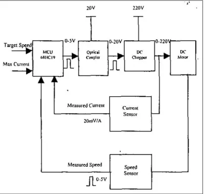
2.1 Block diagram of automatic speed control system 6
3.1 Block diagram of PI speed controller system for DC motor 13
3.2 Flowchart of project implementation 15
3.3 Gantt chart of project implementation for PSM1 16
3.4 Gantt chart of project implementation for PSM2 17
3.5 Rabbit Core Module 3100 18
3.6 The Rabbit 3000 microprocessor 19
3.7 Rabbit 3000 block diagram 21
3.8 Cascaded output registers for parallel ports 23
3.9 Conceptual module of PWM channel 25
3.10 RCM3000 prototyping board 26
3.11 Graph motor speed Vs armature voltage 29
3.12 DC motor 30
3.13 Internal block diagram of L6205 DMOS Dual Full Bridge
Driver
34
3.14 Schematic diagram for the connection of dc motor driver 35
3.15 DC motor driver 36
3.16 Block diagram of speed feedback circuit 36
3.17 Schematic diagram of speed feedback circuit 37
3.18 Speed feedback circuit 38
3.19 Dynamic C code building process 40
3.20 Parallel port initialization block diagram 42
3.21 Port initialization 44
3.22 Flow to generate PWM signal 46
3.23 PWM signal generated with 20% duty cycle 47
3.24 PWM signal generated with 50% duty cycle 47
3.25 PWM signal generated with maximum duty cycle 48
3.27 Source code of PI algorithm 49
3.28 Flowchart to develop PI algorithm 50
3.29 User defined parameters in the software 52
3.30 Flowchart for the overall structure of speed controller program 53
3.31 State diagram for the overall structure of speed controller
program
54
3.32 Addressing memory component 55
3.33 Actual Memory Mapping For PI Speed Controller Program 56
3.34 Power Supply 57
3.35 Oscilloscope and probe 59
3.36 Block diagram of hardware interfacing 66
LIST OF TABLES
NO TITLE PAGE
2.1 Criteria for Choosing PI tuning method 10
2.2 Effect of the PID parmeters 10
3.1 Truth table of L6205 DMOS Dual Bridge Driver 33
3.2 Components used in building motor driver 35
3.3 Components used in building speed feedback circuit 37
3.4 Specification of oscilloscope 59
3.5 Specification of oscilloscope probe 59
3.6 The pin configuration of RCM3100 63
3.7 The pin configuration of DC motor driver 64
3.8 The pin configuration of speed feedback circuit 65
4.1 Speed behaviours for different Kp and Ki parameters 80
LIST OF ABBREVIATIONS
PI - Proportional-Integral
PID - Proportional-Integral-Derivative
DC - Direct Current
PWM - Pulse Width Modulated
PC - Personal Computer
CPU - Centre Processing Unit
HID - Human Interface Devices
I/O - Input and Output
RAM - Random Access Memory
GUI - Graphical User Interface
ROM - Read Only Memory
MCU -Micro Controlling Unit
RCM - Rabbit Core Module
PLC - Programmable Logic Controller
LIST OF APPENDICES
NO TITLE PAGE
A Source code of speed controller for step reference 92
B Source code of speed controller for ramp reference 93
C Overall memory mapping of program 94
D Datasheet of Rabbit Core Module 3100 95
E Datasheet of L6205 DMOS Dual Full Bridge Driver 96
CHAPTER 1
INTRODUCTION
1.1 Background of Project
The use of PI (Proportional-Integral) controller technique has
become common in industrial application despite continual advances
in control theory. It is widely used as control loop feedback
mechanism for various closed loop systems. The PI controller
attempts to eliminate the error between the measured process variable
and the desired value set point by computing and providing corrective
action to adjust the input signal accordingly. Thus the system can gain
stability and independent to external disturbances. In this project, the
PI controller is used to control a DC motor which is part of actuation
system.
The reasons of the popularity of PI controller in industries are
due to the simplicity of its structure and can be used to control most
of the control processes in industrial plant. The conventional PI
controllers mainly constructed based on the mechanical or electronic
analog devices. However both types of these controllers are no longer
suitable in industrial world. The mechanical type PI controller
(pneumatic controller) often requires costly maintenance because
analog based controller that constructed using analog components
faces constraints of accurate control, environmental disturbances and
difficulties in manual tuning.
Hence this project focuses on the development of a digital PI
speed controller for a DC motor drive using 8 bit Rabbit
Microprocessor. Digital controller implementation has the advantages
as they are relatively cheap, highly reliable and reasonably flexible
with respect to the implementation of the PI speed controller
algorithm. The developed controller system will enable the control of
motor speed via software implementation on the Rabbit
microprocessor.
1.2 Objectives
The title of this project is ‗Development of a PI Speed Controller for DC Motor Drive Using Rabbit Microprocessor‘. The
aim of this project is to develop an embedded PI speed controller
system with Rabbit Core Module 3100 microprocessor as the main
controller of the closed-loop system.
The main objectives are:
To develop a digital Proportional-Integral (PI) speed
controller system using Rabbit Microprocessor.
To develop a closed-loop variable speed control for DC motor
drive that consists of Rabbit microprocessor, DC motor, motor
driver, and other supporting components.
To develop an embedded speed control prototype that is
1.3 Scopes
The project execution can be categorized into scopes of:
Develop a closed-loop system for DC motor by implementing
PI control method through Rabbit Microprocessor.
Design and construct a DC motor power drive for variable
speed application.
Develop PI speed controller algorithm on Rabbit
Microprocessor.
Interface and implement DC motor drive with PI speed
control algorithm and test the functionality of the prototype
CHAPTER 2
THEORY AND LITERATURE REVIEW
2.1 Embedded Microcontroller
Embedded microcontroller is a devise that perform embedded
control. The main differentiating feature of an embedded controller is
that all system operation is not controlled by external PC. In fact the
CPU running the system is actually built into the I/O system itself.
While a typical, slaved data acquisition system is hosted by some type
of general purpose Personal Computer complete with mouse, monitor
and other human interface devices (HID), an Embedded Controller's
processor is usually dedicated to controlling the I/O system and often
does not provide any direct human interface.
Differences between an embedded controller and a standard
PC are easily observed. However, the differences in software are
equally noticeable. While most PCs operating systems for your
desktop and laptop computer are large (in terms of RAM and hard
drive space needed), operating systems developed for embedded
systems are likely to be smaller and have been developed without all
of the built-in GUIs as well as much of office equipment peripheral
Embedded controllers are often the heart of an industrial
control system or a process control application. They may also be at
the center of a portable data acquisition system or remote controller
that allows an application to keep running even if its umbilical link to
the outside world is cut. [1] In this project, Rabbit Microprocessor is
used as main embedded controller for the variable speed drive of a
DC motor.
2.2 DC Motor Speed Control
Speed control of dc motor could be achieved using mechanical
or electrical techniques. In the past, speed controls of dc drives are
mostly mechanical requiring large size hardware to implement.
Advances in the area of power electronics have brought a total
revolution in the speed control of dc drives.
DC drives are widely used in applications requiring adjustable
speed; good speed regulation and frequent starting, braking and
reversing. Some important applications are rolling mills, paper mills
mine winders, hoists, machine tools, traction, printing presses, textile
mills, excavators and cranes. Fractional horsepower dc drives are
widely employed – as servo means for positioning and tracking.
Adjustable speed drives may be operated over a wide range by
controlling armature or field excitation. Speed below rated is
controlled by armature voltage control and above rated using field
excitation variation, development of various solid states switching
devices in the form of diodes, transistor and thyristor along with
various analogue or digital chips used in firing or controlling circuits,
have made dc drives more accessible for control in innumerable areas
of applications.
The solid-state power electronic switching devices can be broadly
Those supplied from ac source. Thyristor bridge rectifiers
(converters)
Those employing dc supply namely choppers and inverter.
[3]
The use of power electronics for the control of electric
machines offers not only better performance caused by precise
control and fast response, but also maintenance, and ease of
implementation. In parallel with the advance in power electronic
there have been great advances in microcontroller-based control
systems due to the microcontroller flexibility and versatility. This is
[image:22.595.133.546.316.707.2]because all the control algorithms are implemented in the software. [2]
2.2.1 Digital Speed Controller for DC Motor
The speed control of DC motor is very crucial, especially in
applications where precision and protection are of essence. [4] The use of stand-alone micro controller for the speed control of DC motor
is past gaining ground. Nicolai and Castagect have shown in their
paper how a microcontroller can be used for speed control. The
operation of the system can be summarized as: the drive forms a
rectified voltage. It consists of chopper driven by a PWM signal
generated from a micro controller unit (MCU). The motor voltage
control is achieved by measuring the rectified mains voltage with the
analog to-digital converter present on the micro controller and
adjusting the PWM signal duty cycle accordingly. [4]
Another system that uses a microprocessor is reported in the
work of Khoel and Hadidi a brief description of the system is as
follows: The microprocessor computes the actual speed of the motor
by sensing the terminal voltage and the current, it then compares the
actual speed of the motor with the reference speed and generates a
suitable signal control signal which is fed into the triggering unit.
This unit drives a H-bridge Power MOSFET amplifier, which in turn
supplies a PWM voltage to the DC motor. [5]
2.3 Proportional-Integral (PI) Controller
A proportional-integral controller (PI controller) is a generic
control loop feedback mechanism widely used in industrial control
essentially only has to determine the best settings for the Proportional,
Integral, and Derivative action terms needed to achieve a desired
closed-loop performance. [6]
2.3.1 Propotional-Integral Control
The proportional term makes a change to the output that is
proportional to the current error value. The proportional response can
be adjusted by multiplying the error by a constant Kp, called the
proportional gain.
Where
* Pout: Proportional output
* Kp: Proportional Gain, a tuning parameter
* e: Error = SP − PV
* t: Time or instantaneous time
Higher Kp value increases the response time and reduces
steady-state error of a system. The contribution from the integral term
is proportional to both the magnitude of the error and the duration of
the error. Summing the instantaneous error over time (integrating the
error) gives the accumulated offset that should have been corrected
previously. The accumulated error is then multiplied by the integral
gain and added to the controller output. The magnitude of the
contribution of the integral term to the overall control action is