City, University of London Institutional Repository
Citation: Badalamenti, C. (2010). On the Application of Rotating Cylinders to Micro Air
Vehicles. (Unpublished Doctoral thesis, City University London)This is the accepted version of the paper.
This version of the publication may differ from the final published
version.
Permanent repository link: http://openaccess.city.ac.uk/8693/
Link to published version:
Copyright and reuse: City Research Online aims to make research
outputs of City, University of London available to a wider audience.
Copyright and Moral Rights remain with the author(s) and/or copyright
holders. URLs from City Research Online may be freely distributed and
linked to.
City Research Online: http://openaccess.city.ac.uk/ [email protected]
On the Application of Rotating Cylinders to
Micro Air Vehicles
By
Carmine Badalamenti
Thesis submitted as part of the requirements for the degree of
Doctor of Philosophy
School of Engineering and Mathematical Sciences,
City University London,
Northampton Square, London, EC1V 0HB
Contents
List of Tables vii
List of Figures viii
Acknowledgements xvi
Declaration xvii
Abstract xviii
Nomenclature xix
1 Introduction 1
1.1 The Rotating Cylinder for MAV Applications . . . 2
1.2 Project Overview . . . 6
1.3 Dissertation Overview . . . 7
2 Micro Air Vehicles: A Review 8 2.1 A Note on Terminology . . . 8
2.2 Unmanned Aerial Vehicles . . . 9
2.3 The DARPA MAV Initiative . . . 14
2.4 The Role of MAVs . . . 18
2.5 Design Philosophy . . . 21
2.6 Current and Future Developments . . . 23
2.6.1 Operational Role and Design . . . 23
2.6.2 Fixed-Wing MAVs . . . 25
2.6.4 Flapping-Wing MAVs . . . 30
2.6.5 Power and Propulsion . . . 33
2.6.6 Structures . . . 36
2.6.7 Control and Navigation . . . 36
2.6.8 Payload Capability . . . 38
3 The Flow Past a Rotating Circular Cylinder 40 3.1 Definitions and Notation . . . 40
3.2 Historical Overview . . . 45
3.3 The Lift and Drag of a Rotating Cylinder . . . 53
3.3.1 Analytical Results . . . 54
3.3.2 Experimental Results 1: Overview . . . 55
3.3.3 Experimental Results 2: Effect of Reynolds number . . . 57
3.3.4 Experimental Results 3: Effect of Aspect Ratio . . . 63
3.3.5 Experimental Results 4: Effect of Endplates and End-shape . . . 64
3.3.6 Experimental Results 5: Effect of Surface Roughness . . . 68
3.3.7 Numerical Results . . . 72
3.4 Boundary Layer Measurements . . . 75
3.4.1 Velocity Profiles and Boundary Layer Thickness . . . 76
3.4.2 Location of the Separation Points . . . 79
3.4.3 Shear Stress Distribution . . . 81
3.5 Surface Pressure Distribution . . . 82
3.5.1 Analytical Results . . . 82
3.5.2 Experimental Results . . . 83
3.6 Torque and Power Requirements . . . 90
3.6.1 Analytical Results . . . 92
3.6.2 Experimental Results . . . 93
3.6.3 Numerical Results . . . 95
3.7 The Wake of a Rotating Cylinder . . . 97
3.7.1 Flow Topology, Vortex Shedding, and the Effects of Rotation . . . 98
3.7.2 The Critical Velocity Ratio . . . 103
3.7.3 Strouhal Number Evolution . . . 105
3.7.4 Secondary Vortex Shedding . . . 109
3.7.5 Effect of Shedding on Force Coefficients . . . 111
3.7.6 Vortex Shedding Lock-on . . . 111
3.8 The Effects of Yaw on a Rotating Cylinder . . . 112
3.9 Multiple Cylinders . . . 114
3.9.1 Overview of Interference Between Stationary Cylinders . . . 115
3.9.2 Interference Between Rotating Cylinders . . . 116
3.10 Wind Tunnel Wall Corrections . . . 118
3.10.1 Overview of Conventional Wall Interference . . . 118
3.10.2 Correction Models for General Bluff-Body Flows . . . 120
3.10.3 Blockage Effects and Correction for a Nonrotating Cylinder . . . 122
3.10.4 Blockage Effects and Correction for a Rotating Cylinder . . . 124
4 Preliminary Design Study and Feasibility Analysis 131 4.1 Design Specifications . . . 132
4.2 Configuration . . . 133
4.4 Stability and Control . . . 148
4.4.1 Independence from Angle of Attack . . . 148
4.4.2 Gyroscopic Effects . . . 149
4.4.3 Longitudinal Static Stability . . . 151
4.4.4 Equations of Motion . . . 152
4.5 Practical Feasibility . . . 161
5 Tests on an Isolated Rotating Cylinder 166 5.1 Experimental Arrangements . . . 167
5.1.1 The Wind Tunnels . . . 168
5.1.2 The Cylinder . . . 170
5.1.3 Endplates . . . 171
5.1.4 Support Structure . . . 171
5.1.5 Cylinder Rotation and Speed Control . . . 173
5.1.6 Wake Measurements . . . 175
5.1.7 Flow Visualisation Methods . . . 178
5.2 Testing Procedure . . . 179
5.2.1 Preliminary T2 Testing . . . 179
5.2.2 T3 Testing . . . 180
5.2.3 Main T2 Testing . . . 182
5.3 Analysis of Data . . . 183
5.3.1 Analysis of Force and Moment Measurements . . . 183
5.3.2 Analysis of Power Measurements . . . 185
5.3.3 Analysis of Time-Averaged Wake Pressure Measurements . . . . 186
5.3.5 Uncertainty Estimates . . . 187
5.4 Wind Tunnel Boundary Corrections . . . 188
5.4.1 Conventional Blockage Correction Equations . . . 188
5.4.2 Hackett’s Equation for Wake Blockage . . . 190
5.5 Results and Discussion . . . 192
5.5.1 Validation of T2 Data, Error Estimates, and Blockage Corrections 193 5.5.2 Comparison with Published Data . . . 196
5.5.3 Effects of Reynolds Number . . . 199
5.5.4 Symmetric End Conditions: Effect of Endplate Size . . . 202
5.5.5 Asymmetric End Conditions: Effect of Endplate Arrangement . . 209
5.5.6 Results with Stationary Endplates . . . 213
5.5.7 Power Requirements . . . 214
5.5.8 Wake Pressure Measurements . . . 217
5.5.9 Vortex Shedding Phenomena . . . 226
5.5.10 Results with a Yawed Rotating Cylinder . . . 233
6 Tests on a Rotating Cylinder Mini-UAV 255 6.1 Experimental Arrangements . . . 255
6.1.1 The Cylinders . . . 257
6.1.2 Cylinder Rotation and Speed Control . . . 258
6.1.3 Fuselage . . . 262
6.1.4 Empennage . . . 264
6.1.5 Propulsion System . . . 266
6.1.6 Support Structure . . . 267
6.3 Analysis of Data . . . 273
6.3.1 Analysis of Force and Moment Measurements . . . 273
6.3.2 Presentation and Correction of Data . . . 275
6.3.3 Analysis of Power Measurements . . . 277
6.3.4 Analysis of Gyroscopic Effects . . . 277
6.3.5 Uncertainty Estimates . . . 277
6.3.6 Wind Tunnel Boundary Corrections . . . 278
6.4 Results and Discussion . . . 279
6.4.1 Cylinder Wall Temperature . . . 279
6.4.2 Force Results . . . 280
6.4.3 Moment Results . . . 291
6.4.4 Effects of Differential Rotation of the Cylinders . . . 302
6.4.5 Propeller Effects . . . 304
6.4.6 Gyroscopic Effects . . . 307
6.4.7 Power Requirements . . . 308
7 Implications for MAV Design and Performance 310 7.1 Vehicle Design . . . 310
7.2 Operational Velocity Ratio Range . . . 313
7.3 Revised Performance Estimates . . . 314
7.4 Stability and Control . . . 317
8 Concluding Remarks 323
9 Recommendations for Future Work 326
List of Tables
3.1 Blockage ratios of experimental studies. . . 128
4.1 Desired MAV specifications. . . 132
4.2 Evaluation matrix for selection of general MAV configuration. . . 135
4.3 Performance model constraints. . . 140
4.4 Approximate cruise performance for three possible rotating-cylinder-based small-UAV configurations. . . 144
4.5 Estimated power requirements of equivalent fixed-wing and rotary-wing small-UAV designs. . . 147
4.6 Breakdown of weights for prototype of basic 250 g rotating cylinder mini-UAV design having two cylinders of sized= 0.04m andb= 0.2m. . . 164
5.1 Investigatable velocity ratio range for various wind tunnel speeds. . . 181
5.2 Estimates of average uncertainty in T2 and T3 force and moment data. . . 188
6.1 Model specifications. . . 256
6.2 Model component weights and balance. . . 257
6.3 Model configuration weights and balance. . . 270
List of Figures
1.1 Small-UAV weight budget comparison. . . 2
1.2 The Flettner rotorships. . . 3
2.1 Operational UAV systems.. . . 11
2.2 Developmental UAV programmes. . . 13
2.3 DARPA initiative MAV designs. . . 15
2.4 The MAV and OAV programmes. . . 17
2.5 Recent developments in ultra small ‘flying sensors’. . . 24
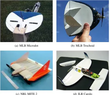
2.6 Fixed-wing MAVs. . . 26
2.7 Non-ducted-fan rotorcraft MAV designs.. . . 29
2.8 Flapping-wing MAV and mini-UAV designs.. . . 32
2.9 The energy density of common power sources. . . 34
2.10 Second generation AeroVironment mini-UAVs. . . 35
3.1 The rotating circular cylinder: axes, dimensions, and notation. . . 41
3.2 Forces and moments on a rotating cylinder. . . 43
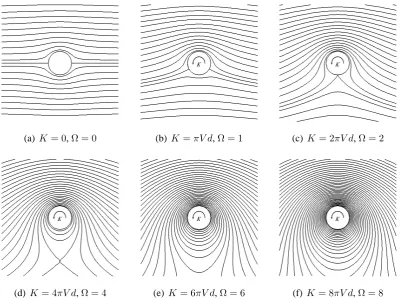
3.3 Potential flow streamlines.. . . 46
3.4 Soviet rotating wing programmes from 1938–1941. . . 49
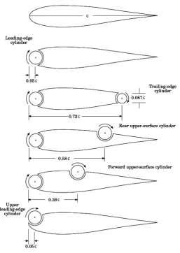
3.5 Overview of typical rotating cylinder configurations for MSBLC application. . . 50
3.6 The NASA rotating cylinder flap programme. . . 51
3.7 Swanson’s results for the lift and drag of a rotating cylinder. . . 56
3.8 Swanson’s results for the effect of high Reynolds number on the lift and drag of a rotating cylinder. . . 58
3.9 Thom’s results for the effect of low Reynolds number on the lift and drag of a rotating cylinder of aspect ratioAR= 8.1.. . . 62
3.11 Effect of endplates on the lift and drag of a rotating cylinder. . . 65
3.12 Thom’s results for the effect of multiple endplates of sizede/d = 3on the lift and drag of a rotating cylinder. . . 66
3.13 Thom’s results for the effect of endshape on lift and drag atRe= 2.19×10⁴. . 67
3.14 Thom’s force results with a sanded cylinder of aspect ratioAR= 8.1. . . 68
3.15 Cross-section and specification of Takayama & Aoki’s cylinder with grooves. . . 69
3.16 Drag of a grooved cylinder. . . 70
3.17 Lift of a grooved cylinder. . . 71
3.18 Numerically derived force data for a rotating cylinder. . . 73
3.19 Swanson’s velocity profiles around a rotating cylinder atRe= 4×10⁴. . . 76
3.20 Swanson’s concept of the origin of the boundary layer on a rotating cylinder. . . 77
3.21 Peller’s velocity profiles around a rotating cylinder atRe= 4.8×10⁴. . . 78
3.22 Peller’s results for the distribution of boundary layer thickness atRe= 4.8×10⁴. 79 3.23 The variation of the separation point angular location with velocity ratio. . . 80
3.24 Experimental shear stress distribution for a rotating cylinder atRe= 4.42×10⁴. 82 3.25 Potential flow surface pressure distribution for a rotating cylinder. . . 83
3.26 Experimental arrangements for measuring the pressure around a rotating cylinder. 84 3.27 Mean pressure distribution around the center section of a rotating circular cylin-der of aspect ratioAR= 7.71, as measured by Thom. . . 85
3.28 Thom’s spanwise distribution of lift and drag forRe= 1.56×10³,AR= 7.71, andΩ = 2. . . 86
3.29 Polar representation of mean pressure distribution about a rotating cylinder. . . . 87
3.30 Comparison of analytical, experimental, and numerical pressure distribution data atΩ = 2. . . 88
3.31 Comparison of lift and drag data derived from pressure distribution integration with that from direct balance measurements. . . 88
3.33 The Chew et al. numerically predicted surface pressure distributions for two-dimensional flow atRe= 1×10³. . . 90
3.34 Torque and power requirements for a rotating cylinder. . . 91
3.35 Invariance of rotating cylinder flap power requirements with velocity, as mea-sured by Weiberg & Gamse. . . 95
3.36 Chew et al.’s numerical power coefficient results forRe= 1×10³. . . 96
3.37 Mittal & Kumar’s results for the total power requirements to both translate and rotate a cylinder atRe= 200. . . 97
3.38 Prandtl’s water surface flow visualisations atRe= 4×10³. . . 99
3.39 Position of the turbulent/non-turbulent interface in the wake of a rotating cylinder.102
3.40 Reynolds dependent transition between steady and periodic flows for a rotating cylinder. . . 104
3.41 Comparison between numerical and experimental results of the Strouhal number variation with velocity ratio. . . 106
3.42 Comparison between the Mittal & Kumar and Stojkovi´c et al. results on the nature of the second shedding mode.. . . 109
3.43 Effect of eccentricity on the Strouhal number. . . 112
3.44 Configuration of cylinders in wind tunnel for Howerton’s tests. . . 113
3.45 Howerton’s results for the forces on a yawed rotating cylinder atΨ = 30◦. . . . 114 3.46 Classification of multiple cylinder configurations. . . 115
3.47 Simplified diagram of Zdravkovich’s interference flow regions between two sta-tionary cylinders for1×103≤Re≤1×10⁵. . . 116
3.48 Howerton’s results for the effects of differential rotation on lift and drag of two coaxial cylinders at2.4×104 ≤Re≤5×10⁴. . . 118
3.49 Comparison of separated-flow corrections for three-dimensional normal flat plates.121
3.50 Comparison of force coefficients at different blockage ratios. . . 129
4.1 Generic MAV mission scenario for design competitions. . . 132
4.3 Conceptual designs for a rotating cylinder MAV. . . 134
4.4 Diagrammatic view of 1930s ‘spindle rotor’ aircraft. . . 137
4.5 Operational space of different rotor geometries. . . 142
4.6 Effect of endplates on the estimated performance of a vehicle with twoAR= 5 rotors (of individual diameterd= 0.04m and spanb= 0.2m).. . . 145
4.7 Reference axes and notation for presentation of equations of motion. . . 153
4.8 Unoptimised prototype rotor system and partial fuselage for basic rotating cylin-der mini-UAV design. . . 163
5.1 The use of louvre doors in the T2 wind tunnel. . . 169
5.2 The cylinder model and endplates. . . 170
5.3 Cylinder support structure for T2. . . 172
5.4 Cylinder support structure for T3. . . 172
5.5 Circuit diagram for motor speed control and power measurement.. . . 174
5.6 Measurement of the cylinder rotational rate. . . 175
5.7 Wake rake dimensions. . . 176
5.8 The wake rake and dynamic pressure transducers. . . 177
5.9 Wake rake and pressure transducer positioning. . . 178
5.10 Wind-on and wind-off strut contribution to forces and moments in T2 and T3.. . 184
5.11 Comparison of wake total pressure variation with velocity ratio for T2 and T3. . 193
5.12 Comparison of lift and drag data for T2 and T3 tunnel tests. . . 194
5.13 Uncertainty estimates for T2 and T3 lift and drag coefficients. . . 194
5.14 Comparison of blockage correction methods.. . . 196
5.15 Comparison of results for cylinder with no endplates to existing data. . . 197
5.16 Comparison of results for cylinder with endplates to existing data. . . 198
5.18 The effects of low Reynolds number on lift and drag for the cylinder without
endplates.. . . 201
5.19 Effects of endplate size on lift and drag. . . 203
5.20 Relative effects of endplate size on lift and drag. . . 204
5.21 The effects of endplates on lift-dependent drag. . . 205
5.22 Effect of endplate size on lift-to-drag ratio.. . . 207
5.23 Effect of endplate size on lateral forces and moments on a rotating cylinder at Ψ = 0◦. . . 208
5.24 Effects of various asymmetric end arrangements on lift and drag. . . 209
5.25 Effect of one free end on the lateral forces and moments on a rotating cylinder at Ψ = 0◦. . . 211
5.26 Effect of mismatched endplates on the lateral forces and moments on a rotating cylinder atΨ = 0◦. . . 212
5.27 Effects of stationary endplates, of sizede/d= 2, on lift and drag. . . 213
5.28 Effect of stationary endplates, of sizede/d= 2, on lift-to-drag ratio. . . 214
5.29 Power requirements for a rotating cylinder.. . . 216
5.30 Spanwise variation of total pressure in the wake at x/d = 5, de/d = 1, and Re= 7×10⁴. . . 218
5.31 Spanwise variation of total pressure in the wake at x/d = 5, de/d = 2, and Re= 7×10⁴. . . 219
5.32 Spanwise variation of total pressure in the wake at x/d = 5, de/d = 3, and Re= 7×10⁴. . . 220
5.33 Spanwise variation of total pressure in the wake atx/d= 5,de/d= 2(with one free end), andRe= 7×10⁴. . . 222
5.34 Spanwise variation of total pressure in the wake atx/d= 5,de/d= 2(stationary plates with a 0.5 mm gap between cylinder and endplate), andRe= 7×10⁴. . . 223
5.35 Spanwise variation of total pressure in the wake at x/d = 3, de/d = 1, and Re= 7×10⁴. . . 224
5.37 Strouhal number variation with velocity ratio forx/d= 3,y/d=−0.6,de/d=
2, andRe= 4.1×10⁴. . . 227
5.38 Power spectra fory/d=−0.6,x/d= 3,Re= 4.1×10⁴, and endplates of size de/d= 2.. . . 228
5.39 Variation of the aerodynamic forces and moments with velocity ratio for a rotat-ing cylinder havrotat-ing no endplates (de/d= 1) at non-zero yaw.. . . 234
5.40 The effects of yaw on the aerodynamic forces and moments on a rotating cylinder with no endplates (de/d= 1). . . 235
5.41 The variation of lift with velocity ratio for a rotating cylinder at non-zero yaw. . 237
5.42 The effects of yaw on the lift of a rotating cylinder. . . 238
5.43 The variation of drag with velocity ratio for a rotating cylinder at non-zero yaw. . 239
5.44 The effects of yaw on the drag of a rotating cylinder. . . 240
5.45 The variation of yawing moment with velocity ratio for a rotating cylinder at non-zero yaw.. . . 244
5.46 The effects of yaw on the yawing moment on a rotating cylinder. . . 245
5.47 The variation of rolling moment with velocity ratio for a rotating cylinder at non-zero yaw.. . . 246
5.48 The effects of yaw on the rolling moment on a rotating cylinder. . . 247
5.49 The variation of sideforce with velocity ratio for a rotating cylinder at non-zero yaw. . . 249
5.50 The effects of yaw on the sideforce on a rotating cylinder. . . 250
5.51 Endplate influence on the sideforce on a rotating cylinder at non-zero yaw. . . . 251
6.1 Overview of the rotating cylinder MAV test model. . . 255
6.2 Cylinder and endplug dimensions. . . 258
6.3 The mechanism for rotation of the cylinders. . . 260
6.4 Circuit diagram for motor speed control and power measurement.. . . 262
6.5 The fuselage. . . 264
6.7 The propulsion system. . . 267
6.8 Views of the model mounted in T2. . . 268
6.9 Model configurations used during wind tunnel testing. . . 269
6.10 Definition of reference areas and lengths for analysis of vehicle model test data. . 274
6.11 Axes for correction and presentation of vehicle model results. . . 276
6.12 Changes in cylinder surface temperature during a typical test run. . . 280
6.13 Lift coefficient results for the vehicle model without tail atRe= 1.83×10⁴. . . 281
6.14 Lift coefficient results for the vehicle model with tail atRe= 1.83×10⁴. . . . 283
6.15 Drag coefficient results for the vehicle model without tail atRe= 1.83×10⁴. . 284
6.16 Drag coefficient results for the vehicle model with tail atRe= 1.83×10⁴. . . . 285
6.17 Lift-to-drag ratio results for the vehicle model atRe= 1.83×10⁴. . . 287
6.18 Variation of sideforce coefficient with velocity ratio for the vehicle model with and without vertical fin atRe= 1.83×10⁴. . . 288
6.19 Variation of sideforce coefficient with angle of attack for the vehicle model with and without vertical fin atRe= 1.83×10⁴. . . 289
6.20 Variation of sideforce coefficient with yaw angle for the vehicle model with and without vertical fin atRe= 1.83×10⁴. . . 290
6.21 Pitching moment coefficient results for the model without tail atRe= 1.83×104.291
6.22 Pitching moment coefficient results for the model with tail atRe= 1.83×10⁴. . 293
6.23 Variation of yawing moment coefficient with velocity ratio for the vehicle model with and without vertical fin atRe= 1.83×10⁴. . . . 295
6.24 Effect of velocity ratio ondCn/dΨfor the vehicle model with and without ver-tical fin atRe= 1.83×10⁴. . . 296
6.25 Variation of yawing moment coefficient with angle of attack for the vehicle model with and without vertical fin atRe= 1.83×10⁴. . . 296
6.27 Variation of rolling moment coefficient with velocity ratio for the vehicle model with and without vertical fin atRe= 1.83×10⁴. . . 299
6.28 Variation of rolling moment coefficient with angle of attack for the vehicle model with and without vertical fin atRe= 1.83×10⁴. . . 300
6.29 Variation of rolling moment coefficient with yaw angle for the vehicle model with and without vertical fin atRe= 1.83×10⁴. . . 301
6.30 The effects of differential rotation of the cylinders on the aerodynamic forces and moments for configuration 5 atα= 0◦,Ψ = 0◦, andRe= 1.83×10⁴. . . . 303 6.31 Propeller effects on the longitudinal forces and moments atRe= 1.83×10⁴.. . 305
6.32 Propeller effects on the lateral forces and moments atRe= 1.83×10⁴. . . 306
6.33 Comparison of the variation withΩof the gyroscopic and aerodynamic lateral moment coefficients atRe = 1.83×10⁴ and various values of yaw angle, roll rate, and yaw rate. . . 308
6.34 Power requirements for spinning the cylinders atRe= 1.83×10⁴. . . . 309
7.1 Possible configurations of interest for a rotating-cylinder-based small-UAV. . . . 313
7.2 Revised performance estimates for two rotors of sized = 0.04 m,b = 0.2 m,
Acknowledgements
Many thanks to my brother, whose knowledge of Photoshop, and willingness to share it,
was instrumental in getting everything “just right”.
I’d also like to extend my gratitude to Mr Mike Smith, Mr Chris Barber, Mr Tim Barnes,
and Mr Jim Ford for their invaluable technical assistance in realising the experimental
Declaration
I grant powers of the discretion to the University Librarian to allow my thesis to be copied
Abstract
An investigation into the feasibility of using rotating circular cylinders as the primary means of generating lift for the class of very small (0.15 m maximum dimension, 50 g weight) unmanned aircraft known as Micro Air Vehicles (MAV) has been carried out. It is hoped that such a design would be able to exploit the large lift generating properties of the rotating cylinder for the purposes of increasing the available payload weight. This would provide considerable benefits as, at present, the inability to support capable payloads significantly restricts the usefulness of MAV-sized craft.
A preliminary design study was performed to investigate possible configurations for the proposed design, resulting in the selection, for reasons of simplicity, of an arrangement having two rotating cylinders about a central fuselage. Initial assessments of the practical feasibility of such a design, as well as its likely performance (in terms of lift, drag, and power requirements) were then carried out. An examination of the consequences of the presence of the cylinders on the stability and control of such a vehicle was also performed.
Existing understanding of the aerodynamic characteristics of a rotating cylinder in cross-flow was extended through a series of wind tunnel tests examining all aspects of rotating cylinder flow, including force and moment coefficients, behaviour at non-zero yaw angles (−30◦ ≤Ψ≤10◦), power requirements for spinning the cylinder, and wake phenomena. A particular focus was the use of endplates to improve aerodynamic performance. The tests were conducted with a cylinder of aspect ratioAR = 5across a range of Reynolds numbers (1.6×10⁴ ≤ Re ≤ 9.5×10⁴, based on cylinder diameter) and velocity ratios (Ω≤ 4) identified as being of interest by the preliminary design study. The results were generally found to be in very good agreement with existing published data, though power requirements for spinning the cylinder were much higher than anticipated, and revealed the influence of tip vortices to be of great significance.
Wind tunnel experiments with a simple prototype aircraft, based on the outcome of the preliminary design study and isolated cylinder tests, examined the overall aerodynamic performance of this type of design for a single Reynolds number ofRe= 1.8×10⁴, across
a velocity ratio range ofΩ ≤ 2.5, and at various angles of attack (−10◦ ≤ α ≤ 25◦) and yaw (−10◦ ≤ Ψ ≤ 30◦). These tests also investigated the interaction between the cylinders and the other components of the aircraft to help determine the most favourable layout. The tests revealed the effect of propeller wash over the rotors, the influence of the cylinder wake on the tail, and the design of the tail, fin, and fuselage to be of considerable importance to the aerodynamic characteristics and performance of the vehicle.
Nomenclature
English Symbols
a Cylinder radius
A Model frontal area
AR Aspect ratio
b Cylinder span
B Wind tunnel working section width
c Chord length
C Wind tunnel working section cross-sectional area
CD Drag coefficient
CD∞1 Drag coefficient corrected by Maskell’s one-step method
CD0 Profile drag coefficient
CDf Skin friction drag coefficient
CDi Induced drag coefficient
CDs Separated flow drag coefficient
Cf Skin friction coefficient; Shear stress coefficient
Cl Rolling moment coefficient
CL Lift coefficient
Cm Pitching moment coefficient
Cn Yawing moment coefficient
Cp Pressure coefficient
CP Power coefficient
CQ Torque coefficient
CY Sideforce coefficient
d Cylinder diameter
de Endplate diameter
D Drag
e Oswald efficiency factor
f Frequency
fb Body carried frame of reference fixed to the aircraft
fc Body carried frame of reference fixed to the cylinder
fe Inertial frame of reference fixed to the Earth
fs Vortex shedding frequency
F Frictional force on cylinder surface
g Acceleration due to gravity
G Vector of external moments
H Vector of angular momentum
H Wind tunnel working section height; Total pressure
it Tail setting angle
I Current
I Moment or product of inertia of aircraft
J Moment or product of inertia of rotor
k1 Lift-dependent profile drag factor
k2 Induced drag factor
K Circulation; Lift-dependent drag factor
Kv Motor speed constant
l Rolling moment
l1 Distance betweenoixiyiziandowxwywzy
m Pitching moment; Mass
M Mach number; Resultant aerodynamic moment about body fixedyaxis
n Yawing moment
N Rotational rate; Resultant aerodynamic moment about body fixedzaxis
p Static pressure; Rate of roll
P Total power required for flight; Power requirements for spinning an isolated
rotat-ing cylinder
PH Power required for hovering flight
PR Power required to spin both rotating cylinders
PS Power required for onboard systems
PT Power required for horizontal translational flight
q Dynamic pressure; Rate of pitch
Q Torque
r Radial coordinate; Rate of yaw
Re Reynolds number based on cylinder diameter
Reb Reynolds number based on body diameter
Rec Reynolds number based on chord length
Re` Reynolds number based on characteristic length
s Total length of both rotors
S Model reference area; Longitudinal spacing between multiple tandem cylinders
S Center-to-center spacing between multiple staggered cylinders
Sa Actuator disc reference area
Sw Wing reference area
St Strouhal number
t Thickness
u Linear velocity alongxaxis
U Resultant speed through actuator disc
v Linear velocity alongyaxis
V Voltage
V Velocity
Vr Peripheral velocity
w Linear velocity alongz axis
W Weight
x Cartesian coordinate
X Resultant aerodynamic and thrust force alongxaxis
y Cartesian coordinate
Y Sideforce; Resultant aerodynamic and thrust force alongyaxis
z Cartesian coordinate
Z Resultant aerodynamic and thrust force alongzaxis
Greek Symbols
α Geometric angle of attack
αs Stall angle
β Sideslip angle; Angular coordinate around cylinder circumference
γ Angle of climb or descent
Γ Rotor angular velocity
δ Boundary layer thickness
Total correction factor due to solid and wake blockage
s Correction factor due to solid blockage
w Correction factor due to wake blockage
η Electrical efficiency
θ Euler angle about localyaxis; Angular coordinate
Λ Body-shape factor for wind tunnel wall interference
ν Kinematic viscosity of air
ρ Density of air
τ Wind tunnel shape factor for wall interference calculation
φ Euler angle about localxaxis
ψ Euler angle about localz axis
Ψ Yaw angle
ω Angular velocity
ω Vector of angular velocity of complete aircraft
Ω Velocity ratio
Ωc Critical velocity ratio for suppression of vortex shedding
ΩK Velocity ratio for whichCL= 0during Magnus effect inversion
Ω Vector of angular velocity ofoxyztoOxeyeze
Subscripts
∞ Associated with freestream conditions
0 Associated with initial conditions
b Associated with framefb
base Associated with cylinder base conditions
c Corrected quantity
cyl Cylinder
C Control term
e Associated with framefe
i Associated with the intersection of the model longitudinal axis and the cylinders’
axis of rotation
int Associated with interference effects
m Measured quantity
max Maximum
min Minimum
rel Relative to cylinder surface
strut Associated with the model support structure
tot Total
w Associated with the attachment point between the T2 balance and the model
Superscripts
b Relative to or within framefb
1
Introduction
The success of Unmanned Aerial Vehicles (UAV) such as Predator and Global Hawk
has led to a recent surge of interest in all aspects of unmanned flight and an examina-tion of the possible military relevance of very small UAVs known as Micro Air
Vehi-cles (MAV). Generally defined as having a maximum linear dimension no greater than 6”
(0.15 m) and typically weighing a few hundred grams at most, this type of unmanned
plat-form came to prominence during the mid-1990s through a Defence Advanced Research
Projects Agency (DARPA) led investigation into micro-aircraft.
The envisaged role for MAVs is as a provider of local reconnaissance and surveillance
for small military units, or individual soldiers, in both traditional battlefield scenarios
and more exotic conditions, such as jungle or urban environments. MAV-scale vehicles
have only become possible due to recent advances in the miniaturisation of technologies
for propulsion, power, sensors, and actuators, but there are still many obstacles to be
overcome before MAVs enjoy the same level of acceptance from the defence sector as
larger UAVs. Meeting the many stringent technological requirements of MAV-scale flight whilst providing a suitable mission capability has proved particularly difficult.
The majority of existing MAV designs are of a fixed-wing nature, many of which are of the flying-wing type. A number of rotary-wing and flapping-wing designs also exist but
are hampered by limited information on the aerodynamics of flapping and rotary flight at
the low Reynolds numbers at which MAVs operate (typically2×104 ≤Re
` ≤2×10⁵).
This lack of fundamental knowledge is also problematic for current fixed-wing designs,
which tend to suffer from low lift coefficients, high drag, and reduced payload weights
(as a percentage of total vehicle weight).
Analysis of existing small-UAV and MAV designs reveals a trend of rapidly decreasing
payload weight percentage with decreasing size (see Figure 1.1). In fact, empirical data
suggests the available payload weight reduces almost five times more rapidly than the
vehicle weight.1 Given the smaller mass of smaller craft, this places a considerable
con-straint on the size and type of payload that can be realistically carried at these scales. The
lack of available space for the storage of propulsive and systems energy, and the result-ing short flight durations, further compound the problem. Consequently, current MAV
designs are limited to fairly short range, low endurance missions, with restricted sensor
capability, and reduced communications. This has led to the focus moving away from
6”-sized craft for the time being whilst solutions to these problems are sought.
good opportunity to explore unconventional solutions to such problems. Additionally,
with the need to accommodate a human pilot now removed, along with some of the
as-sociated constraints forced on aircraft designers, there is also an incentive to re-evaluate
many previously discarded concepts that are impractical for full-scale manned aircraft,
but which may well be beneficial when viewed in the context of UAVs and MAVs. One such idea that could now have merit when applied to an MAV-type platform is that of
generating lift with a rotating cylinder.Extender
(3m span) Payload 56% Propulsion and Power 13% Structure 18% Other 13%
(a) Extender (3.10)
Dragon Eye (1.13m span) Propulsion and Power 35% Structure 30% Other 9% Payload 26%
(b) Dragon Eye (1.13)
MITE (0.46m span) Propulsion and Power 38% Payload 18% Structure 38% Other 6%
(c) MITE (0.46)
AeroVironment Black Widow (0.15m span, m=60g)
Other 9% Structure 17% Payload 12% Propulsion and Power 62%
(d) Black Widow (0.15)
Figure 1.1: Small-UAV weight budget comparison1. Numbers in brackets denote vehicle wingspan in metres.
At present, the inability to support useful payloads significantly restricts the usefulness of
MAV craft. Successful exploitation of the large lift generating capabilities of the rotating
cylinder (CL > 10is known to be possible) could greatly benefit all mission capability
related areas. In particular, a significant increase in available payload weight could be
achieved. This would enable the use of larger, more sophisticated sensors or the carriage
of multiple sensors that could then be linked together to provide better autonomy, leading
to advanced mission roles or novel applications.
Although continuing miniaturisation of technologies will always provide smaller, more
capable payloads, the inherent extra lifting potential of a rotating cylinder platform would
remain an advantage. This makes the idea worthy of investigation. The high value of the obtainable lift coefficients also raises the possibility of very low speed flight, creating a
platform possessing some of the qualities of both fixed-wing and rotary-wing vehicles.
HighCLvalues have also been associated with a reduction in the overall size of MAVs.2
1.1
The Rotating Cylinder for MAV Applications
Previous attempts at exploiting the large forces available from a spinning cylinder have
is not much more than a novelty. Indeed, the rotating circular cylinder has not been
se-riously considered as a means of primary lift generation for an aircraft since the early
decades of the last century when the introduction of the Kutta-Joukowski theorem led to
much speculation and investigation into the ‘Magnus effect’ and it’s possible pertinence
to aircraft flight.3 More recent efforts at practical application of the concept have mostly concentrated on its use as a high-lift device (trailing or leading edge flap) for STOL type
aircraft,4–6but have not reached fruition. To date, the only moderately successful
applica-tion of the Magnus effect in an aeronautically related field has been the Flettner rotorship.
(a) The Buckau (b) The Barbara
Figure 1.2: The Flettner rotorships.
In 1925, Anton Flettner published a number of papers describing his application of the
principles of rotating cylinders to the propulsion of ships.7 He had originally been
con-sidering the use of aerodynamic metal sails, but realised the potential of rotating cylinders when he learned of recent experiments at the Aerodynamische Versuchsanstalt G¨ottingen
(AVA), in Germany.8–10 Confident that his idea would work, in 1926 he converted the
sailship ‘Buckau’ (later renamed ‘Baden Baden’) by fitting it with two 18.5 m high, 2.8 m
diameter cylindrical rotors orientated with the longitudinal axis vertical and capped with
small endplates (see Figure 1.2a).
In a crosswind, rotation of the cylinders about the longitudinal axis produced a propulsive
force acting perpendicular to the wind direction. This force was many times greater than
that generated by a conventional sail of equivalent size, yet the drag of the new rigging
was substantially lower. The rotors were also quicker and easier to adapt to a change in
wind-speed than a sail, were able to utilise higher wind-speeds without fear of damage,
and also greatly enhanced turning and manoeuvrability. The rotorship design was well received and, on the orders of the German navy, a second ship, ‘Barbara’, became the first
Though in regular commercial service during the late 1920s, the rotorships did not gain
widespread popularity and their dependence on wind conditions proved a crucial failing.
The demand for a steady service and an abundance of cheap fuel meant that the concept
of the Flettner rotor was abandoned in favour of propeller-driven craft. Despite a small
revival during the fuel crisis of the 1970s, the potential of the rotorship was never fully realised.11
That Flettner was able to obtain a level of success that has so far eluded other attempted applications is a consequence of the operational conditions associated with a sailing ship
setting. As Betz8noted, these were especially favourable to the rotating cylinder concept.
For most cases in which lifting forces are required, the flow velocity is so high that, to
obtain a sufficient lift as to be advantageous, the rotational speed of the cylinder becomes
prohibitively large. The high power requirements and associated technical difficulties
would then nullify any benefits that could be gained.
By contrast, the wind velocities at which the Flettner rotorships achieved maximum
ef-ficiency were not very high at all, being on the order of 5 to 10 m/s. Consequently, the
required peripheral velocity was only moderately high (≈ 20to30m/s) and, due to the
large size of the cylinders, the necessary rotational rate remained quite low even at the
highest wind speeds. The large drag associated with a bluff body such as a cylinder was
also not so problematic: the conventional sail that it replaced performed even worse in this regard.
The unfavourable operating conditions associated with full-scale flight are just one reason why rotating cylinders are ill-suited to the task of providing lift for conventional-sized
aircraft. Several other prominent objections may be raised. The lack of moving parts
that a conventional wing provides is both mechanically and structurally more convenient.
Furthermore, since the generation of lift from a rotating cylinder is not a passive process, a
partial power failure on an aircraft with rotating cylinders in place of wings would create a
strong inequality of lift that would present serious control difficulties. A complete power
failure would be immediately disastrous.
The most basic objection to a rotor aircraft is the inefficiency of a rotating cylinder as
a lifting medium. Existing data12 suggests a maximum lift-to-drag ratio of between five
and six, which is substantially less than that of a typical aerofoil. In noting the many
at-tempts between 1850 and 1930 at applying the Magnus effect to generating lift, Klemin13
concluded that this is the fundamental handicap that must be overcome if a rotor airplane design is to succeed. Prandtl9went further, stating that he saw no practical advantage in
a propeller, in windmills, or for similar applications. However, the use of rotating
cylin-ders to generate lift for MAV-scale craft immediately eliminates many of these objections.
As with Flettner’s rotorships, an MAV platform offers similarly favourable operating
con-ditions for rotating cylinder application. With no crew or passengers to endanger and a
low overall cost, vehicle loss due to power failure would be reduced to the level of any
other system malfunction. The small size and flight speeds would dictate that the absolute
values of drag and power remain relatively small and, although larger than for a fixed-wing MAV, the indications are that the power and propulsive requirements are likely to
be within the limits of what is achievable with existing technologies of a suitable size.
In any case, the anticipated improvements in mission capability resulting from a greater
payload capacity would be expected to outweigh the associated costs of larger drag forces
and increased power.
Most importantly, the poor performance of aerofoils when operating at the low Reynolds
numbers of MAV flight means that the lift-to-drag ratios of a rotating cylinder and
con-ventional wing are of similar magnitude in these conditions. Furthermore, the literature
suggests that low drag and a high lift-to-drag ratio may be relatively unimportant for
MAV-scale flight. Instead, multi-disciplinary optimisation (MDO) studies2 indicate that
the best improvements in design can be achieved by increasing the maximum lift.
In this regard, rotating cylinders would be well-suited to MAV application as, based on the
incredibly high lift coefficients reported by CFD investigations (CL>20forRe≤ 200),
rotating cylinder aerodynamics is actually somewhat improved at low Reynolds number. The lift from a rotating cylinder is also largely unaffected by the problems associated
with laminar separation bubbles that plague fixed-wing aircraft at lowRec. With rotating
cylinders, these effects are relegated to a generally unattractive region of the lift curve
that would not, in any case, be suitable for MAV operation. Instead, at the point at which
the maximum lift-to-drag ratio occurs, such effects have already been eliminated by the
transition-inducing effects of rotation.
Despite such favourable aspects, an MAV application is not without its difficulties.
Al-though the low flight speed also leads to correspondingly low peripheral velocities, the
small size implies greater rotational rates will need to be implemented. Incorporating
a rapidly spinning cylinder into an MAV design adds a further level of complexity to
an already difficult problem and may bring technological difficulties that would increase
overall structural weight and reduce the potential benefits to payload capability. To fully make use of this potential, and justify the increased complexity, requires a vehicle whose
rotating cylinder concept to be reserved for payload weight. However, successful
realisa-tion of such a design is made more difficult by a significant lack of experimental data on
all aspects of rotating cylinder flow.
1.2
Project Overview
The purpose of the present work is not primarily to build or design a demonstrator vehicle
for a UAV platform, at or near the MAV size limit, that is centered around the use of
rotating circular cylinders as the primary means of generating lift, but rather to determine
the feasibility of such a vehicle and to improve the scientific and technical knowledge required for its development. Towards this end the following steps were carried out:
• Analysis of the existing literature with a view to identification, examination, and discussion of the shortcomings, inconsistencies, or gaps in the data that might
im-pact on the project by preventing the feasibility assessment or by hindering the
design and development of the platform.
• Commencement of a preliminary design study and performance analysis using the data collected from the literature to assess overall feasibility, estimate performance
quantities for a range of possible vehicle masses and cylinder sizes, and provide a
consideration of the stability and control of such a class of flight vehicle.
• Planning and execution of an experimental testing programme on an isolated ro-tating circular cylinder with emphasis on verifying the aerodynamic behaviour and
filling any gaps in the literature. Specifically, this pertained to the collection of data
regarding three-dimensional characteristics, power requirements, and lateral force
and moment data.
• Examination of the aerodynamic characteristics of the vehicle as a whole through wind tunnel testing of a near-full-scale model of the proposed design.
• Reassessment and refinement of the design based on the outcome of the isolated cylinder and vehicle model tests with a view to the establishing of a preferred
con-figuration and the future development of a prototype for free-flight tests.
By providing details of, and results from, the above outlined investigations, the present work thus aims to be of use to any future research efforts into rotating-cylinder-based
1.3
Dissertation Overview
The outline for the rest of this document is as follows: Chapter 2 reviews the current
state-of-the-art of MAVs. Beginning with a brief summary of general UAV activity, the chapter
highlights the designs, technologies, and lessons learnt from the first decade of MAV
research and discusses expected future developments. Due to the considerable growth
of research activity in this field, the review in Chapter 2 is representative rather than
exhaustive.
Chapter 3 provides a comprehensive overview of rotating cylinder flow and its typical
fea-tures. Details on all aspects of the flow, from force behaviour through to wake phenomena
and power requirements are included. The focus is on the comparison and analysis of the
existing research so as to provide an understanding of how best to employ the cylinders and identify areas requiring further research.
Chapter 4 is the preliminary design study examining the feasibility of an MAV design based on rotating cylinders as the primary means of lift generation. The assessment
con-siders possible designs in light of the aerodynamic behaviour and available technologies,
presents performance estimates based on existing data and discusses the implications of
the design on the stability and control of such a craft.
Chapters 5, 6, and 7 are concerned with the experimental tests on the isolated cylinder and
vehicle model. They describe the experimental equipment, arrangements, and procedures
used to carry out the experiments and analyse the results. The outcome of the tests, and
the implications of the findings, are also thoroughly discussed. A particular focus of the
discussion in Chapters 6 and 7 is the impact of the data on vehicle design.
Finally, Chapters 8 and 9 summarise the conclusions of the present study and give
2
Micro Air Vehicles: A Review
Despite the relatively short history of research into micro-aircraft, recent exponential
growth in this field has led to the development of a large number of vehicles designed to operate in many different roles. This chapter provides background information on the
history, role, design, and possible future development of MAV-scale aircraft. Although
the focus is on MAVs, other classes of small-UAVs are, by necessity, discussed too. In
addition, a brief summary of general UAV activity is also included so as to provide a
context for the current proliferation of unmanned aircraft, of whatever size. The chapter
begins with a clarification of the numerous terms and definitions that have emerged to
describe all such aircraft.
2.1
A Note on Terminology
“UAV: A powered aerial vehicle that does not carry a human operator, uses
aerodynamic forces to provide vehicle lift, can fly autonomously or be
pi-loted remotely, can be expendable or recoverable, and can carry a lethal or
non-lethal payload. Ballistic or semi-ballistic vehicles, cruise missiles, and
artillery projectiles are not considered unmanned aerial vehicles.”
At present there exists no single internationally recognised definition of a UAV. The above
quote is taken from the US Department of Defence’s (DoD) dictionary of military terms14
and was chosen as representative of the vehicle class discussed throughout this
docu-ment. Further, the DoD has been at the forefront of this technology and many of their
terms and standards have become the defacto terms and standards for the entire field.
The UK definition of a UAV, as provided by the CAA’s airworthiness requirements for unmanned flight,15 is far simpler than its American counterpart (an aircraft which is
de-signed to operate with no human pilot on board), but effectively the same. Alongside
such all-encompassing definitions are many different unofficial classification systems for
unmanned craft, of which the most commonly accepted are by mission group (Tactical,
Strategic, Combat etc.) or design environment (HALE, MALE etc.), though some nations
favour classification by mass or speed.
Micro air vehicles occupy the extreme end of the UAV spectrum and are the only type
to be classified solely by size. Though generally defined as having a maximum
char-acteristic dimension (span or length etc.) of 6” or less, there are actually many different
to include vehicles with a maximum dimension of less than 0.5 m.16
Between the limits of UAV and MAV are a wide range of different sized vehicles that
go by various names such as gun-launched UAV, man-portable UAV, back-packable UAV,
parasite UAV, maritime UAV, micro UAV, mini aerial vehicle, and so forth. Until recently,
all such craft were classified by the DoD under the slightly nebulous term of ‘small-UAV’
(S-UAV), but this has now seemingly fallen out of use. In their most recent documents,17
the term ‘mini-UAV’ has been adopted instead. Although generally being applied to vehi-cles with a wing span of less than 10 ft, no formal definition for this term appears to exist,
reflecting the fact that no official classification criteria for UAV either by size or weight
has been adopted by the DoD or any other organisation.
The situation has recently been further complicated by a switch in DoD terminology17
away from UAV in favour of Unmanned Aircraft System (UAS), within which the flying
component of the system is referred to as an Unmanned Aircraft (UA). This change in
terminology was designed to reflect the fact that the aircraft is only one component of a
system that is made up of multiple parts, including ground stations, personnel, and other
elements, and is in line with the Federal Aviation Authority (FAA) decision to treat UAVs
as aircraft for regulatory purposes.
Where unmanned aircraft are discussed in this document it is generally in reference to the
actual vehicle itself, rather than the system as a whole; thus, the term UAV, as opposed
to UAS, will be retained. Where a specific craft is discussed, UAVs of any type will be
referred to by the manufacturers designation, if any, or by the operational designation if it is in service. If necessary, a short comment on size, weight, or mission class will also be
made. For general descriptive purposes, the term mini-UAV will be applied to describe
any UAV with characteristic dimension greater than 6” but less than or equal to 10 ft.
The term MAV will be reserved for those crafts with a characteristic dimension of less
than or equal to 6”. Where both vehicle types are referred to simultaneously they will be
described as small-UAVs.
2.2
Unmanned Aerial Vehicles
Whilst it is only recently that the field of UAVs has publicly come to the fore, there has
in fact been a long tradition of military usage of unmanned systems throughout much
of aviation history, though many of these craft were not UAVs as specifically defined
above. Hot air balloons filled with explosives were used at least as far back as 1849,
recon-naissance, for anti-aircraft gunnery training, or as crude cruise missiles since the early
decades of the twentieth-century. The use of unmanned craft of a more sophisticated
na-ture began during the Vietnam War when technology had progressed to a sufficient level
as to enable UAVs (such as the Teledyne Ryan AQM-34 Firebee photo-reconnaissance
drone) to be more effective. Since then, UAVs of one type or another have played a role in the majority of recent conflicts, including the Balkans, both Persian Gulf campaigns,
and Afghanistan, where their role is still ongoing. Much of this involvement has been in
a limited or secondary role, but the success of UAV deployment in Kosovo, Afghanistan,
and Iraq has led to a significant increase in worldwide UAV spending that, along with
increasing payload capabilities, growing intolerance to loss of life, and increased press
and public awareness, is likely to further add to the proliferation of this technology.
Though most UAV research and production now occurs in the US, the majority of smaller
tactical UAV systems are fielded and tested in Israel and Europe, both early adopters
of unmanned technology.18 Israel was the first country to employ what would now be
regarded as a UAV. Begun in 1974 as a response to the regional political situation of the
late 1960s and early 1970s, Israel’s UAV programme has made it the most experienced user and a worldwide leader reportedly having some forty-five live UAV programmes (as
of 2009).19 Unmanned vehicles were also quickly taken-up in Europe, where Belgium
has operated the EPERVIER (Sparrowhawk) system since 1977. At least sixteen EU
member states now have an active UAV programme and several have been pursuing an
Unmanned Combat Aerial Vehicle (UCAV) system through multinational programmes
such as ‘nEUROn’ and ’Barracuda’.16, 20 Although the UK is not a participant in either
programme it remains at the forefront, alongside France and Germany, of European UAV
activity.
Unmanned aerial vehicles are currently a high priority as the UK has cancelled plans for
its next-generation manned combat aircraft. Furthermore, the technology-transfer
prob-lems encountered with the Joint Strike Fighter, has led to the UK pursuing an
indepen-dent UAV capability.21 Current UK UAV efforts are managed by the Ministry of De-fence’s (MoD) Unmanned Air Systems team, which was formed from the merger of the
UK Government’s Strategic Unmanned Air Vehicles (Experiment) programme (SUAVE)
and the Tactical Unmanned Air Vehicles (TUAV) Project team, and is responsible for
di-recting UK acquisition policy on unmanned aircraft and guiding future research. Systems
presently under development include the Desert Hawk III mini-UAV; a UCAV technology
demonstrator programme, codenamed ‘Taranis’; and the Watchkeeper TUAV, intended as
a replacement for the ageing Phoenix and expected to enter service in 2010.
was initially erratic. Despite flirting with UAV technology during World War II (under
the aborted Operation Aphrodite) and having several programmes during the 1960s, by
the end of the Vietnam War all the various American UAV projects were cancelled due
to defence budget cuts. US interest was later rekindled by Israel’s use of UAVs during
the 1982 invasion of Lebanon. Israeli experiences with the Scout and Mastiff mini-UAVs convinced leaders in the US Navy of the need to acquire the Scout and, furthermore, to
pursue the development of their own reconnaissance drones. This decision would lead
to the 1986 procurement of the Pioneer full-scale UAV. Following particularly successful
deployments of Pioneers during the first Gulf War, American military officials further
recognized the worth of unmanned systems and the 1990s saw the introduction of the
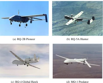
Hunter, Predator, Shadow, and Global Hawk systems (see Figure 2.1). The success of
these systems has led directly to the growth in demand for UAV technology currently
being experienced.
(a) RQ-2B Pioneer (b) RQ-5A Hunter
[image:37.595.123.476.317.601.2](c) RQ-4 Global Hawk (d) MQ-1 Predator
Figure 2.1: Operational UAV systems.
To date, unmanned aircraft have primarily been tasked with the provision of
reconnais-sance, but the increasing sophistication of modern UAVs is leading to more varied scope
in the types of missions being performed. These now include roles as expendable
UAVs are generally preferred for those tasks for which manned missions are ill-suited or
present unacceptable risks.
When applied to such missions, commonly known as ‘the dull, the dirty, and the
danger-ous’,17, 22 UAVs offer several advantages over manned aircraft. UAVs are able to free up
personnel from man-intensive extended sentry and reconnaissance missions, whilst
offer-ing better sustained alertness (the dull); they can perform aerial surveyance and physical
sampling of radiologically, chemically, or biologically contaminated areas without risk to human life (the dirty); or can undertake high-risk Suppression of Enemy Air Defences
(SEAD) missions with less need for supporting aircraft, a lower political and human cost
of mission failure, and a higher probability of success (the dangerous). The advantages
offered by unmanned systems within these areas has led some to suggest that UAVs may
at some point almost fully supplant manned aircraft in a large number of roles.
Though there have been other similar claims made throughout the last century of manned
flight that subsequently turned out to be false (the 1957 UK Defence White Paper
set-ting forth the future of the RAF is a particularly good example), the growing spread of
unmanned technology and the seriousness with which the defence sector is taking UAVs
cannot be ignored. In their 2005 roadmap17for the long-term strategy of US UAV
devel-opment and acquisition, the DoD noted that UAVs have matured to the point where it is
no longer necessary to look for niche missions. Instead of asking “Can we find a mission for this UAV?”, the question now is “Why are we still doing this mission with a human?”.
The growing trend towards the use of unmanned systems will undoubtedly transform the way many military and military support operations are conducted. However, the
prolifer-ation of this technology should not be seen as a indicprolifer-ation of manned aircraft inadequacy
but rather as another facet of the continuing drive to replace man-power with
technol-ogy.23 This is of particular importance in the current era where many armed forces are in
the process of restructuring or reducing their military power yet also seeking to maintain
the ability to purposefully intervene wherever their interests are threatened.
The possible future development and deployment of UAVs in military roles was outlined
in the 2002 DoD roadmap,22which covered the expected evolution in design and usage of
UAVs during the twenty-five year period from 2002 to 2027. This anticipated the
intro-duction of F-16 sized UAVs in a number of combat and combat support roles occurring
as early as 2012. Such missions would be made possible by improvements in power,
communications, and sensor capabilities, which would allow these craft to operate with a significant degree of autonomy and be able to engage in real-time multi-vehicle
UAVs with very high endurance capabilities would begin to emerge by 2012 was also
expressed. By the end of the development period, morphing airframe UAV systems that
are able to change their shape to serve the current mission and environmental conditions
were envisaged. The use of shape memory alloys and stretching skins would allow such
crafts to perform aerodynamic manoeuvres impossible for manned aircraft.
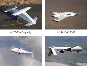
(a) X-50A Dragonfly (b) J-UCAS X-45
[image:39.595.122.477.174.445.2](c) A-160 Hummingbird (d) Predator/FINDER integration
Figure 2.2: Developmental UAV programmes.
Though highly speculative, many of the possibilities highlighted in the roadmap,
includ-ing the introduction of rotary-winclud-ing designs, combat UAVs, and interactions between
dif-ferent UAV systems can already be seen in recent developmental programmes such as
the J-UCAS combat UAV, the 5 ft FINDER mini-UAV (designed for deployment from a Predator aircraft), the A-160 Hummingbird VTOL rotary-wing UAV, and Boeing’s
Drag-onfly Canard Rotor/Wing programme (see Figure 2.2). However, the actual development
of UAV design and capabilities will be very much dependent on sudden changes in
fund-ing, political will, and military thinking. The 2005 DoD roadmap17outlined many of the
same long-term goals listed above but was less specific about the timeline. Since then, the
J-UCAS programme has been largely cancelled and the US Army has eliminated two of
the planned developmental UAVs from its Future Combat System (FCS), which has itself
undergone considerable restructuring.
civilian uses for UAVs have been mooted and many more can be easily imagined.
Fol-lowing an initial period of inertia, such uses are now beginning to emerge in the fields
of police surveillance, drug enforcement, border control, and ‘search and rescue’
appli-cations following disasters.24–27 Though demand is growing there are several regulatory,
safety, and technological obstacles that must still be overcome. However, it is possible that, in time, the commercial applications of UAVs may come to predominate over
mili-tary ones by a significant degree, just as is the case with the manned aviation market.16
2.3
The DARPA MAV Initiative
The idea of miniature flight vehicles first came to prominence in 1993 with the RAND
Corporation’s ‘Future Technology-Driven Revolutions in Military Operations’ workshop.28
Born from RAND’s interest in microsystems, the concept of ‘microdrones’ was discussed
as part of the larger topic of mobile micro-robots. Despite some initial scepticism the idea
gained momentum and, in 1995, investigations into the feasibility of micro-fliers were
conducted at MIT’s Lincoln Laboratory29, 30 and at the US Naval Research Laboratory
(NRL). Together with the RAND workshop, this activity prompted the involvement of
the Defence Advanced Research Projects Agency (DARPA) which, in 1996, instigated a
multi-year developmental programme to focus attention on this area. It is through this initiative that the commonly recognised definition of an MAV platform was established.
To justify DARPA involvement, a suitably difficult objective was deemed necessary and
so a maximum characteristic dimension of 6” was imposed. This particular choice meant that the proposed MAVs would be an order of magnitude smaller than the smallest UAV
platform in operation at the time, the 4 ft wing span SENDER aircraft operated by the
NRL. Additionally, a notional weight of 50 g, which included a day/night imaging
pay-load, was suggested and a typical mission outlined: After launch the vehicle would be
expected to fly a distance of 1 km to the designated target area where it would loiter for
30 minutes in turbulent conditions, with wind-speeds of up to 25 mph, before returning to
base. The envisaged scenario would require the vehicle to be quiet and inconspicuous yet
relatively robust, possessing of the ability to manoeuvre amongst obstacles such as trees
or buildings whilst making repeated ascents and descents from altitudes of 350 ft.
Requirements for the command module and control system were also established. The
system would be used in a squad-level combat environment so it needed to be light enough to be man-portable, simple enough to be operable by an unskilled user, and yet provide
a high degree of autonomy. Whilst not of primary concern, a desire to keep the overall
specifications remain a useful benchmark, particularly since no other agency, American or
otherwise, has provided an alternative. Whilst the DARPA parameters have since become
an accepted industry standard, the DoD has stated that “the requirements described are
neither doctrinally or technically based and are not considered immutable”.22
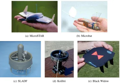
(a) MicroSTAR (b) Microbat
[image:41.595.97.502.156.435.2](c) SLADF (d) Kolibri (e) Black Widow
Figure 2.3:DARPA initiative MAV designs.
The DARPA initiative aimed to develop both fundamental flight-enabling technologies
and mission-capable system demonstrators. Research into advanced propulsion and power
systems included a Micro-Electromechanical Systems (MEMS) based micro gas turbine,
developed by MIT;31 an IGR Inc. demonstration of a very lightweight solid-oxide fuel
cell; and a very small gas turbine engine by M-DOT. A flapping-wing propulsion solu-tion was also explored, with three separate programmes, run by the California Institute of
Technology (Caltech), UCLA, and AeroVironment;32 the University of Toronto Institute
for Aerospace Studies and SRI International; and Vanderbilt University,33being funded.
Each programme employed a different approach to achieving a flapping wing action. The
Caltech design used a standard direct current (DC) motor and gear box, the SRI device
used electrostrictive polymer actuators, and the Vanderbilt device used piezoelectric
actu-ators. Of the three, Caltech’s palm-sized ‘Microbat’ ornithopter design (see Figure 2.3b)
was the more widely reported. In 2003, a 9” version of Microbat, weighing only 14 g,
Four different vehicle designs were also developed under the DARPA programme (see
Figure 2.3). Two, the Lutronix Kolibri shrouded propeller design and Microcraft’s Small
Lift-Augmented Ducted Fan (SLADF), were rotorcraft with a VTOL capability. The
SLADF could also fly horizontally by pitching over and developing lift from the
aerofoil-shaped circular duct and an optional wing. The Lockheed Sanders MicroSTAR (later acquired by BAE Systems) and AeroVironment Black Widow were both fixed-wing
de-signs. The Black Widow is particularly notable for being probably the most impressive
vehicle to emerge from DARPA’s funding of MAV research.
A (broadly) circular ‘flying-wing’ design of 6” span, the Black Widow was developed
over a four year period, passing through twenty iterations from conception to the final
vehicle.35 Made primarily from Expandable Polystyrene (EPS) foam, with balsa wood
control surfaces, the vehicle weighed approximately 60 g and was powered by lithium
batteries. In flight tests it successfully reached speeds of up to 35 mph (15 m/s), a
maxi-mum straight line range of 17 km (though communications range was limited to 1.8 km),
a maximum altitude of 769 ft, and an endurance time of 30 minutes. The Black Widow
programme was an important step in MAV development, achieving several key results and demonstrating the importance of careful design and optimisation to maximise the
ef-ficiency of both the critical, individual subsystems (such as propulsion and power) and
the entire vehicle itself. On a technological front, a basic avionics suite for an
MAV-sized craft was shown to be entirely feasible and a custom-built colour video camera plus
down-link transmitter of total mass 3 g was developed. Despite this success, little of this
technology has come into use today.
Whilst the US Army and Marines had been receptive to the basic MAV concept, the initial
phase of the DARPA programme concluded in 2000 with the general consensus that,
for the present, a 6” vehicle was unable to provide the performance capabilities sought
after by the military. The focus has now shifted to vehicles in the 8” to 16” size range,
which are better suited to existing payload and propulsion technologies. Relaxing the size
constraint brings several other benefits too. Increased size improves the aerodynamics of the lifting surfaces and allows MAVs to use more powerful telemetry transmitters with
simpler, smaller low-gain antennas. Without this, many first generation vehicles required
a large (6 ft) antenna at the ground station so as to receive the low power signals emitted
by the MAV. This resulted in the total system size, as defined by vehicle plus Ground
Control Unit (GCU), for a 15 cm craft being similar to that for a larger 100 cm vehicle,
and negated some of the advantages of developing a MAV-scale craft.2
In 2001, DARPA’s MAV programme progressed to the Advanced Concepts Technology