Fault Tolerant Control for a Modular
Generator-Converter Scheme for Direct Drive Wind
Turbines
Max A. Parker, Chong H. Ng, and Li Ran,
Senior Member, IEEE
Abstract—A modular power electronic converter, with a cas-caded H-bridge multilevel inverter, has been proposed as the grid interface for a large direct drive wind turbine generator. The present study is to investigate the potential and requirement of fault tolerant operation in such a system. As each module is connected to isolated generator coils, tolerance to a module or coil fault is possible if the affected module can be bypassed while the control of the healthy modules can be adjusted accordingly. A boost rectifier scheme on the machine side of the power conversion stage has been developed for this purpose, featuring control of the coil current without measuring the EMF. A coordinated DC-link voltage controller has been developed which can rapidly raise the DC-link voltage of the remaining modules to compensate for the loss of a module, while ignoring the ripple in the DC-link due to low-frequency inverter switching. The ability of the resultant system to tolerate module faults has been demonstrated on a small scale laboratory prototype.
Index Terms—Boost rectifier, multilevel inverter, modularity, fault tolerance, control, wind power , PM generator.
I. INTRODUCTION
T
HE concept of direct drive is attractive to the design of some large wind turbines because it eliminates the gear-box as a source of unreliability, particularly low availability. This is usually considered for turbines experiencing very cold weather which can reduce gearbox lubrication efficiency, or for those located remotely with restricted maintenance access. The use of a fully-rated converter for grid interface also provides good control and grid fault ride-through performance.Direct drive presents challenges. The need to maintain a stable air-gap in a machine of large diameter requires a heavy supporting structure with significant mass, much of which is not active [1], [2]. This, and the specialised generator design, as well as the need of a fully-rated converter lead to high system cost. The specially designed generator can also be
Manuscript received July 16, 2009. Accepted for publication February 25, 2010.
Copyright c2009 IEEE. Personal use of this material is permitted. Permis-sion from IEEE must be obtained for all other users, including reprinting/ republishing this material for advertising or promotional purposes, creating new collective works for resale or redistribution to servers or lists, or reuse of any copyrighted components of this work in other works.
Max A Parker was with the School of Engineering, Durham University and is now with the Department of Electrical and Electronic Engineer-ing,University of Strathclyde, Royal College Building, 204 George Street, Glasgow, UK, G1 1XW (e-mail: max.parker@eee.strath.ac.uk)
Chong Ng was with the School of Engineering, Durham University and is now with New and Renewable Energy Centre, Blyth, Northumberland, UK, NE24 3AG (email: chong.ng@narec.co.uk)
Li Ran is with the School of Engineering, Durham University, South Road, Durham, UK, DH1 3LE (e-mail: li.ran@durham.ac.uk)
unreliable and power electronic converter failure has been a main cause of shut-down [3], [4]. For systems which are difficult to access, e.g. offshore wind turbines, reliability is highly desired, as is fault tolerance - the ability for the turbine to work at reduced power when part of it has failed.
Several generator designs have been produced, aiming to mitigate some of the problems mentioned above [5] [6]. These include slotted, slotless and ironless designs, and feature a modular configuration. One of these is the slotless design, with individually encapsulated non-overlapping coils mounted along the air-gap, and with permanent magnet excitation. Compared with a slotted design, the air-gap closing forces are greatly reduced, allowing a much lighter supporting structure, although the generator diameter is increased to increase the peripheral speed. The use of many identical coils means that the coils can be mass produced, giving lower cost and potentially higher reliability if fault tolerance can be provided. A grid interface has been developed for such a generator, based on a modular cascaded H-bridge multilevel voltage-source inverter (CMVSI) [7], as outlined in Fig.1. The use of multilevel inverter allows a high output voltage (e.g. 11kV) while still using 1200V or 1700V switching devices, and low output voltage distortion with low device switching frequency. The cascaded multilevel inverter was shown to have a low component count among available multilevel topologies, and has the potential for a modular construction to reduce the cost and to implement fault tolerance [8].
The converter consists of a number of modules attached to the generator, each having its own DC-link. The modules are supplied by boost rectifiers, allowing the DC-link voltage to be maintained with a changing turbine speed. The boost rectifier means that a sinusoidal current can be drawn from the coil, and the magnitude of each coil current can be varied to compensate for the difference in EMF caused by generator structural eccentricity. The generator is designed to produce an 8-phase output, with 135◦ phase shift between adjacent coils; pairs of coils can be selected with 90◦ phase shift to smooth the power into the DC-link. A 3-phase input could be adopted, but would require 3 coils per module.
#b23 #b2n
#a1n
#a13
#a12
#a11
#b
1n
#b
13 #b
12
#b
11
#b 21
#b
22
#c23 #c22 #c21
#c11
#c12
#c13
#c1n
#a
21
#a 22
#a
23
#a
2n
#c 2n
N L1
L2
L3
11kV Generator
Converter modules
Generator coils
(a)
Boost rectifiers DC link Hbridge
[image:2.612.313.560.50.274.2](b)
Fig. 1. Proposed grid interface scheme. (a) Overall converter structure for 3-phases, (b) An individual converter module.
are adequately insulated from the generator structure. Each phase of the inverter has two parallel strings of modules, connected to the grid via coupling inductors which prevent large circulating currents if the switching instances of each string are slightly different.
A consequence of a generator with air-gap windings is that the coil inductance is low, requiring a high switching frequency for the rectifiers to limit the current ripple. This requirement and the desire to use cheap and easily available switching devices, mean that devices with low voltage rating are preferred, and a large number of modules will be needed to achieve a high output voltage. This is in line with the requirements of fault tolerance of the system and the waveform quality of the synthesized output voltage.
The switching strategy for the inverter is shown in Fig.2 and has been covered in detail in reference [7], whereα1−α4are the switching instants (angles) of the H-bridge inverter module. The switching strategy aims to share power between modules. The total real power is controlled by the phase difference between the inverter and grid voltages, while reactive power is controlled by the module DC-link voltages to vary the total output voltage. The DC-link can be controlled by the current demand for the input rectifiers. This system allows the DC-link voltages for all the modules to be balanced, even when the power sharing between modules is not strictly equal.
Each module contains a microcontroller, which handles the
−5Vdc
5Vdc Vout1
Vout2
Vout3
Vout4
Vout5
0V
M
od
ul
e O
ut
put
V
ol
ta
ge
s
C
om
bi
ne
d V
ol
ta
ge
Reference Waveform
1 2
[image:2.612.55.287.53.387.2]3 4
Fig. 2. Asymmetrical half cycle inverter switching scheme.
control of the boost rectifiers, and the regulation of the DC-link voltage. A distributed control architecture is proposed for the inverter, estimating the position of the grid voltage and setting the inverter output voltage accordingly to achieve the required output power [9]. In the prototype system described later, the modules communicate with each other using a CAN bus, which allows the estimated grid voltage positions of all the modules to be synchronised.
Although the basic operating principle of such a system in the steady state has been shown previously [7], the fault tolerance capability has not been demonstrated and evaluated. For the reasons that will become clearer later in this paper, fault tolerant operation relies on rectifier control which is also responsible for DC-link voltage regulation; this was assumed to be ideal in previous studies. Furthermore, it is important to coordinate the control of different modules during the fast transient and so the fast detection of a module failure is also important. This study aims to explain the requirements of fault tolerant operation and to investigate the techniques that can be used to satisfy such requirements. It is expected that the experience will also be useful to research engineers developing modular generator systems with power electronic interface for direct drive or semi-direct drive wind turbines, or other variable speed power generation applications.
II. FAULTTOLERANCECONSIDERATIONS
The high component count of the multilevel inverter may reduce the reliability compared with a standard 2-level inverter, but the introduction of fault tolerance can enable the overall availability to exceed that of an individual module [10].
Fault tolerant, modular cascaded multilevel inverters have been used, mostly for medium-voltage motor drives, with the DC-links fed from the grid through rectifiers and isolated transformer windings [11], [10], [12], [13]. In the event of a module fault, the faulty module is bypassed, and the resulting voltage imbalance is corrected by changing the phase angle between modules. The requirements for fault tolerance in the proposed system differ in several ways:
• The motor drive can operate at a reduced output voltage
after a module fault, whereas the proposed system must maintain the output voltage as this is directly dependant on the grid voltage.
• Many motor drives can briefly cease providing power while they reconfigure after the loss of a module [10]. This is undesirable in a wind turbine grid interface as the turbine speed needs to be regulated. A sudden drop in the exported power would also reduce the power quality.
• The grid interface neutral point is likely to be connected to ground in the present case in order to detect phase to ground faults, so cannot always be shifted to compensate for an unbalanced voltage output.
In the event of a module failure, the affected module must be bypassed immediately, in order for the output current to continue to flow. The exact mechanism of bypassing the module will not be considered, but IGBTs of press pack type will generally fail in short circuit. The devices in the output H-bridge inverter of a module can be all gated on to provide a bypassing short circuit upon detecting an upstream failure. It is noted that the bypassing mechanism must operate even if the module controller has failed, ideally if the controller stops sending a signal. If the module controller is still operating, then it must be able to recognise that a fault has occurred in order to activate the bypass circuit, and the means of detecting the fault depends on the nature of the fault:
• Coil and rectifier faults will result in no power being drawn from the faulty coil or rectifier, and a high current demand in the remaining coil.
• Complete failure of the DC-link capacitors will result in the voltage crashing or rising uncontrollably, depending on the nature of the failure.
• Failure of the output H-bridge devices in short circuit will result in the DC-link voltage crashing. Failure in open circuit will result in it rising.
In the test system, the module controllers are supplied by an external 12V supply, through an isolating DC-DC converter, but in a full size system they will be fed from local DC links. This means that any crash in the DC-link voltage will cause the controller to fail, triggering the bypass circuit.
The loss of a module means that the total output voltage of the inverter will drop, leading to a surge in reactive power. The drop in inverter voltage will appear to the inverter control system as a sudden rise in the grid voltage, and the modules will react by increasing the DC-link voltage so that the inverter
reactive power output is under control. Operation during a module fault indeed depends on the response of the DC-link voltage and rectifier control, which can be used to signify fault occurrence and activate the fault tolerant mode.
The loss of a module will result in the inverter producing a distorted voltage waveform, and the module switching instants must be changed accordingly, which requires the remaining modules to know the position of the failed module in the switching sequence. If the failed module still has a functioning controller, it can recognise the failure through the methods mentioned already, and broadcast a message on the CAN bus to inform the other modules. If the module controller is not functioning, then other modules can identify the sequence of the failed module by analysing the current waveform [14], or, as the modules are continuously communicating on the CAN bus, simply noticing the absence of message from the module. The latter has been adopted in this study.
III. RECTIFIERCONTROL
Control of the rectifier consists of controlling the coil current to be sinusoidal at the correct magnitude and close in phase with the coil EMF, which maximises the coil utilisation. The use of boost rectifiers allows the DC-link voltage to be varied independently of the generator speed, so that the generator speed can vary over a large range to improve power point tracking under variable wind conditions. In order to draw a coil current in phase with the coil EMF, the EMF angle and magnitude must be tracked, and this is part of the rectifier control system.
A. Rectifier Current Control
The rectifier equivalent circuit is shown in Fig.3. Each generator coil connected to the rectifier produces an EMFen
wheren= 1or 2, which is sinusoidal, and the EMFs of the two coils in the same module have a 90◦ phase shift. The use of concentrated non-overlapping coils, permitted by an increased diameter of the machine [15], means that the mutual inductance between the coils is small, and will be ignored. Consequently, only the self inductanceLand resistanceRare considered. The rectifier is PWM switched, and applies a time averaged voltage vn to the coil, which depends on the PWM
duty cycle d and the module DC-link voltage vdc according
to (1), where againn= 1or 2.
vn= (1−dn)vdcsign(in) (1)
The coil current is controlled in a voltage feedforward structure, where the sinusoidal terminal voltage necessary to achieve the desired current is calculated to predominantly set the rectifier duty cycle d1 or d2. Fig.4 shows the phasor diagram for the terminal voltageV, given the coil resistance Rand inductanceLas well as the desired currentI∗.Eis the EMF andωthe angular frequency, observed with a phaselock loop (PLL) to be described later.
L , R
L , R e1
e2
i1
i2
v1
v2
d1
d2
vdc
[image:4.612.64.281.53.172.2]ir ii
Fig. 3. Rectifier equivalent circuit
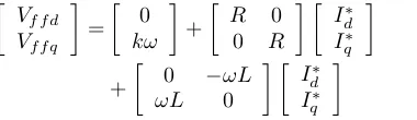
the d axis by 90◦. The voltage equation is shown in (2) where Id∗andIq∗are the desired coil currents in the rotating reference frame.Vf f d andVf f q are the feedforward coil voltages. The
EMF magnitude is proportional to the generator speed, and is estimated as E=kω, wherek is a constant.
Vf f d
Vf f q
=
0 kω
+
R 0
0 R
Id∗ Iq∗
+
0 −ωL
ωL 0
Id∗ Iq∗
(2)
The instantaneous voltages to be applied to the coils, vf f1 andvf f2, can be obtained from transformation to the stationary reference frame: e−jθ whereθis the electrical angle between the q axis and the magnetic axis of the leading coil in the module, as to be estimated. A problem with this approach is that the rectifiers used do not allow the coil current and the applied voltage to have different signs. Around zero-crossing, there is a region where the current has passed through zero, but the feedforward voltage that would need to be applied to the coil to achieve the desired current has not as implied in Fig.4. Therefore the voltage that causes the current to continue after zero-crossing in the desired trajectory cannot be achieved in this region, leading to distortion after current zero-crossing, i.e. the so-called cusp’ distortion [16]. The voltage actually applied to the coil is opposite to the desired polarity. This problem can be largely attenuated by including a current proportional control term in the module microcontroller, to generate an additional voltage demand which cancels the duty cycle associated with the feedforward voltage. In other words,
jL I* R I*
I* E
V
[image:4.612.90.280.291.346.2]d q
Fig. 4. Boost rectifier phasor diagram
if the applied voltage is to be in the opposite desired polarity, the current control will reduce the voltage, ideally to zero. The current control is implemented in the stationary reference frame, where the current reference is sinusoidal, so that its gain can be readily set to provide adequate correction following current zero-crossing but not to significantly affect the rest of the control cycle.
The proportional current controller acts on the rectifier duty cycles, after the conversion of the feedforward voltage to the stationary reference frame, and operates independently on the two coils. It can also compensate for the error in the estimated EMF position, which would otherwise lead to large coil currents flowing. The complete current control loop is shown in the top part of Fig.5, where the feedforward calculation block implements (2). The bottom part of Fig.5 is for machine EMF estimation, which is described next.
B. Machine EMF Estimation
The calculation of the feedforward voltage and the reference current for the above proportional controller requires the knowledge of the machine EMF angle θ and the machine speed. This is supplied by an observer system based on a phaselock loop (PLL), often used for EMF estimation [17], [18], [19].
In the PLL, a reference value of the EMF angle θˆ is obtained by integrating an estimation of the machine speed ˆ
ω. The instantaneous angle of the coil EMF is also calculated based on the coil current, the applied terminal voltage and the inductance and resistance parameters. This is compared with the EMF angle reference, and the phase error between the two is used to drive a loop filter, which provides the estimation of the machine speed. If the estimated EMF angle is found to lag the calculated EMF angle, the phase error will result in an increase in the estimated machine speed, until the estimated EMF angle matches the calculated angle. How quickly this happens depends on the design of the loop filter.
The complete rectifier control loop is shown in Fig.5. The machine EMF is calculated in the rotating dq reference frame at the ‘EMF Estimation’ block using (3), where E is the calculated EMF, V the voltage applied to the coil, I the coil current. V must be calculated from the rectifier duty cycles, after the proportional controller has been applied, and will be a combination of the feedforward voltage and the application of the current proportional controller.
Ed
Eq
=
Vd
Vq
−
R 0
0 R
Id
Iq
−
0 −ωLˆ
ˆ
ωL 0
Id
Iq
(3)
As the rotating reference frame used for the calculation is aligned to the estimated EMF position, the phase angle of V relative to the q-axis will give the phase error φbetween the estimated EMF and the actual EMF, and this is calculated in the EMF Estimation block and forms the input to the PLL loop filter.
EMF
Estimation Loop Filter
ej
∫
Vd
Vq
i1
i2
Id Iq
ej 1−dVdcsigni
v1
v2
d1
d2
Feedforward
calculation e
−j
Rectifier
1−∣vn∣
Vdc
Vffd
Vffq
Id*
Iq*
i1
i2
vff1
vff2
d1
d2
e−j Kp
Kp
i1*
i2 *
Id
*
Iq*
dff1
dff2
Current Control Loop
[image:5.612.48.567.54.351.2]EMF Phase Reference Loop
Fig. 5. Rectifier controller overall structure
here as it has little impact on the response of the system to module faults. The following issues must be taken into account when designing the loop filter:
• In order to avoid a steady state error in the estimated EMF angle for a constant turbine speed, the loop filter should contain an integrator.
• The bandwidth of the loop should be greater than the rotor time constant. As the rotor dynamics are non-linear, the time constant will vary depending on the conditions, between around 5s at 4m/s wind and 1.8s at 12m/s wind [20].
• The ’cusp’ distortion problem in the rectifiers results in spikes in the calculated EMF position at the current zero crossing points of the two coils, at four times the EMF frequency. In the full size turbine, the spikes will be at frequencies between 50.4Hz and 158.4Hz, and the loop filter should prevent these spikes influencing the estimated EMF.
A loop bandwidth of around 5Hz will allow the controller to track the turbine speed while providing adequate attenuation for the spikes in the calculated EMF position. In order to avoid a steady-state phase error at constant turbine speed, which would lead to an incorrect coil current, the loop filter takes the form of a proportional-integral (PI) controller.
IV. DC-LINKVOLTAGECONTROL
Control of the module DC-link voltage is complicated by the 1-phase nature of the modules H-bridge inverter, which
draws pulsating power causing significant ripple in the DC-link voltage. Each modules H-bridge is usually switched at the fundamental frequency, in an asymmetrical pattern shown in Fig.2, with the positive and negative half-cycles being switched at different times relative to the reference fundamental voltage waveform. This means that the modules DC-link voltage ripple will contain components at the grid fundamental as well as harmonic frequencies, with the levels of each harmonic depending on the modules position in the switching sequence.
Controlling the rectifier output current to keep the DC-link voltage constant can minimise the low frequency currents in the capacitors, reducing the size requirements [21]. However, this will result in the machine coil currents being modulated with the grid frequency. While the vibrations caused will balance out between the coils connected to the three phases of the converter, there will be localised stresses, which are undesirable in a generator with a lightweight flexible structure. To avoid this happening, the DC-link voltage controller cannot be allowed to react to the DC-link voltage ripple.
voltage is then used in a PI controller to determine the coil current to achieve the desired DC-link voltage, giving an overall control loop shown in Fig.6. A 20-step moving average filter, which takes the average value of the previous 20 points, sampled at 1kHz, will provide infinite attenuation at 50Hz and higher harmonics.
Controller System Filter Vdc
Vdc Vdc
*
I* V
[image:6.612.329.546.50.204.2]dc
Fig. 6. DC-Link voltage controller structure
The DC-link voltage Vdc is modelled according to (4),
whereiris the current from the rectifiers,iithe current drawn
by the inverter and C the DC-link capacitance. ir relates to
the RMS coil current demand Ic∗ using (5), where E is the rms EMF and vdcthe DC-link voltage. It is assumed that the
two coil currents in the same module are quadrature to each other so that the total power is constant.
vdc=
1 C
Z
(ir−ii)dt (4)
ir=
2Ic∗E
vdc
(5)
From a fault tolerance point of view, it is desirable for the DC-link voltage controller to have as fast response as possible. This means that the PI-controller poles and zeroes will be close to the lowest frequency zeroes of the averaging filter, and some interaction will occur. The PI controller controls the coil current demandIc∗, so due to (5) the loop gain varies with the coil EMF, i.e. with the generator speed and turbine operating condition. Because of these, the controller gains were tuned in simulation, to achieve an acceptable step response over the operating range of the turbine.
An example of the controller response to a step in the DC-link voltage demand is shown in Fig.7 for a simulated 1.8MW turbine system operating at different wind speeds. Details of the system can be found in the Appendix. A more consistent response could be obtained by having the average rectifier output current as the controlled variable, and determining the coil current demand from this using the average EMF and DC-link voltage. This was found in simulation not to result in sufficiently better performance to justify the extra complexity. Above 12m/s wind speed, the turbine speed will be held constant by controlling the pitch of the turbine blades, and the power will be the rated turbine power. In this region, the response of the DC-link voltage controller will be identical to the response at 12m/s wind speed.
V. TESTSETUP
A test system has been developed using two 2.5kW axial flux generators, driven by an induction motor and variable speed drive, through a reduction gearbox. The generators each have 12 coils, and pairs of coils can be connected to power electronic converter modules which have a 90 phase shift. The module DC-link capacitance was selected such that the
1 1.05 1.1 1.15 1.2 1.25 1.3 1.35 1.4
680 690 700 710 720 730 740 750 760 770
time (s)
Average DC Link Voltage (V)
[image:6.612.51.298.137.177.2]3m/s 6m/s 9m/s 12m/s
Fig. 7. Simulated response of the DC-link voltage controller to a step in the voltage demand
percentage voltage ripple is the same as that of a full size 1.8MW system where the capacitance was selected based on ripple current absorption.
The generators are connected to 12 converter modules. As the proposed system is based around having an inverter with a large number of levels, the modules are configured as a 25-level 1-phase inverter, producing a 230V rms output voltage for grid connection. This system is shown in Fig.8.
For the ease of access and programming, the converter modules are designed to plug into a eurocard subrack, which is mounted close to the generators. Each converter module consists of a power board, incorporating the switching devices, capacitors, gate drive and current and voltage transducers. Attached to the power board is a control board, developed around a TMS320F2808 microcontroller, which contains the peripheral devices required by the application. The control board also provides all the optically isolated communication interfaces.
Synchronisation of the module grid voltage references is carried out over a CAN bus, which provides an extremely low and deterministic message latency, and is a multi-master system where any module can communicate with any other or all the modules. This makes it ideal for the synchronisation mechanism, which is distributed between modules and requires the modules to accurately synchronise to a common time base. The modules also feature an RS485 interface, implementing the MODBUS protocol, for communication with a host PC for status monitoring and control purposes.
The inverter is connected to the grid through a relatively large 9mH coupling inductor due to the poor quality of the grid voltage waveform.
VI. EXPERIMENTALRESULTS
Converter rack
Motor
Axialflux generators
Motor drive
Grid isolation transformer and variac
(a)
Control Board 2 Rectifiers
Power Board HBridge Inverter
[image:7.612.84.265.51.323.2](b)
Fig. 8. Experimental system, featuring (a) Complete test system, and (b) Individual converter module board
R=0.345ΩandL=0.46mH. The switching frequency of the rectifier was set at 16kHz. Other system parameters are given in the Appendix.
TABLE I
TURBINE OPERATING CONDITIONS FOR EXPERIMENTAL SYSTEM
Wind Speed Generator Speed Machine Coil Output Power
(m/s) (rpm) EMF (V rms) (W)
3 (cut in) 93 5.35 32
6 142 8.17 294
9 213 12.26 994
12 (rated) 290 16.69 2500
A. Rectifier Control
Testing of rectifier control was carried out using a single power module supplied by two coils on the generator, with the output of the module connected to a resistive load. The current in the coil was measured using external probes and captured on an oscilloscope. The estimated EMF in the rotating reference frame and the estimated generator speed were recorded in the module controller and transferred using the RS485 link. The actual generator speed was obtained from the motor drive using a second RS485 link.
Results are shown in Fig.9 for wind speeds 12m/s and 3m/s. In the 12m/s condition, a good sinusoidal current is obtained. In the 3m/s condition, the current control is nearly in the discontinuous mode, and it is not possible to reduce the current any further.
The estimated generator EMF in the rotating reference frame features a ripple at four times the coil EMF frequency, due to the action of the current controller around the zero-crossing of the current. This leads to a ripple in the estimated
0 0.02 0.04 0.06 0.08 0.1 0.12 0.14 0.16 0.18 0.2
−10 −5 0 5 10
Coil Current (A)
0 0.02 0.04 0.06 0.08 0.1 0.12 0.14 0.16 0.18 0.2
−10 0 10 20 30
Estimated EMF (V)
0 0.02 0.04 0.06 0.08 0.1 0.12 0.14 0.16 0.18 0.2
280 285 290 295 300
time (s)
Generator Speed (rpm)
Estimated Speed Actual Speed
q−axis d−axis I coil1 I coil2
(a)
0 0.05 0.1 0.15 0.2 0.25 0.3 0.35 0.4
−2 −1 0 1 2
Coil Current (A)
0 0.05 0.1 0.15 0.2 0.25 0.3 0.35 0.4
−5 0 5 10
Estimated EMF (V)
0 0.05 0.1 0.15 0.2 0.25 0.3 0.35 0.4
85 90 95 100 105
time (s)
Generator Speed (rpm)
I coil1 I coil2
q−axis d−axis
Estimated speed Actual speed
(b)
Fig. 9. Rectifier current waveform and EMF tracking at (a) 12m/s wind condition, (b) 3m/s wind condition
generator speed in both of the conditions tested. The lower current with 3m/s wind speed also leads to a greater level of noise in the estimated generator speed. The calculated feedfor-ward voltage and instantaneous current demand were fetched from the tested module using the RS485 link, and subject to a spectrum analysis. The spectra showed little fourth harmonics, indicating that the generator speed estimation ripple is not having a significant effect.
B. DC-Link Voltage Control
[image:7.612.58.288.440.497.2]demand was then stepped from 27.1V to 29.6V, which is equivalent to the needed response of a healthy module to the loss of a single module when the multilevel inverter is connected to a 230V 1-phase grid. The DC-link voltage and current in one coil were recorded using a digital storage oscilloscope. The measured DC-link voltage, after averaging filter, was recorded in the module controller.
The step response of the system in 12m/s and 3m/s wind speed conditions is shown in Fig.10, and shows a fast response to the voltage demand, with some overshoot. The filtered DC-link voltage response for all four conditions listed in Table I is shown in Fig.11, and indicates a strong correspondence with the simulated step response previously shown in Fig.7.
DC-Link Voltage
Coil current
(a)
DC-Link Voltage
Coil current
(b)
Fig. 10. Response to a step in DC-link voltage demand at (a) 12m/s wind speed condition, (b) 3m/s wind speed condition
minimum coil current, due to the transition to the discon-tinuous mode, affects the response of the DC-link voltage in the 3m/s wind speed condition, making the voltage settle more slowly after the overshoot in the response. If the coil current demand is below zero then the rectifier controller will switch to a mode where short pulses are applied to the rectifier, in order to track the coil EMF with minimum current drawn. In this state, the DC-link voltage is controlled by using a resistor to dissipate power and reduce the voltage, and this state is triggered briefly in the 3m/s wind condition, after the initial overshoot.
0 0.05 0.1 0.15 0.2 0.25 0.3 0.35 0.4
27.5 28 28.5 29 29.5 30 30.5 31
time (s)
Filtered DC−Link Voltage (V)
[image:8.612.329.545.51.205.2]3m/s 6m/s 9m/s 12m/s
Fig. 11. Response of the system to a step in DC-link voltage demand
C. Fault Tolerance
As analyzed in the introduction, tolerance of module faults has two main requirements for the module controllers. Firstly the remaining modules must quickly increase their DC-link voltages to compensate for the lost module and maintain the same overall fundamental voltage. Secondly the switching instants of these modules must be changed to compensate for the lost module, and maintain a smooth AC voltage waveform. These require identifying the failed module.
These requirements were tested. Each module controller has a lookup table, containing the switching instants for all modules, and it selects its own switching instants based on the module address. Compensation for a lost module involves a second lookup table containing the switching instants for a system with one module missing. If the modules are told which one is faulty, then they can re-assign their module addresses and calculate the new switching instants based on the second lookup table, which are determined to equalize power sharing between modules before and after the fault.
The lookup tables for 12 and 11 module operation are shown in Table II, which gives the switching anglesα1 andα2from Fig.2. Switching anglesα3andα4are obtained using (6) and (7) respectively.
TABLE II
MODULESWITCINGINSTANCES
Module 12 Modules 11 modules
Number α1 (rads) α2(rads) α1(rads) α2 (rads)
1 0.041 1.777 0.046 1.874
2 0.125 2.070 0.137 2.100
3 0.210 2.225 0.229 2.259
4 0.296 2.353 0.324 2.392
5 0.385 2.466 0.422 2.510
6 0.477 2.569 0.524 2.618
7 0.573 2.665 0.632 2.720
8 0.676 2.757 0.750 2.818
9 0.789 2.846 0.883 2.913
10 0.917 2.932 1.042 3.005
11 1.072 3.017 1.268 3.096
12 1.365 3.101
α3= 2π−α1 (6)
The system was tested for fault tolerance with grid connec-tion, using a digital storage oscilloscope to capture and record the inverter output voltage and current. One module was made to enter a fault condition using the RS485 communication link, in which the lower two devices of the H-bridge are held on, and the upper devices off to emulate the action of the bypass circuit. The module also ceases communications on the CAN bus. A system to detect the faulted module has not been implemented, so to allow the remaining modules to reconfigure their switching times, the address of the faulted module was sent by the host PC using the RS485 link.
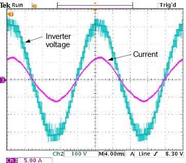
The grid and inverter voltage as well as the inverter output current waveforms, in the 9m/s wind speed condition with no module faults, are shown in Fig.12a. The distortion in the current waveform is due to significant distortion of the grid voltage in an office building as shown in the figure. The waveforms after the fault of a single module, with the DC-link voltages of the remaining modules raised to keep the overall voltage magnitude constant, are shown in Fig.12b. The dis-tortion in the inverter voltage waveform leads to spikes in the current waveform. The waveforms after the inverter switching instants have been updated to compensate for the lost module are shown in Fig.12c. The inverter voltage waveform is now smooth, and additionally the spikes in the current waveform, shown previously, are removed.
To demonstrate that a distortion-free current waveform can be produced, even with a distorted grid voltage, a switching strategy based on phase-shifted PWM was implemented. A feedforward voltage was calculated based on the desired real and reactive power output, and a proportional controller used to force the current to follow a sinusoidal waveform. This is similar to the system used in the rectifier current controller. Fig.13 shows the test results in the 9m/s wind speed condition. It is clear that3rdharmonic is now largely absent in the current
waveform.
Testing of the dynamic reaction of the system to a module fault was also carried out. The inverter voltage and current were logged as a data file using a digital storage oscilloscope, while the DC-link voltage of one module was recorded on the module controller, along with the voltage demand, and downloaded over the RS485 link. The tests were carried out at the 9m/s wind speed condition, with a grid connection, and the module fault was set to occur at the peak of the inverter voltage waveform.
The response over a longer time scale is shown in Fig.14, with the module fault occurring at a time of 40ms. The distributed controllers for the inverter, estimating the grid voltage from the current and module output voltage, interpret the loss of a module as a sudden rise in the grid voltage, and increase the link voltage demand accordingly. The DC-link voltage controller is able to react as fast as this change in the voltage demand, and the DC-link voltage is rapidly raised to the new value. In this test, the restoration of the multilevel inverter output voltage was achieved in less than two fundamental cycles. The ability of the DC-link voltage controller and the grid voltage magnitude estimator to rapidly adjust to the loss of a module means that the magnitude of the inverter current is not to be significantly affected by the
Inverter voltage
Current Grid
voltage
(a)
Inverter voltage
Current Grid
voltage
(b)
Inverter voltage
Current Grid
voltage
(c)
Fig. 12. Inverter current and voltage waveforms at 9m/s wind condition, with (a) normal operation, (b) single module fault, uncorrected, (c) single module fault, corrected
loss of the module.
[image:9.612.344.529.44.583.2]Inverter voltage
Current
Fig. 13. Inverter current and voltage waveforms at 9m/s wind condition with active harmonic distortion correction
0 0.02 0.04 0.06 0.08 0.1 0.12 0.14 0.16 0.18 0.2
−500 0 500
Inverter Output Voltage (V)
0 0.02 0.04 0.06 0.08 0.1 0.12 0.14 0.16 0.18 0.2
−10 −5 0 5 10
Inverter Output Current (A)
0 0.02 0.04 0.06 0.08 0.1 0.12 0.14 0.16 0.18 0.2
26 28 30 32
time(s)
DC−Link Voltage(V)
[image:10.612.85.266.51.210.2]DC−link voltage DC−link voltage demand
Fig. 14. Response of the system to a single module failure
expensive system than that with a lower level of fault tolerance. The 1.8MW full size system, as summarized in the Appendix, was designed based on being able to lose 2 modules out of a string of 13, which would require the module DC-link voltage to increase by about 18%.
VII. CONCLUSIONS
The study shows that fault tolerance can be achieved with the proposed system configuration and control strategy, but a series of requirements must be met. There must be means to detect fault occurrence and identify the position of the failed module which should then be bypassed. Several fault detection methods are analyzed and one is tested based on monitoring the DC-link voltage. In most faults which cause the DC-link of affected module to collapse, the output H-bridge inverter is naturally bypassed by gating on all the switching devices when the DC-link voltage is already very low, near zero. Additional bypassing arrangement, such as a typical snubbed anti-parallel thyristor pair, would be needed for open-circuit faults of the H-bridge inverter which would be rare if press pack IGBT devices are used in large scale systems.
Fault tolerant operation also puts requirements on the dynamic control of the module DC-link voltages and the
switching instants of the H-bridge inverters. The DC-link voltages of the remaining modules can be quickly increased and stabilized using the boost rectifier, to hold the reactive power output constant. The switching instants of the H-bridge inverters can be updated to constrain the harmonic content in the output voltage. Experiments have been carried out on a scaled down system to show the control performance of the system with respect to the fault tolerance requirements. It is expected that the experience gained in the study will be useful to engineers developing modular generator systems with power electronic interface for direct drive or semi-direct drive wind turbines, or other variable speed generation applications.
APPENDIX
TABLE III
SYSTEMPARAMETERS
Parameter Full Size Prototype
Phases 3 1
Strings per phase 2 1
Modules per string 13 12
Rated Power 1.8MW 2.5kW
Minimum Power 23.6kW 32W
Phase Voltage 6350V 230V
Rated String Current 47.2A 10.9A
Rated Speed 22.1rpm 290rpm
Minimum Speed 7.1rpm 93rpm
Rated Coil EMF 393V 16.69
Minimum Coil EMF 126V 5.35V
Rated Coil Current 26.7A 6.2A
Minimum Coil Current 1.2A 0.25A
Coil Inductance 8.2mH 0.46mH
Coil Resistance 0.345Ω 0.264Ω
Rectifier Switching Frequency 4kHz 16kHz
Average DC-link voltage 691V 27.1V
DC-link capacitance 1666µF 8800µF
Grid Coupling Inductance 20mH 9mH
REFERENCES
[1] H. Hansen, L, L. Helle, E. Blaabjerg, S. Ritchie, H. Munk-Nielsen, P. Bindner, P. Sorenson, and B. Bak-Jensen, “Conceptural survey of generators and power electronics for wind turbines,” Risø National Laboratory, Roskilde, Denmark, Tech. Rep., 2001.
[2] A. S. McDonald, M. A. Mueller, and H. Polinder, “Comparison of generator topologies for direct-drive wind turbines including structural mass,” in Proceedings of the International conference on Electrical Machines (ICEM06), Chania, Crete, Sep. 2006.
[3] P. J. Tavner, G. J. W. van Bussel, and F. Spinato, “Machine and converter reliabilities in wind turbines,” inIEE 2nd International Conference on Power Electronics, Machines and Drives (PEMD), Dublin, 2006. [4] W. Yang, P. J. Tavner, C. J. Crabtree, and M. Wilkinson, “Cost-effective
condition monitoring for wind turbines,” vol. 57, no. 1, pp. 263–271, 2010.
[5] E. Spooner, P. Gordon, J. R. Bumby, and C. D. French, “Lightweight ironless-stator PM generators for drect-drive wind turbines,”IEE Proc. Electr. Power Appl., vol. 152, no. 1, pp. 17–26, 2005.
[6] Z. Chen and E. Spooner, “A modular, permanent-magnet generator for variable speed windturbines,” in Seventh international conference on electrical machines and drives, Durham, UK, 1995, pp. 453–457. [7] C. H. Ng, M. A. Parker, L. Ran, P. J. Tavner, J. R. Bumby, and
E. Spooner, “A multilevel modular converter for a large, light weight wind turbine generator,”IEEE Trans. Power Electron., vol. 23, no. 3, pp. 1062–1074, May 2008.
[image:10.612.337.537.223.446.2][10] P. W. Hammond, “Enhancing the reliability of modular medium voltage drives,”IEEE Trans. Ind. Electron., vol. 49, no. 5, pp. 948–954, 2002. [11] ——, “A new approach to enhance the power quality for medium voltage
drives,”IEEE Trans. Appl. Ind., vol. 33, no. 1, pp. 201–208, 1997. [12] J. Rodriguez, P. Hammond, J. Pontt, R. Musalem, P. Lezana, and M. J.
Escobar, “Operation of a medium-voltage drive under faulty conditions,”
IEEE Trans. Ind. Electron., vol. 52, no. 4, pp. 1080–1085, 2005. [13] P. Lezana and G. Ortiz, “Extended operation of cascaded multicell
converters under fault conditions,”IEEE Trans. Ind. Electron., vol. 56, no. 7, pp. 2697–2703, 2009.
[14] P. Lezana, R. Aguilera, and J. Rodriguez, “Fault detection on multicell converter based on output voltage frequency analysis,”IEEE Trans. Ind. Electron., vol. 56, no. 6, pp. 2275–2283, 2009.
[15] J. R. Bumby, R. Martin, E. Spooner, N. L. Brown, and B. J. Chalmers, “Electromagnetic design of axial flux permanent magnet machines,”IEE Proc. Electr. Power Appl., vol. 151, no. 2, pp. 151–160, 2004. [16] D. Van de Sype, K. DeGusseme, A. Van de Bossche, and A. Melkebeek,
“Duty-ratio feedforward for digitally controlled boost PFC converters,”
IEEE Trans. Ind. Electron., vol. 52, no. 1, pp. 108–115, 2005. [17] L. Harnefors and H. Nee, “A general algorithm for speed and position
estimation of AC motors,”IEEE Trans. Ind. Electron., vol. 47, no. 1, pp. 77–83, 2000.
[18] R. M. Santos Filho, P. F. Seisax, P. C. Cortizo, L. A. B. Torres, and A. F. Souza, “Comparison of three single-phase PLL algorithms for UPS applications,”IEEE Trans. Ind. Electron., vol. 55, pp. 2875–2884, 2009.
[19] E. Lavopa, P. Zanchetta, M. Sumner, and F. Capertino, “Real-time estimation of fundamental frequency for active shunt power filters in aircraft electrical systems,”IEEE Trans. Ind. Electron., vol. 56, no. 8, pp. 2875–2884, 2009.
[20] W. E. Leithead and B. Connor, “Control of variable speed wind turbines: Dynamic models,”Int.J. Control, vol. 73, no. 13, pp. 1173–1188, 2000. [21] J. Espinoza, M. Perez, J. Rodriguez, and P. Lezana, “Regenerative medium-voltage ac drive based on a multi-cell arrangement with mini-mum energy storage requirements,”IEEE Trans. Ind. Electron., vol. 52, no. 1, pp. 171–180.
Max Parker received his Engineering Doctor (Eng.D.) degree in Power Electronics, Drives and Machines from the University of Newcastle Upon Tyne, UK, in 2009, with research carried out in the School of Engineering, Durham University and sponsored by the New and Renewable Energy Centre (NaREC) in Blyth, UK. He is currently working as a research fellow with the Institute for Energy in the Environment at the University of Strathclyde, Glasgow, UK, investigating the feasibility of large offshore wind turbine designs. His research interests include digital control of power electronic systems, particularly fault tolerant multilevel converters, and distributed control systems.
Chong Ng received his Ph.D. degree in engineer-ing from Northumbria University, Newcastle Upon Tyne, UK. He was an R&D Engineer with Lambda Power in Singapore before joining as a post-doctoral Research Associate in the New and Renewable En-ergy Group (NaREG), Durham University, UK in 2005. During the employment he was responsible for a wind energy conversion research project, that was funded by the EPSRC, and involved in several others renewable energy related research projects. He is currently a Senior Electrical Design Engineer in the New and Renewable Energy Centre (Narec) in Blyth, UK. His research interests include the application of power electronics in large scale renewable energy systems and small scale embedded generator systems.