City, University of London Institutional Repository
Citation
:
Kerrouche, A., Boyle, W. J. O., Gebremichael, Y., Sun, T., Grattan, K. T. V.,
Taljsten, B. and Bennitz, A. (2008). Field tests of fibre Bragg grating sensors incorporated
into CFRP for railway bridge strengthening condition monitoring. Sensors and Actuators A:
Physical, 148(1), pp. 68-74. doi: 10.1016/j.sna.2008.07.014
This is the accepted version of the paper.
This version of the publication may differ from the final published
version.
Permanent repository link:
http://openaccess.city.ac.uk/14968/
Link to published version
:
http://dx.doi.org/10.1016/j.sna.2008.07.014
Copyright and reuse:
City Research Online aims to make research
outputs of City, University of London available to a wider audience.
Copyright and Moral Rights remain with the author(s) and/or copyright
holders. URLs from City Research Online may be freely distributed and
linked to.
City Research Online:
http://openaccess.city.ac.uk/
publications@city.ac.uk
Field tests of fibre Bragg grating sensors incorporated into CFRP for railway
bridge strengthening condition monitoring
A. Kerrouche
a,∗, W.J.O. Boyle
a, Y. Gebremichael
a, T. Sun
a, K.T.V. Grattan
a, B. Täljsten
b, A. Bennitz
caSchool of Engineering and Mathematical sciences, City University London, London, EC1V 0HB, United Kingdom bDepartment of Civil Engineering, Technical University of Denmark, Denmark
cLulea University of Technology, Sweden
Keywords:
Fibre Bragg grating (FBG)
Carbon fibre reinforced polymer (CFRP) Strain measurement
Bridge strengthening
a b s t r a c t
The EU is in the process of upgrading the national railway networks to meet the demands from high-speed passenger trains and heavy Freight traffic. This upgrade necessitates a review of the development and implementation of novel technologies to repair and strengthen the existing bridge structures and to improve their performance.
This paper presents the evaluation results of the use of FBG strains sensors incorporated in CFRP (carbon fibre reinforcement polymer) rods and tubes as part of the methodology for monitoring the performance of the NSMR (near surface mounted reinforcement) which is an essential part of the repair and strengthening of bridges. In addition, a new method has been tested for the first time using CFRP tubes which calls for the drilling of holes instead of sawing grooves in the installation process.
The paper discusses in some detail the strengthening mechanism, FBG sensor implementation and the electronic system used to interrogate the FBG sensors. The results obtained from the monitoring show that FBG sensors can be integrated into CFRP and that reliable measurements can be made. However, in this particular project, the strain loading is very moderate so consequently the strain levels are in the elastic regime.
1. Introduction
Over the last few decades, rail transport has become one of the most effective means of transporting passengers and goods. According to recent statistics, the number of passengers will have doubled within 10 years while then the volume of goods transported by rail will be tripled. This puts major pressure on infrastructure and innovative bridge repair techniques hence the use of restoration and strengthening methods has been increased dramatically, responding to the sudden rise of the axel load and the implementation of faster trains.
Previously, strengthening has been undertaken by the use of additional reinforced concrete but over the past few years, the use of bonded fibre composites (CFRP) has been growing as a more effec-tive means to strengthen several structures, as shown in laboratory studies[1,2]and in some field tests[3–5].
The work reported in this paper relates to the development of innovative techniques for mounting the sensor system on the bridge under consideration and consists of cutting a groove into
∗ Corresponding author. Tel.: +44 20 7040 3888; fax: +44 20 7040 8568.
E-mail address:abdel.kerrouche.1@city.ac.uk(A. Kerrouche).
the concrete surface, putting the carbon fibre reinforcement poly-mer (CFRP) rod into this groove and then covering the rods with epoxy to ensure that effective and representative measurements can be made from the structure. In addition, a new method has been tested for the first time using CFRP tube (cylinder with a hol-low centre for cable connections of electrical strain gauges and to be fully filled by epoxy upon completion of all installation) which calls for the drilling of holes instead of sawing grooves in the installation process.
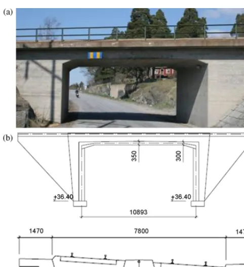
A 50-year-old railway bridge, shown inFig. 1, is located in Frövi, Sweden and is of great importance to the regional Freight traffic. Yet it is just another one of hundreds of similar bridges in Sweden, built with a service life expectancy of 50 years in the middle of the last century. By strengthening this type of bridge structure, the effective costs and the expenses for keeping the railway network running can be levelled out over several decades. Such benefits have attracted attention from Banverket (The Swedish Rail Admin-istrators), who has already co-operated in several field applications where CFRP (carbon fibre reinforced polymers) have come into use.
Fig. 1. The Frövi bridge: (a) picture of the bridge; (b) side view and cross section.
and deflections, were undertaken to understand the behaviour of the bridge before and after strengthening.
City University has been engaged to measure strain in the structure using an eight-channel FBGS (fibre Bragg grating sensor) system embedded into the CFRP rod and tube and to compare the measurements with those obtained from electrical sensors (LTU). In this way an assessment of the efficacy of the techniques and a comparative view of the performance of the FBGS system before and after could be made. In this paper the sensor placement, pro-tection procedure and the results obtained from the FBG sensors are reported.
2. Bridge strengthening
To secure a good quality of the strengthening, an epoxy resin is used to make a good bonding between the CFRP and the concrete. Two different methods of strengthening with CFRP have been used in this project. One is the effective technique of NSMR (near sur-face mounted reinforcement), and CFRP tubes technique which has never been used in field test before. NSMR is used to strengthen the lower part of the bottom slab while the tubes are used in the upper part.
2.1. NSMR rod
NSMR rods consist of CFRP bars (non-metallic, non-magnetic, non-corrosive and high strength materials) with rectangular (10 mm×10 mm) cross sections, slightly rounded in the corners to reduce stress concentrations. When produced they are covered with a protective coating-“peel-ply”, which secures the cleanness of the bar, thus also securing a good bonding to the epoxy used. NSMR is by now a reliable and accepted method. More about its abilities can be read in for example[4].
[image:3.637.317.559.65.365.2]Strengthening using CFRP rods necessitates the grooves to be cut on the underside of the bridge to adhere the rods which are covered by the epoxy as shown inFig. 2.
Fig. 2.(a) Grooves already cut underside of the bridge; (b) putting the rods into the
grooves and gluing with epoxy.
2.2. Tube
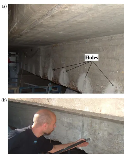
In this field test, a new strengthening technique was accom-plished using a new type of CFRP which is based on tubes (never been tested in-situ before) and they were applied for the first time on the Frövi bridge. It is related to the NSMR system in the sense of good bonding behaviour and protection against mechanical dam-ages but the placement in the structure is different. Instead of being bonded into sawn grooves in the surface of the concrete the tubes are placed in drilled holes running through the structure (Fig. 3).
By not limiting the strengthening to near surface applications it is possible to fulfil a completely new type of needs. Typically the tubes used have an outer diameter of 32 mm and a material thickness of 4 mm. These dimensions might be altered but is limited by the drilling process.
3. FBG sensors implementation
3.1. FBG concept
Fibre Bragg grating (FBG) is written and formed into a pho-tosensitive optic fibre by modulating the core refractive index periodically using interference pattern created by ultra violet lights through a phase mask[6].
When a broadband light transmits through the optic fibre, the FBG written in the core reflects back a wavelength (B) depending on the Bragg conditionB= 2newhereneis the effective
Fig. 3.(a) Holes grilled into the bridge; (b) inserting the tubes into the structure.
Fig. 4.The schematic diagram of a FBG.
the monitoring system is to identify this wavelength shift as a function of strain or temperature.
The FBG sensors used for this application are 10 mm long with a reflectivity of more than 90% and bandwidths of 0.2 nm. Previous laboratory experiments proved an applied strain of 1εequivalent to a wavelength shift of 1.24 pm and a temperature change of 1◦C induces a shift of 10 pm.Fig. 4depicts a schematic of FBG written into an optic fibre and the reflection spectrum from the FBG which has a Gaussian peak profile.
FBG sensors are widely used for several applications such as structural health monitoring due to its immunity to
electromag-Fig. 5.Schematic approach to sensor mounting (a) putting the optical fibre to the
rod; (b) putting the optical fibre to the tube.
netic interference, high resolution, large measurement range and small physical size compared to conventional strain gauges which render easy installation into the structure as well as carbon fibre reinforced polymer (CFRP) composite[6–10].
3.2. Installation of sensors into rod and tube
The work presents an excellent opportunity to monitor the strain on the bridge after the strengthening procedure had been carried out. To do so a groove of about 2 mm width and 1 mm depth was cut into the centre of a rod and of a tube in order to accom-modate the optical fibres, this forms the ‘backbone’ of the optical network containing the sensors. Two optical fibres, carrying seven FBG sensors each were glued into the actual grooves with low vis-cosity cyano-acrylate and then were covered with epoxy as shown schematically inFig. 5. The rod and the tube were placed into the structure to monitor the bridge.
3.3. Sensors location
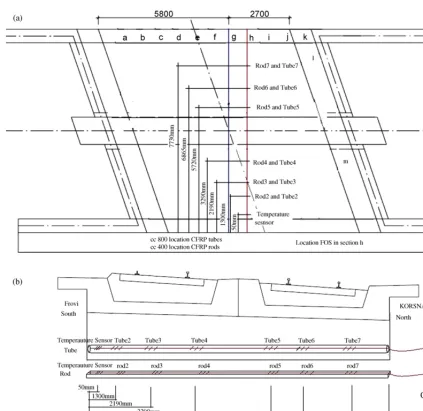
[image:4.637.36.282.392.493.2]The strengthening operation required the installation of the rods and tubes in several sections of the bridge. The rods and tubes were placed parallel to each other at 11 positions (A–K) (Fig. 6a). Electrical sensors were placed in section G while the optical sensors were placed in what is termed section H of the bridge.
[image:4.637.36.553.667.747.2]Table 1andFig. 6b shows the location of sensors within rod and tube. In fact, the sensors (Rod2, Rod3, and Rod4) in the rod and sensors (Tube2, Tube3 and Tube4) in the tube were put on the south part of the bridge, under side slab towards Frövi (south). The rest of the sensors were placed on the north part of the bridge, under side towards Korsnäs (north).
Table 1
Placement of the FBG sensors
Sensors FBG wavelengths (nm) Type Placement Position (mm)
Temperature sensors 1527.9 CFRP rod/tube Towards Frövi 50
Rod2/Tube2 1531.95 CFRP rod/tube Towards Frövi 1300
Rod3/Tube3 1542.55 CFRP rod/tube Towards Frövi 2190
Rod4/Tube4 1547.15 CFRP rod/tube Towards Frövi 3290
Rod5/Tube5 1552.05 CFRP rod/tube Towards Korsnäs 5720
Rod6/Tube6 1557.20 CFRP rod/tube Towards Korsnäs 6865
Fig. 6.(a) Schematic of the sensor placement in section H of the bridge. (b) Cross sectional view of the sensor placement into the rod and tube.
4. The monitoring system
The instrument used in this field test is a compact system, which is able to interrogate eight optical fibre channels with eight sen-sors per channel, for high level strain measurements. FBG system allowed for strain measurement to be taken from seven sensors in both the rod and tube after they were placed in the structure, as described. Furthermore, a suitable programming could be used to interrogate many more sensors per channel over smaller measure-ment ranges[11,12].
The multiplexed FBG sensor interrogation unit is utilizing a 10 mW broadband SLED (super-luminescent light emitting diode source) (centred at 1550 nm) with a spectral width of 40 nm across the C-band. The broadband source was driven by a stabilized cur-rent source using a feedback controlled thermo-electric circuit to ensure good output power stability of spectral profile, this avoids any thermal drift and damage to the device. The SLD source used proved to be stable (wavelength and intensity) during all tests.
As shown in Fig. 7, the FBGS interrogation system used in this work is based on wavelength division multiplexing (WDM) in which an array of serially connected sensors via a Fabre-Perot Spectrometer sweeps over the wavelengths of the gratings in the
array. The reflected signal from each channel is detected by one of the eight low noise (30 dB SNR) pin diode detectors. The detec-tor circuits which were developed consist of a two stage electronic circuits comprising a trans-impedance amplifier that converts the current from the optical signal to a voltage signal and then is amplified and filtered to a limiting frequency of 10 kHz to reduce noise.
[image:5.637.323.553.609.728.2]Fig. 8.Electrical strain gauge measurement when the Regina train passes the bridge.
The signals from the eight channels which have a Gaussian peak profile are sent to a digital signal processor (DSP) board named ADwin-Gold-16 based on SHARC DSP processor with local mem-ory for fast data acquisition (conversion time of 10s). The DSP board consists of two ADCs (analogue to digital converters) to con-vert analogue signals from detectors to digital signals. The DSP uses a proprietary real-time software language (ADbasic) to deter-mine the Bragg wavelengths which have previously been calibrated against the strain in the system and produces a synchronous ana-logue signal to control the scanning of the Fabry-Perot filter (used for wavelength determination). The DSP identifies the peak posi-tion of each sensor from the eight channels thus the optical spectra received are in real-time for every scan of the Fabry-Perot fil-ter.
The wavelength data were calibrated against two thermally sta-bilized (0.15 pm) reference gratings, which rejected common mode noise and provided absolute wavelength scaling. Long-term test results showed good linearity and repeatability of <10over the test period with a precision of±5and a resolution of±1 compared to foil gauge sensors within±4.
5. Load tests and results
In this particular set of experimental tests, which was held in Frövi, Sweden, the major objective was to monitor the bridge by measuring parameters such as strain, displacements and crack opening size after the strengthening, using several methods and techniques, discussed above. The strain level variation has been monitored for two days, using the eight-channel FBGs system described earlier. The effects on the bridge of two different types of trains were monitored in this test – the trains used were a passenger train (namely the Regina train consisting of two car-riages) and a Freight train (that has different load capacities and speeds.
5.1. Results from the tube
Cross-calibration carried out using the electrical strain gauge sensors that had previously been mounted showed that Regina and Freight trains reached a strain level of approximately up to±5
[image:6.637.40.279.65.216.2]when it passed over the bridge (seeFig. 8). The FBG system used in this test is limited to a measurement rate of 5/Hz (∼5 mea-surements per second) due to a combination of the measurement accuracy of the Fabry-Perot system and the use of LabView-based peak position detection algorithm. Therefore, it was impossible to distinguish the effect of any trains induced strain level from the noise floor signal.
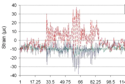
Fig. 9.Strain measurement when Freight train passes the bridge.
5.2. Results from the rod
During the two days of measurement, the FBG system was able to detect only Freight trains when it passes through the bridge as shown inFig. 9with a signal to noise ratio SNR of approximately 4.15.
The strain measurement also depends on which side (northern or southern) of the bridge over which the train passes, in addi-tion to the weight and the speed of the Freight trains used in the test. InFigs. 10 and 11, a sample reading of the observed strain measurement data on the rod when only one Freight train passes the southern and the northern tracks has been shown respectively without a measurement from the sensor Rod2 (1531.95 nm). This unexpected result may be due to the fact the sensor has been bro-ken during the installation process and therefore no measurement would be possible.
Before strengthening, strain distribution in the transverse steel reinforcement and deflection of the bridge have been detected to fully understand the mechanisms of the bridge and alternatively to compare the measurements afterwards.[13]
The strain level appears to show a reduced value compared to previous measurements taken before the strengthening.
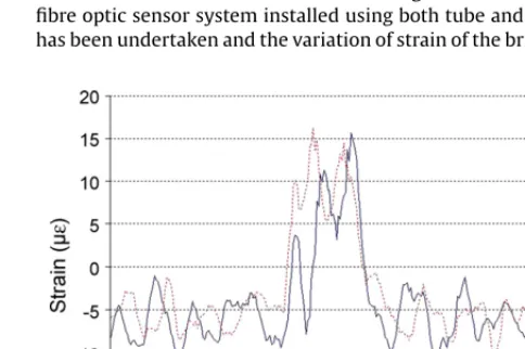
6. Discussion
A series of tests of the strain of a strengthened bridge using a fibre optic sensor system installed using both tube and rod CFRPs has been undertaken and the variation of strain of the bridge under
[image:6.637.307.549.567.728.2]Fig. 11.Strain levels when Freight train passes the northern track.
a range of strain conditions arising from Freight trains has been recorded during the two days of measurement and reported in this paper. The actual measurement of the strain falls within the range of−45to +25.
As mentioned before, the strain level in the tube was 3in which case this measurement falls within the baseline noise. There-fore, it was impossible to distinguish the actual strain from the noise.
In this particular project it was not possible to use a “reference train” with a known weight to compare the results from the moni-toring before and after strengthening. However, the strengthening is carried out for the ultimate limit state whereas the monitoring is done in the service limit state.
The conclusion is that the strengthening procedure was a suc-cess but the monitoring needs more thorough evaluation before clear conclusions can be drawn.
Acknowledgements
This test was fully supported by Sustainable Bridges Project funded by EU FP6 through the collaboration between City Univer-sity and Lulea UniverUniver-sity Sweden. The authors would like to thank the Swedish Rail Administration, Banverket for their support dur-ing the test project. Infrastructure support from the UK Engineerdur-ing & Physical Sciences Research Council (EPSRC) is also acknowledged.
References
[1] Waterfront Repair and Upgrade, Advanced Technology Demonstration Site No. 2: Pier 12, NAVSTA San Diego, Site Specific Report SSR-2419-SHR, Naval Facilities Engineering Service Center, Port Hueneme, CA, Warren, 1998.
[2] X. Yan, B. Miller, A. Nanni, C.E. Bakis, Characterization of CFRP bars used as ear-surface mounted reinforcement, in: M.C. Forde (Ed.), Proceedings 8th Inter-national Structural Faults and Repair Conference, vol. 10, Engineering Technics Press, Edinburgh, Scotland, 1999 (CD-ROM version).
[3] D.R. Mertz, J.W. Gillespie Jr., Rehabilitation of Steel Bridge Girders Through The Application Of Advanced Composite Materials, Transportation Research Board, Washington, DC, 1996 (Contract NCHRP-93-ID011).
[4] B. Täljsten, A. Carolin, H. Nordin,) Concrete Structures Strengthened with Near Surface Mounted Reinforcement of CFRP, Advances in Structural Engineering, vol. 6, Number 3, August 1, 2003, pp. 201–213.
[5] T. Hogue, R.C. Cornforth, A. Nanni, Myriad convention center floor system reinforcement, in: C.W. Dolan, S. Rizkalla, A. Nanni (Eds.), Proceedings of the FRPRCS-4, ACI, Baltimore, MD, 1999, pp. 1145–1161.
[6] K.T.V. Grattan, B.T. Meggitt (Eds.), Optical Fiber Sensor Technology: Advanced Applications, Kluwer, Dordrecht, The Netherlands, 2000, pp. 79–187. [7] K.T.V. Grattan, B.T. Meggitt, Optical Fiber Sensor Technology: Fundamentals,
Kluwer, Norwell, MA, 2000.
[8] E. Udd, Fiber optic smart structures, Proc. IEEE 84 (1) (1996) 60–67.
[9] W. Boyle, F. Kerrouche, J. Leighton, Guidelines and current developments for the use of fibre Bragg grating sensors in the rail industry. Sustainable
bridges: assessment for future traffic demands and longer lives, Dolnoslaskie Wydawnictwo Edukacyjne (2007) 169–180.
[10] Y.M. Gebremichael, W. Li, W.J.O. Boyle, B.T. Meggitt, K.T.V. Grattan, B. McKinley, G.F. Fernando, G. Kister, D. Winter, L. Canning, S. Luke, Integration and assess-ment of fibre Bragg grating sensors in an all-fibre reinforced polymer composite road bridge, Sens. Actuators A 118 (2005) 78–85.
[11] Y.M. Gebremichael, W. Li, B.T. Meggitt, W.J.O. Boyle, K.T.V. Grattan, B. Mckinley, F. Boswell, K.A. Arnes, S.E. Aasen, B. Tynes, Y. Fonjallaz, T. Triantafillou, A Field deployable, multiplexed Bragg grating sensor system used in an extensive high-way bridge monitoring evaluation tests, IEEE Sens. J. 5 (3) (2005).
[12] M. Yonas, W. Gebremichael, B.T. Li, Meggitt, W.J.O. Boyle, Bragg-grating-based multisensor system for structural integrity monitoring of a large civil engineer-ing structure: a road bridge in Norway, Proc. SPIE 4596 (2001) 343–348. [13] Sustainable Bridges: Strengthening of the Frövi Bridge with CFRP Rods and
Tubes, WP6, D6.3 Field Test 3, submitted for publication.
Biographies
A. Kerroucheis a PhD student at City University
Lon-don within the School of Engineering and Mathematical Sciences. He was awarded the degrees of Master of phi-losophy in Electronics at Pierre & Marie Curie Paris VI University (France) and a Master of Electronics, Electro-technique and Automatics at Marne-La-Vallee University, France. His research interest is strain measurement mon-itoring system based on FBG (fibre Bragg grating) sensors. He completed a training course at ESME-Sudria (private school of engineer) in collaboration with Tenon hospi-tal in Paris to develop new software for segmentation of optical images. He has finished a work placement at Oxford Brookes University in the Medical Instrumentation Laboratory to develop a computer based system to record, store and analyze respiratory signals during Anesthesia.
W.J.O. Boyleis a senior lecturer at City University London.
Y. Gebremichaelis a research fellow at city University London.
T. Sunwas awarded the degrees of Bachelor of Engineering, Master of Engineering
and Doctor of Engineering for work in Mechanical Engineering from the Depart-ment of Precision InstruDepart-mentation of Harbin Institute of Technology, Harbin, China in 1990, 1993 and 1998 respectively. She was awarded the degree of Doctor of Phi-losophy at City University in applied physics in 1999 and was an Assistant Professor at Nanyang Technological University in Singapore from year 2000 to 2001 and is currently a Reader at City University, London. Dr Sun is a member of the Institute of Physics and of the Institution of Engineering and Technology and a Chartered Physicist and a Chartered Engineer in the United Kingdom. Her research interest is in optical fibre sensors, instrumentation, laser Engineering and optical communica-tions. She has authored or co-authored some 110 scientific and technical papers.
K.T.V. Grattanwas born in Co. Armagh, Northern Ireland on 09 December 1953. He
received his Bachelors degree in Physics (with first class honors) from The Queen’s University, Belfast in 1974 and completed his PhD studies in 1978, graduating from the same University. In the same year he became a post-doctoral research assistant at Imperial College, London. His research during that period was on laser systems for photophysical systems investigations, and he and his colleagues constructed some of the first of the then new category of excimer lasers (XeF, KrF) in Europe in 1976. His work in the field continued with research using ultraviolet and vacuum ultraviolet lasers for photolytic laser fusion driver systems and studies on the photo-physics of atomic and molecular systems. He joined City University, London in 1983 after 5 years at Imperial College, undertaking research in novel optical instrumenta-tion, especially in fibre optic sensor development for physical and chemical sensing. The work has led into several fields including luminescence-based thermometry, Bragg-grating based strain sensor systems, white light interferometry, optical sys-tem modeling and design and optical sensors for water quality monitoring. The work has been extensively published in the major journals and at international confer-ences in the field, where regularly he has been an invited speaker, and over 600 papers have been authored to date. Multi-million dollar sponsorship for the work has come from industry, the research councils in the UK, the European Union and the Professional Bodies, with over 40 PhD students graduating during that time. He was awarded the degree of Doctor of Science by City University in 1992. Professor Grat-tan is currently Deputy Dean of Engineering at City University, London having from 1991 to 2001 been Head of the then Electrical, Electronic and Information Engineer-ing Department. He was Chairman of the Applied Optics Division of the UK Institute of Physics and President of the Institute of Measurement and Control in 2000.
B. Täljstenis a project manager for national and international construction and R&D
both in construction and R&D related projects and developed composite strengthen-ing systems for bridges, in particular NSMR (near surface mounted reinforcement) CFRP rods, 1997 and forward. Carbon fibre rods that are bonded in the concrete cover in a structure. This system has today been widely accepted worldwide. We have installed it with success on several bridges in Sweden. The system can also be prestressed. Developed a completely new strengthening system, during 2005–2007, where carbon fibre tubes are bonded in drilled holes in the structure. This system was developed due to the need for strengthening without interrupting the ongoing
traffic. It has so far been used on one bridge, the Frövi bridge outside Örebro, Swe-den, to strengthening a concrete slab in flexure, just under the ballast. Developed SHM (structural health monitoring) strategies for periodic and continuous moni-toring of bridges both in service and for ultimate. This to optimise and bring down the need for maintenance. Monitored several bridges with consideration to verify strengthening effects and performance.