City, University of London Institutional Repository
Citation
:
Seward, L (2009). The Effect of Continuous Flight Auger Pile Installation on theSoil-Pile Interface in the Mercia Mudstone Group. (Unpublished Doctoral thesis, City, University of London)
This is the accepted version of the paper.
This version of the publication may differ from the final published
version.
Permanent repository link:
http://openaccess.city.ac.uk/18263/Link to published version
:
Copyright and reuse:
City Research Online aims to make research
outputs of City, University of London available to a wider audience.
Copyright and Moral Rights remain with the author(s) and/or copyright
holders. URLs from City Research Online may be freely distributed and
linked to.
City Research Online: http://openaccess.city.ac.uk/ [email protected]
The Effect of Continuous Flight Auger
Pile Installation on the Soil-Pile
Interface in the Mercia Mudstone Group
Linda Seward
A dissertation submitted for the Degree of Doctor of Philosophy
City University London Department of Civil Engineering Geotechnical Engineering Research Centre
Contents
LIST OF TABLES ... 5
LIST OF FIGURES ... 6
ACKNOWLEDGEMENTS... 11
DECLARATION... 12
ABSTRACT ... 13
DEFINITION OF TERMS... 14
1 INTRODUCTION ... 19
1.1 BACKGROUND... 19
1.2 AIMS OF THE PROJECT... 19
1.3 OBJECTIVES OF THE PROJECT... 20
1.4 BASIC METHODS USED IN THE PROJECT... 20
1.5 TERMINOLOGY... 21
2 LITERATURE REVIEW ... 22
2.1 INTRODUCTION... 22
2.2 CONTINUOUS FLIGHT AUGER (CFA) PILING... 23
2.3 INFLUENCE OF HOST SOIL ON SHAFT CAPACITY... 25
2.4 INTRODUCTION TO THE MERCIA MUDSTONE GROUP... 26
2.5 MINERALOGY AND STRATIGRAPHY OF THE MERCIA MUDSTONE GROUP... 28
2.5.1 Introduction... 28
2.5.2 Unit A ... 29
2.5.3 Unit B ... 29
2.5.4 Unit C ... 31
2.5.5 Unit D... 31
2.5.6 Unit E ... 32
2.5.7 Historical Stratigraphy of the Mercia Mudstone Group ... 32
2.5.8 Brief Description of Clay Mineralogy ... 33
2.5.9 Mineralogy of the Mercia Mudstone Group... 33
2.6 HISTORY OF THE MERCIA MUDSTONE GROUP... 35
2.7 LOCAL STRATIGRAPHY OF THE MERCIA MUDSTONE GROUP IN IBSTOCK... 36
2.8 ENGINEERING PROPERTIES OF THE MERCIA MUDSTONE GROUP... 37
2.8.1 Introduction... 37
2.8.2 Index Properties ... 37
2.8.3 Summary of Index Properties of the Mercia Mudstone Group... 41
2.8.4 Shear Strength Testing ... 41
2.8.5 Summary of Shear Strength Testing ... 43
2.9 PILING IN THE MERCIA MUDSTONE GROUP... 43
2.9.1 Introduction... 43
2.10 CASE HISTORIES OF PILING WITHIN THE MERCIA MUDSTONE GROUP... 43
2.10.1 Summary of Case Histories within the Mercia Mudstone Group ... 46
2.11 DISCUSSION OF THE SOIL-PILE INTERFACE... 47
2.11.1 Summary of the Soil-Pile Interface... 49
2.12 SUMMARY OF LITERATURE REVIEW... 49
3 METHODS... 51
3.1 INTRODUCTION... 51
3.2 FIELD TESTS... 51
3.3 TEST LOCATION... 52
3.4 INSTALLATION OF PILES... 52
3.5 EXCAVATION OF PILES... 55
3.6 TRANSPORT OF PILES FROM IBSTOCK TO THE LABORATORY... 57
3.7 LABORATORY TESTS... 58
3.8 AXIOCAM MICROSCOPY... 59
3.9 THIN SECTION MICROSCOPY... 60
3.10 SCANNING ELECTRON MICROSCOPY (SEM) ... 60
3.11 WATER CONTENT TESTS... 61
3.12 INDUCTIVELY COUPLED PLASMA ATOMIC EMISSION SPECTROSCOPY (ICP-AES)... 62
3.12.1 ICP-AES: Lithium Metaborate Fusion Method ... 62
3.12.2 ICP-AES: Hot Block Method ... 63
3.13 X-RAY DIFFRACTION (XRD) ... 64
3.13.1 XRD: Clay Fraction... 65
3.13.2 XRD: Whole Rock Analysis ... 66
3.14 PARTICLE SIZE DISTRIBUTION (PSD)... 67
3.15 PLASTIC INDEX TESTS... 67
3.16 TRIAXIAL TESTING... 69
3.16.1 Bulk Reconstituted Samples... 69
3.16.2 In Situ Samples ... 70
4 OBSERVATIONS AND RESULTS OF EXPERIMENTS ... 71
4.1 INTRODUCTION... 71
4.2 FIELD OBSERVATIONS... 71
4.2.1 Stratigraphy... 71
4.2.2 Discussion of Stratigraphy ... 73
4.2.3 Observations During Installation of Piles... 74
4.2.4 Summary of Observations During Installation of Piles... 76
4.2.5 Limitations of Method Used in the Field ... 76
4.3 LABORATORY OBSERVATIONS... 77
4.3.1 Pile MR1 (Dry and Over-Rotated): Observations... 77
4.3.2 Pile MR2 (Dry and Normally Augered): Observations ... 81
4.3.3 Pile MR3 (Wet and Over-Rotated): Observations... 85
4.3.4 Pile MR4 (Wet and Normally Augered): Observations ... 90
4.3.5 Observations: Limitations of the Method ... 93
4.4 AXIOCAM MICROSCOPY... 94
4.4.1 Axiocam Microscopy: Pile MR1... 94
4.4.2 Axiocam Microscopy: Pile MR2... 95
4.4.3 Axiocam Microscopy: Pile MR3... 96
4.4.4 Axiocam Microscopy: Pile MR4... 97
4.4.5 Axiocam: Summary of Observations ... 97
4.4.6 Axiocam: Limitations of the Method ... 99
4.5 THIN SECTION MICROSCOPY... 99
4.5.1 Scanned Slides... 100
4.5.2 Thin Sections Viewed Under Light Reflected Microscope... 102
4.5.3 Summary of Observations from Thin Sections... 104
4.5.4 Thin Sections: Limitations of the Method... 105
4.6 SCANNING ELECTRON MICROSCOPY (SEM) ... 105
4.6.1 SEM: Pile MR1... 105
4.6.2 SEM: Pile MR2... 106
4.6.3 SEM: Pile MR3... 106
4.6.4 SEM: Pile MR4... 107
4.6.5 SEM: Summary of Results ... 108
4.6.6 SEM: Limitations of the Method... 109
4.7 WATER CONTENT TESTS... 109
4.7.1 Summary of Results from Water Content Tests ... 110
4.7.2 Water Content Tests: Limitations of the Method ... 111
4.8 CHEMICAL ANALYSIS:ICP-AES ... 111
4.8.1 Summary of Results from ICP-AES ... 113
4.8.2 ICP-AES: Limitations of the Method... 113
4.9 X-RAY DIFFRACTION (XRD) ... 114
4.9.1 X-Ray Diffraction: Clay Fraction ... 114
4.9.2 X-Ray Diffraction: Whole Rock Analysis ... 115
4.9.3 Summary of XRD results ... 116
4.10.1 Summary of Results from Particle Size Distribution Tests ... 117
4.10.2 Particle Size Distribution Tests: Limitations of the Method... 118
4.11 PLASTIC INDEX TESTS... 118
4.11.1 Summary of Results from Plastic Index Tests ... 119
4.11.2 Plastic Index Tests: Limitations of the Method... 120
4.12 TRIAXIAL TESTS... 120
4.12.1 Results of Triaxial Tests ... 120
4.12.2 Triaxial Tests: Limitations of the Method... 121
5 DISCUSSION... 122
5.1 INTRODUCTION... 122
5.2 REVIEW OF OBSERVATIONS MADE OF SOIL FROM ALL FOUR PILES... 122
5.2.1 Remoulded Zone – Thickness and Interface with Undisturbed Soil ... 122
5.2.2 Remoulded Zone – Composition and Fabric ... 124
5.3 REVIEW OF OBSERVATIONS FROM AXIOCAM,THIN SECTIONS AND SCANNING ELECTRON MICROSCOPE (SEM) ... 125
5.4 ICP AND XRD–ANALYSIS OF CHEMISTRY AND MINERALOGY... 128
5.5 PARTICLE SIZE DISTRIBUTION TESTS... 130
5.6 WATER CONTENT TESTS... 131
5.7 STRENGTH AND PLASTIC INDEX TESTS... 132
5.8 DISCUSSION OF PILE MR1–DRY AND OVER-ROTATED... 133
5.9 DISCUSSION OF PILE MR2–DRY AND NORMALLY AUGERED... 136
5.10 DISCUSSION OF PILE MR3–WET AND OVER-ROTATED... 138
5.11 DISCUSSION OF PILE MR4–WET AND NORMALLY AUGERED... 141
5.12 DISCUSSION OF ALL FOUR PILES... 143
5.13 DISCUSSION OF THE PILING PROCESS AND ITS EFFECTS ON THE SURROUNDING SOIL 146 5.13.1 Drilling of the Pile... 146
5.13.2 Removal of the Auger/Infilling with Concrete ... 147
5.13.3 Curing of Concrete ... 147
5.13.4 Presence of Water... 147
6 CONCLUSIONS ... 149
6.1 SUGGESTIONS FOR FURTHER WORK... 152
REFERENCES ... 154
1.1 MAPS... 163
1.2 WEBSITES... 163
APPENDIX 1: RAW DATA FROM MAJOR ELEMENT ANALYSIS OF SAMPLES .... 164
APPENDIX 2: RAW DATA FROM TRACE ELEMENT ANALYSIS OF SAMPLES... 165
APPENDIX 3: RAW DATA FROM RARE EARTH ELEMENT ANALYSIS ... 167
APPENDIX 4: THE <2µM FRACTION RECORDED FOR ALL SAMPLES ... 168
List of Tables
2.1 WEATHERING PROFILE OF THE MERCIA MUDSTONE GROUP (Chandler, 1969) 2.2 EFFECT OF WEATHERING ON THE STRENGTH OF THE MERCIA MUDSTONE
GROUP (Chandler et al., 2001)
2.3 THE STRENGTH PROPERTIES OF THE MERCIA MUDSTONE GROUP FROM THE LITERATURE (Chandler et al., 2001)
2.4 PLASTIC INDEXES RECORDED FOR THE MERCIA MUDSTONE GROUP IN THE LITERATURE
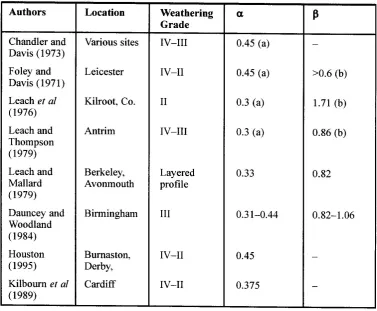
2.5 EFFECTIVE STRESS PARAMETERS FOR KEUPER MARL AT KILROOT (after Leach et al., 1976)
3.1 CONCRETE SPECIFICATION FOR CONCRETE USED IN FIELD TESTS
3.2 SUMMARY OF PILES INSTALLED DURING FIELD TESTS. Table courtesy of Tony Suckling (Stent Foundations)
4.1 LIST OF SAMPLES USED FOR ALL TESTS
4.2 SUMMARY OF MAIN OBSERVATIONS FROM THE FOUR PILES 4.3 SUMMARY OF MAIN OBSERVATIONS FROM USE OF THE AXIOCAM 4.4 SUMMARY OF MAIN OBSERVATIONS FROM THIN SECTIONS
List of Figures
2.1 PROCESS OF INSTALLATION OF A TYPICAL CONTINUOUS FLIGHT AUGER PILE (http://www.geoforum.com/info/pileinfo/images/fond6.jpg, 2008)
2.2 OUTCROPPING OF THE MERCIA MUDSTONE GROUP, INCLUDING THE MAJOR BASINS (Chandler et al., 2001)
2.3 POSITION OF THE CONTINENTS DURING THE PERMO-TRIASSIC (After Open University S236 Geology)
2.4 PROGRESSIVE STRATIGRAPHY OF THE MERCIA MUDSTONE GROUP AND THE SHERWOOD SANDSTONE GROUP, Adapted from Madler (2002)
2.5 UK STRATIGRAPHY FOR THE MERCIA MUDSTONE GROUP COMPARING THE OLD AND NEW NOMENCLATURE (After Howard et al., 2008).
2.6 STRATIGRAPHY OF THE KEUPER MARL (Warrington, 1970)
2.7 COMPOSITION OF THE CLAY FRACTION (<2mm) AND THE WHOLE ROCK CONTENT OF GYPSUM AND DOLOMITE OF THE MERCIA MUDSTONE GROUP (after Chandler et al., 2001)
2.8 THE RELATIONSHIP BETWEEN SPECIFIC VOLUME AND p’ OF AN OVERCONSOLIDATED SOIL (Atkinson, 1993)
2.9 GEOLOGICAL MAP FOR THE STUDY AREA, BLUE CIRCLE INDICATES LOCATION OF IBSTOCK BRICK PIT. Adapted from BGS Sheet XXIIIS.E. Leicestershire
2.10 GEOLOGICAL MAP FOR THE STUDY AREA. IBSTOCK BRICK PIT IS NOTED ON THE MAP. Adapted from BGS Sheet XXIIIS.E. Leicestershire
2.11 VARIATION IN LIQUID LIMIT WITH INCREASING WATER CONTENT WHEN PASSED THROUGH A MEAT MINCER (Atkinson et al., 2001)
2.12 FIELD APPARATUS USED TO CREATE A SOFT TOE IN PILES. Adapted from Leach et al. (1976)
2.13 GRAPH SHOWING THE RELATIONSHIP BETWEEN c' AND φ’ (Atkinson, 1993) 2.14 STRESS PROFILE FOR FOUR PILES (After O'Neil and Reese, 1972)
3.1 OS MAP SHOWING THE LOCATION OF IBSTOCK BRICK PIT (CIRCLED IN RED).
3.2 OS MAP SHOWING THE LOCATION OF IBSTOCK BRICK PIT
3.3 PLAN OF IBSTOCK BRICK PIT INCLUDING THE LOCATION OF FIELD TESTS 3.4 RIG USED TO INSTALL TEST PILES
3.5 AUGER USED TO INSTALL TEST PILES
3.6 SCHEMATIC DIAGRAM OF THE ORDER OF PILES AND EXCAVATION GEOMETRIES
3.7 SCHEMATIC DIAGRAM OF THE POSITION OF THE PILE AND SOIL IN THE BOX FROM ABOVE
3.8 FOUR PILES AND THE SURROUNDING SOIL, WITH 2 PILES COVERED IN STRETCHWRAP AND READY TO BE CUT USING THE DIAMOND SAW 3.9 TESTING APPARATUS USED FOR THE AXIOCAM
3.13 TYPICAL XRD TRACE
3.14 STANDARD SET OF SIEVES USED FOR PSD TESTS
3.15 CONE PENETROMETER EQUIPMENT USED IN LIQUID LIMIT EXPERIMENTS 3.16 EQUIPMENT USED FOR TRIAXIAL EXPERIMENTS
4.1 STRATIGRAPHY OF IBSTOCK BRICK PIT, LOGGED IN THE SOUTH WALL OF THE EXCAVATION PIT
4.2 RISINGS DURING AUGERING OF PILE MR1
4.3 SPOIL HEAP FOR PILE MR1 AS THE AUGER WAS REMOVED 4.4 SPOIL HEAP PRODUCED BY THE INSTALLATION OF PILE MR2 4.5 SPOIL HEAP PRODUCED DURING INSTALLATION OF PILE MR3
4.6 RELATIONSHIP BETWEEN THE AUGER AND THE WET SOIL AROUND PILE MR3.
4.7 REMOVAL OF THE AUGER FROM PILE MR3
4.8 SPOIL HEAP PRODUCED BY THE INSTALLATION OF PILE MR4 4.9 SECTION FROM PILE MR1 0-495mm BELOW GROUND LEVEL 4.10 SECTION FROM PILE MR1 495-819mm BELOW GROUND LEVEL 4.11 SECTION FROM PILE MR1 819-1277mm BELOW GROUND LEVEL 4.12 SECTION FROM PILE MR1 1277-1981mm BELOW GROUND LEVEL 4.13 SKETCH DRAWING AND PHOTOGRAPH OF REMOULDED MATERIAL
AROUND PILE MR1, 0-495mm BELOW GROUND LEVEL
4.14 CONTACT BETWEEN THE REMOULDED AND UNDISTURBED MATERIAL AROUND PILE MR1, 0-495mm BELOW GROUND LEVEL
4.15 AGGREGATES FROM CONCRETE OF THE PILE COMING OUT FROM THE SURFACE OF THE PILE SHAFT. PILE MR1, 0-495mm BELOW GROUND LEVEL 4.16 BOUNDARY BETWEEN THE HOST SOIL AND REMOULDED SOIL AROUND
PILE MR1, 819-1277mm BELOW GROUND LEVEL
4.17 FIRST SECTION TAKEN FROM PILE MR2 0-1000mm BELOW GROUND LEVEL 4.18 SECOND SECTION TAKEN FROM PILE MR2 1000-1457mm BELOW GROUND
LEVEL
4.19 THIRD SECTION REMOVED FROM PILE MR2 1457-1979mm BELOW GROUND LEVEL
4.20 REMOULDED ZONE OF PILE MR2 AT 0-1000mm BELOW GROUND LEVEL 4.21 REMOULDED ZONE FROM AROUND PILE MR2 AT 1000-1457mm BELOW
GROUND LEVEL
4.22 VERTICAL SECTION THROUGH THE REMOULDED ZONE OF PILE MR2 1000-1457mm BELOW GROUND LEVEL
4.23 VERTICAL SECTION WITH GREEN MOTTLING WITHIN THE REMOULDED ZONE AROUND PILE MR2, AT A DEPTH OF 1547mm BELOW GROUND LEVEL 4.24 VERTICAL ELEVATION OF THE REMOULDED SURFACE OF PILE MR2
SHOWING FREE AGGREGATES WITHIN THE REMOULDED LAYERS. 1000-1457mm BELOW GROUND LEVEL
4.25 COLOUR CHANGE BETWEEN REMOULDED AND UNDISTURBED MATERIAL FROM AROUND PILE MR2 AT A DEPTH OF 1457-1979mm BELOW GROUND LEVEL
4.27 SECOND SECTION FROM PILE MR3 510-860mm BELOW GROUND LEVEL 4.28 THIRD SECTION FROM PILE MR3 860-1210mm BELOW GROUND LEVEL 4.29 FOURTH SECTION FROM PILE MR3 1210-1831mm BELOW GROUND LEVEL 4.30 INNER EDGE OF THE SOIL-PILE INTERFACE IN THE REMOULDED SOIL
SURROUNDING PILE MR3, BASE OF SAMPLE IS FROM 860mm BELOW GROUND LEVEL
4.31 BOUNDARY BETWEEN REMOULDED AND UNDISTURBED MATERIAL FROM THE SOIL SURROUNDING PILE MR3 510-860mm BELOW GROUND LEVEL 4.32 ZONING WITHIN THE REMOULDED ZONE OF PILE MR3 510-860mm BELOW
GROUND LEVEL
4.33 ZONING OF REMOULDING WITH THE SOIL SURROUNDING PILE MR3 860-1210mm BELOW GROUND LEVEL
4.34 INNER SURFACE OF THE REMOULDED ZONE FROM AROUND PILE MR3, 860-1210mm BELOW GROUND LEVEL
4.35 ZONING WITHIN THE REMOULDED ZONE OF PILE MR3 AT 860-1210mm BELOW GROUND LEVEL
4.36 REMOULDED AND UNDISTURBED MATERIAL FROM PILE MR3 860-1210mm BELOW GROUND LEVEL
4.37 REMOULDED ZONE FROM AROUND PILE MR3 860-1210mm BELOW GROUND LEVEL
4.38 FIRST SECTION TAKEN FROM PILE MR4 0-451mm BELOW GROUND LEVEL 4.39 THIRD SECTION TAKEN FROM PILE MR4 951-1342mm BELOW GROUND
LEVEL
4.40 FINAL SECTION TAKEN FROM PILE MR4 1342-1962mm BELOW GROUND LEVEL
4.41 SOIL-PILE INTERFACE OF PILE MR4 AT A DEPTH OF 451-951mm BELOW GROUND LEVEL
4.42 TWO LAYERS OF REMOULDED MATERIAL AND THEIR BOUNDARY WITH UNDISTURBED HOST SOIL. SAMPLES TAKEN FROM 1342mm BELOW GROUND LEVEL
4.43 REMOULDED MATERIAL FROM 1600mm BELOW GROUND LEVEL SHOWING THE DISTINCT COLOUR AND TEXTURE DIFFERENCES BETWEEN THE REMOULDED AND HOST SOILS
4.44 ENLARGED PHOTOGRAPH OF THE REMOULDED ZONE OF PILE MR1, 1177-1277mm BELOW GROUND LEVEL
4.45 REMOULDED ZONE OF PILE MR1, 1177-1277mm BELOW GROUND LEVEL 4.46 FISSURING WITHIN THE REMOULDED ZONE OF PILE MR1 581mm BELOW
GROUND LEVEL
4.47 SAMPLE TAKEN FROM THE REMOULDED ZONE SURROUNDING MR2 690-1000mm BELOW GROUND LEVEL
4.48 ENLARGED SECTION FROM FIGURE 4.47, THE REMOULDED ZONE SURROUNDING MR2 690-1000mm BELOW GROUND LEVEL
4.49 SECTION FROM AROUND PILE MR2 TAKEN FROM BELOW 1337mm BELOW GROUND LEVEL
4.50 REMOULDED ZONE FROM AROUND PILE MR3 0-510mm BELOW GROUND LEVEL
4.52 REMOULDED ZONE FROM PILE MR4, 0-451mm BELOW GROUND LEVEL. 4.53 REMOULDED ZONE FROM AROUND PILE MR4, 922mm BELOW GROUND
LEVEL
4.54 REMOULDED ZONE SURROUNDING PILE MR4 AT 922mm BELOW GROUND LEVEL
4.55 VERTICALLY TAKEN THIN SECTIONS THROUGH THE REMOULDED ZONES AROUND ALL FOUR PILES
4.56 HORIZONTALLY TAKEN SLIDES FROM AROUND ALL FOUR PILES 4.57 THIN SECTIONS VIEWED UNDER THE LIGHT REFLECTED MICROSCOPE 4.58 SCANNING ELECTRON MICROSCOPE PHOTOGRAPH FROM UNDISTURBED
MATERIAL SURROUNDING PILE MR1, 1177-1277mm BELOW GROUND LEVEL AND 50mm FROM THE PILE
4.59 SAMPLE TAKEN FROM THE REMOULDED ZONE SURROUNDING PILE MR1, 1177-1277mm BELOW GROUND LEVEL, 0mm FROM THE PILE
4.60 SAMPLE TAKEN FROM THE UNDISTURBED MATERIAL SURROUNDING PILE MR2 1337mm BELOW GROUND LEVEL, 50mm FROM THE PILE
4.61 ENLARGED VIEW OF THE UNDISTURBED SAMPLES TAKEN FROM AROUND PILE MR2 1337mm BELOW GROUND LEVEL, 50mm FROM THE PILE
4.62 PHOTOGRAPH TAKEN USING THE SEM OF REMOULDED MATERIAL FROM THE ZONE SURROUNDING PILE MR2 1337mm BELOW GROUND LEVEL, 0mm FROM THE PILE
4.63 SEM PHOTOGRAPH TAKEN FROM THE FIRST REMOULDED ZONE OF PILE MR3, 860-960mm BELOW GROUND LEVEL, 0-2mm FROM THE PILE
4.64 FIRST REMOULDED LAYER TAKEN FROM AROUND PILE MR3, 860-960mm BELOW GROUND LEVEL, 0-2mm FROM THE PILE
4.65 SAMPLE TAKEN FROM THE SECOND REMOULDED ZONE SURROUNDING PILE MR3, 860-960mm BELOW GROUND LEVEL, 2-22mm FROM THE PILE 4.66 SECOND LAYER OF REMOULDING FROM AROUND PILE MR3, 860-960mm
BELOW GROUND LEVEL, 2-22mm FROM THE PILE
4.67 SECOND REMOULDED LAYER FROM AROUND PILE MR3, 860-960mm BELOW GROUND LEVEL, 2-22mm FROM THE PILE
4.68 THIRD REMOULDED LAYER SURROUNDING PILE MR3, 860-960mm BELOW GROUND LEVEL, 22-70mm FROM THE PILE
4.69 SOIL FROM THE REMOULDED ZONE SURROUNDING PILE MR4, 922mm BELOW GROUND LEVEL, 0mm FROM THE PILE
4.70 WATER CONTENT VARIATION WITH DEPTH DOWN THE PILE FOR ALL PILES
4.71 WATER CONTENT VARIATION WITH HORIZONTAL DISTANCE FROM THE PILE FOR ALL PILES
4.72 CHEMICAL ANALYSIS OF SOIL OUTSIDE THE REMOULDED ZONE - ALL PILES
4.73 CHEMICAL ANALYSIS OF SOIL WITHIN THE REMOULDED ZONE - ALL PILES
4.74 CHEMICAL ANALYSIS OF SAMPLES SCRAPED FROM THE PILE SHAFT - ALL PILES
4.76 CHEMICAL ANALYSIS OF SOIL WITHIN THE REMOULDED ZONE EXCLUDING SiO2 - ALL PILES
4.77 CHEMICAL ANALYSIS OF SAMPLES SCRAPED FROM THE PILE SHAFT EXCLUDING SiO2 - ALL PILES
4.78 CHEMICAL ANALYSIS OF SOIL SURROUNDING PILE MR1 4.79 CHEMICAL ANALYSIS OF SOIL SURROUNDING PILE MR2 4.80 CHEMICAL ANALYSIS OF SOIL SURROUNDING PILE MR3 4.81 CHEMICAL ANALYSIS OF SOIL SURROUNDING PILE MR4 4.82 ABUNDANCES OF MINERALS WITHIN THE CLAY FRACTION OF
UNDISTURBED SOIL
4.83 ABUNDANCES OF MINERALS WITHIN THE CLAY FRACTION OF REMOULDED SOIL
4.84 ABUNDANCES OF MINERALS WITHIN THE WHOLE ROCK, UNDISTURBED SOIL
4.85 ABUNDANCES OF MINERALS WITHIN THE WHOLE ROCK, REMOULDED SOIL
4.86 PSD CURVE FOR THE SAMPLES TAKEN FROM AROUND PILE MR1 4.87 PSD CURVE FOR THE SAMPLES TAKEN FROM AROUND PILE MR2 4.88 PSD CURVE FOR SAMPLES TAKEN FROM AROUND PILE MR3 4.89 PSD CURVE FOR SAMPLES TAKEN FROM AROUND PILE MR4
4.90 PLASTIC AND LIQUID LIMITS OF SOIL TAKEN FROM AROUND ALL FOUR PILES
4.91 MEAN EFFECTIVE STRESS PLOTTED AGAINST THE DEVIATOR STRESS FOR ALL TRIAXIAL TESTS
4.92 AXIAL STRAIN PLOTTED AGAINST q’/p’
4.93 AXIAL STRAIN PLOTTED AGAINST DEVIATOR STRESS FOR ALL TRIAXIAL TESTS
4.94 THE EFFECT OF WATER CONTENT UPON SHEAR STRESS IN AN UNDRAINED SOIL (after Stallebrass, 2009)
City, University of London Northampton Square London EC1V 0HB United Kingdom
T +44 (0)20 7040 5060
THE FOLLOWING PARTS OF THIS THESIS HAVE BEEN REDACTED
FOR COPYRIGHT REASONS:
Figure 2.1: PROCESS OF INSTALLATION OF A TYPICAL CONTINUOUS FLIGHT AUGER pg. 193
Figure 2.9: GEOLOGICAL MAP FOR THE STUDY AREA, BLUE CIRCLE INDICATES LOCATION OF IBSTOCK BRICK PIT. Adapted from BGS Sheet XXIIIS.E. Leicestershire pg. 200
Figure 2.10: GEOLOGICAL MAP FOR THE STUDY AREA. IBSTOCK BRICK PIT IS NOTED
Acknowledgements
I would like to thank all the members of GERC for all their support during this
project. I would especially like to thank Dr Sarah Stallebrass for her constant
and unending support, encouragement and enthusiasm. Thank you to Dr Jackie
Skipper for her supervision and enthusiasm and to Dr Richard Goodey for trying
to enlighten me in the ways of bacon.
I would like to thank the many lab technicians and experts who helped me to
complete this project. Specifically, I would like to thank Keith Osborne and
Melvyn Hayes (City University), Jenny Huggett and Martin Gill for all their help
with XRD work, Sarah James for her help using the ICP, Ben Williamson and
Alex Ball for their help with the SEM, Keith Ambrose and David Entwistle
(BGS) for escorting me around my field area and sharing their huge expertise.
Thanks to Leonora Begaj-Qerimi, Julia Witton-Dauris and Alexis Rose for their
continuing friendship, kindness and enduring patience.
To Louisa Preston for always being a shoulder to cry on or a distraction at just
the right moment. To Yussanne Ma (I’m looking forward to opening that last
envelope), Rebekah Reeson, Becky Hulse, Sue Fowler, Ruth Chubb, Scott
Lawton and Bianca Ackerman for never ending encouragement.
To Paul Ratcliffe for having put up with me! Thank you for being patient and
supportive and most of all for proof reading my dissertation. I am eternally
grateful and would not be in this position without you.
To my parents and my sister for constant encouragement and for putting up with
me!
Finally to Stent Foundations for their generous funding during this project and
specifically the help and support of Viv Troughton, Tony Suckling and Andy
Declaration
I grant powers of discretion to the University Librarian to allow this dissertation
to be copied in whole or in part without further reference to me. This permission
covers only single copies made for study purposes, subject to normal conditions
Abstract
The research reported in this dissertation examines the physical and chemical changes that occur to in situ soil at the soil-pile interface for continuous flight auger piles installed in the Mercia Mudstone Group. Four Continuous Flight Auger (CFA) piles were installed in the Gunthorpe Member of the Mercia Mudstone Group, central England. The effect on the soil-pile interface of over-rotation of the auger during installation, and the addition of water during installation were investigated.
Once the piles had been left to cure, they were excavated and returned to City University, London, with the surrounding soil. The excavated piles and soil were examined using a variety of microscopic and macroscopic techniques including inductively coupled plasma spectroscopy (ICP) and X-ray diffraction (XRD); with water contents, chemical content (ICP) and mineralogical content (XRD) tested. Plastic index and particle size distribution tests were used to show the physical effects of piling on the host soil and preliminary strength testing was carried out to provide insight into the strength characteristics of the soil surrounding the pile.
In all four piles a distinct zone of remoulding was observed around the pile shaft. In each case the remoulded zone was a brown to red, clay rich layer varying between 0mm and 55mm in thickness. In almost all cases this remoulded zone had a structure and fabric which was not related to the in situ soil. Around all piles it was further noted that vertical fissures were present, and fanned out from the pile shaft in a clockwise direction.
Two of the piles were installed with the addition of water. Around these piles it was noted that the remoulded layer often split into two or three distinct layers, with one of these layers often containing millimetre scale aggregations of green silt.
Tests showed a higher percentage of clays present within this remoulded zone, and indicated that SiO2 (a major rock forming element and considered by some
authors to be an aggregating agent within the Mercia Mudstone Group) was more abundant within remoulded than undisturbed soil. The clay fraction showed a low abundance of high swelling clays in all cases.
Definition of Terms
Aggregates from concrete:
Aggregates used as part of concrete mix, seen within this study as millimetre to
centimetre scale, sub-rounded to sub-angular flints
Aggregates of clay:
Individual clay minerals cemented together with CaO or SiO2 into silt sized
particles.
Afossiliferous:
Does not contain fossils
bgl:
Below ground level
BGS:
British Geological Survey
c’:
effective cohesion
Cc:
Slope of normal compression line
Clasts:
Rock fragment formed by the breakdown of other rocks
Clay Mineral Assemblage:
A group of clay minerals commonly found together in a particular geological unit
CSL:
Critical State Line
Host soil:
Soil into which piles were installed, particularly the soil surrounding the
remoulded zone which appeared unaffected by the piling process
ICP:
Inductively Coupled Plasma, a highly powerful technique for analysing the
Laterally Discontinuous:
Does not continue along a horizontal plane, but may appear sporadically along
the same horizon
Laterally Extensive:
Continues along a horizontal plane for a large distance
MMG:
Mercia Mudstone Group
Normally Installed Pile:
Where a pile was installed as would usually be required on site, with no special
instructions such as over-rotation
p’:
Mean normal stress
PI Tests:
Plastic Index tests
Playa Lake:
A temporary shallow lake
PSD Tests:
Particle Size Distribution tests
SEM:
Scanning Electron Microscope
Slurry:
Water and clay at approximately the plastic limit, giving a sludgy material which
is hard to pile or tunnel through
Remoulded Zone:
Area surrounding the pile shaft appearing different from the host soil in colour
and texture
Soil-Pile Interface:
Where the soil and pile shaft touch
Syn-:
During
v:
Specific Volume
Vertically Discontinuous:
Does not continue along a vertical plane, but may appear sporadically with depth
XRD:
X-Ray Diffraction, a powerful tool in assessing which minerals are present in a
sample. Particularly useful for clay species where individual crystals are too
small for visual identification
τ':
Shear Stress
φ
’:Angle of friction
φ
c’:The following diagrams indicate some commonly used words of phrases within
this thesis:
Diagram showing conventions used to refer to the pile
Diagram showing terminology used to describe the soil surrounding the pile
Horizontally away from the pile
Horizontally towards the pile
Horizontally around the pile
Vertically up the pile
Vertically down the pile
Undisturbed host soil
Remoulded soil
Pile shaft Soil-pile
interface
Diagram showing the pattern of fractures commonly seen within the remoulded
zones of all four piles as seen from above
Top of pile shaft
Clockwise fanning pattern of fractures
1
Introduction
1.1
Background
In 2005 City University London was approached by Stent Foundations to
investigate the reasons why some Continuous Flight Auger (CFA) piles augered
into mudrocks, in particular the Mercia Mudstone Group, have a shaft capacity
which is significantly lower than that expected from calculations. It is commonly
understood within the industry that piling in some clay rich soils may become
problematic due to the issues of slurrying during installation and unexplained
loss of capacity of piles after installation, but sadly case histories where this has
occurred have rarely been documented in the literature.
1.2
Aims of the Project
The aims of the project are to look at the changes to the in situ soil at the soil-pile
interface caused by installation of Continuous Flight Auger (CFA) piles in the
Mercia Mudstone Group, and in particular to:
• Characterise the changes that occur in the soil at the soil-pile interface.
• Investigate the mechanisms that might create these changes.
• Characterise the effect of over-rotating the auger during installation.
• Characterise the effect of the presence of free water during installation.
• Draw preliminary conclusions about the influence of changes in the soil
at the soil-pile interface on strength properties of the soil.
• Recommend how to maximise the shaft capacity of piles augured into the
1.3
Objectives of the Project
The aims detailed above were achieved by:
• Organising a field test where Continuous Flight Auger (CFA) piles were
installed so that the soil-pile interface could be observed.
• Observing the soil-pile interface within the soil.
• Varying the pile installation method such that water was added, the auger
over-rotated, or both.
• Testing the strength and physical properties of material at the soil-pile
interface.
• Carrying out detailed logging and observations of the soil structures and
fabric of the soil-pile interface at both macro and micro scales.
1.4
Basic Methods Used in the Project
The aims and objectives of the project were met using the following methods:
• Four test piles were augered into the Gunthorpe Member of the Mercia
Mudstone Group.
• The four test piles were augered in a manner which varied the free water
during augering, and varied over-rotation of the auger.
• The piles and their surrounding soil were excavated and removed from
site.
• Each pile and the soil surrounding it were examined in the laboratory,
with particular respect to the soil-pile interface.
• Water content measurements were taken at the soil-pile interface of each
pile, and, where possible, at distances of 50 and 100mm horizontally from
the pile.
• Microstructures of both remoulded and apparently undisturbed soil were
observed using axiocam, thin section and scanning electron microscope
• Plastic index tests were performed on both remoulded and apparently
undisturbed soil.
• The effects of piling upon soil chemistry and mineralogical make up were
tested using ICP-AES and XRD analysis respectively.
• Particle size distribution tests were used to test the effect of mechanical
breakdown of soils during the piling process.
• Limited strength testing was undertaken to establish key features of the
behaviour of the remoulded soil and for a preliminary evaluation of
changes in strength properties.
1.5
Terminology
This dissertation relies on consistent description of changes in soil fabric,
structure and texture. Soil which has undergone a visible change in fabric and
structural properties during pile installation will be referred to as “remoulded”.
Other descriptive terms used in this dissertation, some of which have specific
2
Literature Review
2.1
Introduction
In this Chapter, literature is reviewed to provide a background to the project and
discuss the facts and assumptions which underpin the work undertaken. To
understand the processes affecting Continuous Flight Auger (CFA) piles both
during and after installation, it is necessary to also understand the piling process,
and the ground into which the piles are being installed. Hence issues relating to
the stratigraphy of the Mercia Mudstone Group and the theory and practice of
CFA piling are reviewed.
The initial sections in this Chapter provide background information, with later
sections discussing some of the reported problems with piling in the Mercia
Mudstone Group. Unfortunately there is very little published information, as
most cases are relatively small scale problems which have not merited extensive
investigation and consequently are not reported in the literature.
The literature describing the Mercia Mudstone Group has been complicated and
confused at times. A recent stratigraphy was published by Howard et al. (2008)
and has been adopted for this project; however, previous stratigraphies dating
back to when the Group was called the Keuper Marl have given rise to some
confusion in the literature, especially where authors are not using the current
nomenclature.
While the Group was extensively studied in the 1960s, work referring to the
engineering properties of the group which is more recent than the mid 1970s is
sparse and usually uses the old nomenclature. Published work on the Group with
specific references to CFA piling (only introduced into the UK in the 1970s) is
2.2
Continuous Flight Auger (CFA) piling
Piled foundations are a type of deep foundation commonly used to take heavy
loads, especially where soils are weak at shallow depths. Piled foundations are
designed to take loads from shallow depths – where soil often has a low
confining stress – to greater depths, where soil has a high confining stress. Piled
foundations are typically made from concrete, steel or timber.
An applied load on a pile is resisted by the bearing capacity of the soil at the base
and friction along the shaft. Piles are usually designed with high factors of safety
in order to minimise the settlement of the pile. Atkinson (1993) notes that piles
installed in clays tend to settle with time due to the dissipation of excess pore
pressures generated by undrained loading of the clay. This causes an increase in
the effective stress within the soil. Recent changes in pile design have led to the
development of an effective stress approach to piling. This method, referred to
as the β method, assumes that the transfer of load from a pile to the soil is mainly
controlled by the effective stress in the soil and that the resistance at the toe and
friction in the shaft are proportional to the effective overburden stress (Fellinius,
1998).
Driven piles (installed by driving concrete or steel into the ground and,
optionally, later filling with reinforced concrete) and bored piles (installed by
producing a void into which concrete is set) are both commonly used within the
construction industry.
Continuous Flight Auger (CFA) piles are installed using a corkscrew-like auger
to displace soil in the ground. Concrete is poured into the resulting hole through
the hollow auger stem during removal of the auger. This means that, unlike other
bored pile methods, when CFA piling is used there is no point where a gap is left
in the soil which is not filled with either the auger or concrete. A schematic
CFA piling is a rapidly increasingly used technique, with reports that bored and
CFA piles make up 50% of the world pile market (Van Impe, 2003). CFA piling
was first used in the USA in the 1950s and in Europe in the 1970s (Albuquerque
et al., 2005). Fleming (1992) cites the major advantages of the CFA technique as
being environmental, with little noise and little vibration during the installation
of piles. The use of this technique also means that where the water content of the
host soil is high, or water bearing layers are present, there is no need to support
the hole during construction with either bentonite slurry or a casing.
The auger used for CFA piling has a width dependant upon the dimensions
required for the pile which are in turn dependant on load calculations, and the
auger is always screwed into the soil clockwise (Heathcote, 2007).
Due to the mode of installation, various problems may occur during CFA piling.
Fleming et al. (1992) discussed some common problems encountered during
CFA piling, and concluded that the most common problems are due to
excessively rapid removal of the auger, causing soil to be carried backwards into
the pile shaft, meaning that the upper portions of the pile shaft may become
contaminated with soil. Other potential problems with CFA piles listed by
Fleming et al. are all due to over-rotation of the auger (when the auger is allowed
to continue to spin without further gain of depth, either at the toe of the pile or at
a shallower depth). In particular, when the auger meets hard beds below water
bearing beds this can cause the auger to over-rotate, loosening soil adjacent to the
pile and allowing water filled cavities to develop. Excessively rapid removal of
the auger affects the integrity of the pile; over-rotation of the auger affects the
soil-pile interface. Both issues affect the pile load displacement behaviour but
for different reasons.
Hird et al. (2008) studied the effects of CFA piling on the soil surrounding the
piles. They used a transparent, artificial soil, so the effects of piling could be
observed within the ground. Tests varied the vertical speed used to install piles,
and the number of rotations of the auger used to get to the toe during installation.
It was found that when the auger was normally rotated (i.e. installed with the
into the soil by the height of one flight), ground displacements were negligible.
When the auger was over-rotated either ground displacements were small and a
self supporting hole was formed, or the soil was pulled onto the auger. The study
did not discuss why the two differing reactions to over-rotation occur, or the
effects this has upon shaft capacity. It is interesting to note the potential for soil
to fall into the auger and, presumably, being subsequently removed by the auger.
This may account for some widening of piles noted later in this Chapter (see
section 2.10).
The factors affecting shaft adhesion in piled foundations were studied by
Anderson et al. (1985) who installed piles in the laboratory into beds of kaolin,
with voids left at the base of the piles. The piles were left to cure for 7 days and
then loaded. It was found that maximum adhesion between the pile shaft and
adjacent soil was achieved at settlements of 1% of the pile diameter. It was
concluded that such small settlements indicate that soil is presheared during
augering, and small movements during settlement are sufficient to activate the
residual strength created within the clay by this preshearing.
Anderson et al. (1985) also concluded that the horizontal effective stresses within
the soil before augering are recovered with time, but that the time required to
recover these stresses is dependent on the time taken between augering and
filling with concrete. If this time increases then so does the time required for
recovery of the horizontal in situ stresses. If this is assumed to be correct, it is
consistent with the idea that over-rotated augers which become blocked, and
therefore take longer to fill with concrete, may have a poor shaft capacity due to
horizontal stresses reducing during the augering process, since the auger cannot
provide perfect support to the soil.
2.3
Influence of Host Soil on Shaft Capacity
There are many reasons for over predictions of shaft capacity of piles. Poor
foundations may all be culprits. Mandolini et al. (2005) discussed the effects of
the installation technique upon bearing capacity and load-settlement behaviour,
and state that the dominant factor in the behaviour of piles is the characteristics
of the host soil directly adjacent to the pile, as this controls the degree of
cohesion between the soil and pile. They also conclude that the installation of
piles directly affects the stress states within the soil, and therefore that the
original soil present and the stress states within it are of great importance. Whilst
knowledge of the stress history of the host soil is important when designing piled
foundations, it is also important to consider the geological history and mode of
deposition of a soil as in many cases the mode of deposition of a soil may control
its behaviour more than its stress history. Particle size distribution, percentage of
clay particles and mineralogy should all be considered important factors during
pile design, as discussed later within this Chapter.
2.4
Introduction to the Mercia Mudstone Group
The Mercia Mudstone Group (previously known as the Keuper Marl) is a
Triassic age (Arthurton, 1980) deposit covering much of central England, up to
the north of England, under Cheshire and down as far as Devon (Figure 2.2).
The Mercia Mudstone Group is important in engineering terms as it sits under
many major cities within the UK, such as Birmingham, Coventry, Bristol and
Cardiff. The deposit is often over a kilometre thick.
During the Carboniferous, plate tectonics caused collisions between the
continents, leading to the formation of a supercontinent called Pangaea (OUP,
1983, see Figure 2.3). When the Mercia Mudstone Group was laid down, in the
Triassic, England was on the inside of the supercontinent Pangaea, to the north of
the Variscan mountain belt (Howard et al. 2008). At this time, Pangaea had
begun to break apart, leading to the formation of many fault bounded extensional
basins in southern, central and north-west England (Warrington and
During the early Triassic, a monsoonal climate meant that the Variscan mountain
belt contained a large river system flowing northwards across what is now
southern Britain (Howard et al. 2008). This caused thick deposits of pebbly
sands to be lain down, forming what is now considered to be the lower part of the
Sherwood Sandstone Group (Howard et al. 2008). Upper parts of the Sherwood
Sandstone Group contain aeolian and fluvial sandstones and show onlapping (see
glossary) of the sediments onto the Variscan mountain belt.
These depositional sequences are mirrored in the stratigraphy, giving a sandstone
sequence, ranging from pebbly to conglomeritic, deposited in a braided stream
system flowing northwards. This facies is called the Sherwood Sandstone
Group.
Above the Sherwood Sandstone Group lies the base of the Mercia Mudstone
Group. Basal beds of the Mercia Mudstone Group indicate a southerly retreat of
river systems in the Variscan mountain belt and an onset of “subaqueous
hypersaline and evaporitic mudflat environments” (Howard, 2008; Warrington
and Ivimey-cook, 1992) meaning a flood plain which repeatedly flooded with
saline water and dried out leaving salt rich deposits. According to Arthurton
(1980); Warrington and Ivimey-cook (1992) and Talbot et al. (1994), four main
modes of deposition are seen within the Mercia Mudstone Group; brackish or
saline lakes allowing mud and silt to settle out of water; flash flood resulting in
rapid deposition of silt and fine sand; wind blown dust settling on wet mudflats
and chemical precipitation of evaporating salts, mainly halite and gypsum.
Figure 2.4 shows a schematic diagram of the progression of deposits within the
Mercia Mudstone Group and Sherwood Sandstone Group.
In contrast with the Sherwood Sandstone Group below, the sequence of deposits
in the Mercia Mudstone Group indicate the climate of the UK becoming drier. As
the depositional environment of the Sherwood Sandstone Group switched to the
depositional environment of the Mercia Mudstone Group, a complex basin
sequence of sabkhas, saline mudflats and temporary lakes developed which
2.5
Mineralogy and Stratigraphy of the Mercia Mudstone
Group
2.5.1
Introduction
The stratigraphy of the Mercia Mudstone Group has been examined by a number
of authors, for example, Howard (2008) and Warrington (1970). It would be usual in a group as large as the Mercia Mudstone Group for fossils to hold the key to matching up sequences (De Freitas et al. 2007; Zalasiewicz et al. 1988), but due to the largely afossiliferous nature of the group (Howard et al., 2008) other methods must be used. Warrington et al. (1980) proposed that the stratigraphy might be defined using the pollen spores or mineralogy. The high clay content of the Mercia Mudstone Group adds further complications to its
engineering properties, due to slurrying (see glossary) of the soil during augering
and expansion and shrinkage of the soil with the addition of water or mixing
during engineering processes. Hence where mineralogy may be an important key
for the stratigraphy of the group, it is also useful to look at this from an
engineering point of view.
The stratigraphy of the Mercia Mudstone Group was split into 5
lithostratigraphical units (A-E) by the British Geological Survey (BGS) (Howard
et al., 2008). A summary of these units is given below, with specific reference to
Unit B (the unit containing all members found at the test site used for field tests
reported in this dissertation, Ibstock Brick Pit). Figure 2.5 shows a stratigraphy
for the Mercia Mudstone Group of the East Midlands shelf, encompassing the
Gunthorpe Member - the member used for the field tests described in this
dissertation (Ambrose, 2006). Because the Gunthorpe Member was the member
used for field tests, it is this level of the stratigraphy which will be mostly
2.5.2
Unit A
This unit is the lowest unit stratigraphically and is comprised of brown mudstone
and siltstone interbedded with a variable but approximately equal proportion of
pale grey-brown sandstone. Beds are planar, with sandstone beds generally
being less than 5mm in thickness and sandstones generally being fine to very fine
grained, although occasionally medium grained with a high mica content
(Howard et al., 2008).
Gypsum and anhydrite are present within Unit A, but less abundant than in
higher units and where present are seen as veins and nodules. Unusually for the
Mercia Mudstone Group fossils are also present in the form of miospores, with
vertebrate tracks and the brachiopod Lingulida also found in some regions
(Howard et al. 2008).
Unit A is the hardest of the five units to constrain stratigraphically as it is not
differentiated in all regions, has a diffuse top and base and is interbedded with
the top of the Sherwood Sandstone and the bottom of Unit B (Howard et al.,
2008).
Unit A has been given different Formation names, according to which basin it is
found within and is known variously as the Tarporley Siltstone Formation, Maer
Formation, Denstone Formation and Sneinton Formation.
The base of Unit A (or the Mercia Mudstone Group where Unit A is not
observed) becomes progressively younger southwards due to the southerly
advancement of the basement through time. (Howard et al. 2008)
2.5.3
Unit B
This is the unit containing all the members found within the Ibstock Brick Pit
(Gradstein et al., 2004) in age. The unit contains mainly red, and less
commonly, green and grey dolomitic mudstones and siltstones, ranging from
finely laminated to structureless. Thin beds of coarse siltstone and very fine
sandstone are found throughout the unit, with individual beds typically 2-6mm in
thickness, green-grey in colour with a strong dolomitic cement (Howard et al.,
2008). Dolomite is a carbonate mineral frequently found in sedimentary rocks.
Unit B may be structureless in some regions due to loss of original fabric caused
by frequent wetting and drying syn- and post- deposition causing constant
growth and dissolution of salts.
Thick deposits of halite (salts) are found within Unit B, in the middle and lower
sections. Geophysical log markers (typically thick beds) can be used to correlate
strata within the basins, but not between basins due to the local presence of these
deposits which may disturb distinctive patterns within the logs (Howard et al.,
2008).
The unit is usually 150-300m thick, but has large variations between basins. In
the East Midlands shelf the unit contains the Radcliffe, Gunthorpe and Edwarlton
Members, which were downgraded from Formations to Members by Howard et
al. (2008). These are collectively referred to under the umbrella of the Sidmouth
Mudstone Formation, with some inclusions of the Cotsgrave Sandstone Member.
The type section of the Sidmouth Mudstone Formation is the South Devon coast
between Sidmouth [Grid reference: SY 129 873] and Weston Mouth [Grid
reference: SY 163 879].
In the East Midlands shelf the Members of the unit are distinguished only by
using “fairly subtle lithological characteristics and partly by using skerry beds as
mappable markers” (Chandler, 2001).
The Gunthorpe Member of the Mercia Mudstone Group is predominantly dark
red, red-purple or red-brown horizontally laminated mudstones with interlayers
of greenish grey mudstones appearing in many areas. This sequence of
are massive or blocky, horizontally cross bedded or rippled. Dolomitic
sandstones may also be present and make up hard beds, with some secondary
veins of gypsum present (Mader, 2002). The member is a deposit from a series
of playa lakes present in the UK during the Triassic, and represents a period
where stagnant water bodies in a desert environment characterised the
environment, with little in the way of disturbances or flood events. Moving
bodies of water were isolated, small and sparse.
2.5.4
Unit C
This unit is differs greatly from other units in the Group, with a contrasting
colour and unique lithologies and mineralogy. It is heterolithic and consists of
grey and green mudstone interbedded with paler grey-green to buff coloured
siltstone and fine to medium grained multi-coloured sandstone with localised
pebbly horizons. Invertebrate and vertebrate macrofossils are found, in some
areas very abundantly (Howard et al., 2008).
The mineral assemblage is rich in mixed layer clays (meaning that clays are of
mixed type with one type of clay fitting into the molecular structure of another
type of clay), making it distinct from the units above and below (Jeans, 1978).
The thickness of Unit C is typically only 10m with local variations and is known,
amongst other names, as the Arden Sandstone, Butcombe Sandstone Member
and, in the East Midlands shelf, Hollygate or Dane Hills Sandstone Members.
2.5.5
Unit D
This unit is superficially similar to Unit B but with structureless red-brown
dolomitic mudstones dominating. Halite is present only at the base of the unit,
and gypsum and anhydrite are abundant (Howard et al. 2008).
2.5.6
Unit E
This unit is the uppermost unit of the Mercia Mudstone Group and is a laterally
unevenly spread layer of structureless, greenish grey dolomitic mudstones and
siltstones with thickness varying from under 10m up to 67m thick.
This unit is known as the Blue Anchor Formation in all basins and was formerly
known as the Tea Green Marl.
2.5.7
Historical Stratigraphy of the Mercia Mudstone Group
The Mercia Mudstone Group has a long and complicated history of
stratigraphical classification and was previously called the Keuper Marl.
Warrington (1970) discussed the stratigraphy of the Keuper Marl and a summary
is given in this section. Figure 2.6 shows a stratigraphy of the Keuper Marl,
including the stratigraphy for the East Midlands shelf. It can be seen that
although some of the names and classifications have been changed since this
stratigraphy was published (for example, the Harlequin Formation is no longer
within the formal stratigraphy), much of the understanding of the group has not
changed since the 1960s. The stratigraphy is not split into units as by Howard et
al. (2008), but it may be presumed from the stratigraphy presented that the
present Gunthorpe Member would fall roughly within the Harlequin and Carton
Formations presented by Warrington (1970).
The Sherwood Sandstone Group underlying the Mercia Mudstone Group was
previously defined as the Bunter Sandstones, with a large discontinuity lying
between these sandstones and the mudstones of the Mercia Mudstone Group
above.
Warrington (1970) describes the mudstones of the Mercia Mudstone Group as
being a deposit from a hypersaline, quiet environment where deposition of very
to characterise the UK during this time, in line with the later interpretations of
the group by e.g. Howard et al. (2008).
2.5.8
Brief Description of Clay Mineralogy
According to Eberl (1984) clay minerals are produced in three main ways:
inheritance (minerals are bought in from another area by sedimentary processes);
neoformation (minerals have precipitated from solution or formed from reactions
with amorphous material); and transformation (an inherited clay which has
reacted via ion exchange or layer transformation to change species). These
processes are controlled by the environment and available energy during and
after deposition. The Mercia Mudstone Group contains clays produced by all
three methods.
Clay minerals are formed of two fundamental units, silicon tetrahedra and
magnesium or aluminium octahedra. The number and arrangement of these units
and the manner in which they are held together defines which clay mineral is
produced. Clay minerals may be split into three broad types: high swelling,
medium swelling and low swelling. When minerals from the smectite group
come in to contact with water they are known to expand rapidly in volume, by a
greater amount than the kaolinites, thus making them a high swelling clay
mineral (Mitchell, 1993). All three types of clays are known to be found within
the Mercia Mudstone Group in varying amounts dependant upon location and
stratigraphic formation.
2.5.9
Mineralogy of the Mercia Mudstone Group
The mineralogy of the Mercia Mudstone Group is useful to understand when
dealing with the group, as it has a number of diagnostic uses. It is generally
accepted that the plasticity and mechanical properties of a soil are influenced by
the type, size and abundance of clay minerals present (Dumbleton and West,
susceptibility to weathering. Consequently, the predicted engineering behaviour
of a soil is highly dependant upon the minerals present and their textures
(presence of fractures, fissures and fabrics).
According to Hobbs et al. (2002) the main non clay minerals within the Mercia
Mudstone Group are quartz, calcium carbonate, magnesium carbonate, calcium
sulphates, micas, iron oxides and halite, with a possible presence of feldspar and
other heavy minerals. Abundant clay minerals are illite, chlorite, mixed layer
illite-smectite or chlorite-smectite and, less abundantly, smectite.
Figure 2.7 shows a generalised clay mineral composition for the Gunthorpe
Member and other members commonly found in the Midlands (adapted from
Bloodworth and Prior, 1993). The Figure shows highly variable abundances of
illite (approximately 38-82% of the total clay fraction), with no vertical
sequences of abundances. Moreover there is a highly variable distribution across
the thickness of the Gunthorpe Member.
The abundance of chlorite is low across the Gunthorpe Member, with little
vertical variation, and never exceeds 20% of the total clay fraction.
Chlorite-smectite abundances are highly variable, with their percentage of the clay
fraction varying between a few percent to 60% along one lateral horizon. It
should be noted that along the same lateral horizon there was also a large
variation in the percentage of illite, but the value for chlorite was only slightly
affected.
The percentage of smectite interlayers (common in weathering horizons) in
multilayered chlorite/smectite is fairly constant at around 55% for the whole of
the Mercia Mudstone Group, except at the top of the group (Unit E) where the
percentage rapidly decreases to zero.
Jeans (1976) published a comprehensive study of the mineralogy of the Mercia
Mudstone Group and proposed two clay mineral assemblages (see glossary). Of
these two assemblages, the first was found in all samples and contained
variations. The second clay assemblage identified by Jeans (1976) showed a
sparse distribution of sepiolite, palygorskite, smectite, smectite/mica,
smectite/chlorite, corrensite and chlorite with each mineral appearing in well
defined regions, correlated with certain cyclic climatic events.
The assemblages identified by Jeans (1976) have not been commonly adopted by
some authors, with Howard et al. (2008) not acknowledging them within their
work. In contrast, Chandler et al. (2001) do make reference to these
assemblages, indicating that the authors consider them to be accurate.
2.6
History of the Mercia Mudstone Group
As discussed in section 2.4, the Mercia Mudstone Group was deposited in the
Triassic, 250 to 205 million years ago (Forster and Warrington, 1985). During
this time, England and much of Europe was far closer to the equator than it is
now, the Earth had a hotter climate than at present (Kidder and Worsley, 2004)
and what is now the UK and central parts of Europe was covered by a large
estuarine system within a desert.
The Quaternary (the current era) is a highly debated period of time, with even the
base of this time not being agreed by geologists. It began either at 2.6Ma before
present (Bowen and Gibbard, 2007; Pillans and Naish, 2004) or 1.8Ma before
present (Hilgen, 1991). During this era much of England was subjected to
repeated loading and unloading events, as glaciers advanced and retreated. The
furthest south any of these ice sheets reached was approximately at the current
location of the M4 motorway. Due to the complex stratigraphy of the Quaternary
it is not yet known exactly how many glacial events occurred during this period
of time (and therefore how many loading/unloading events affected Ibstock Brick
Pit, the field area used for work for this dissertation), but it is known that the area
was affected a number of times (Bowen et al., 1986), and therefore will be
overconsolidated. Overconsolidation of a soil gives rise to undrained strength
found near the surface (Atkinson, 1993). Figure 2.8 shows the stiffness
properties for an overconsolidated soil. When a soil becomes overconsolidated,
it is because it has had an excess load applied to it, usually due to deposition of
soils on top of it, or due to glaciation. The application of this load causes the
specific volume of the soil to decrease, however, when the load is removed the
specific volume only increases very slightly so and overconsolidated soil behaves
differently to a normally consolidated soil.
However, the soil may also have been exposed at the surface and weathered by
glacial processes, as discussed by Hutchinson, J. (2001). A weathering scheme
for the Mercia Mudstone Group, with grades from I (unweathered) to IVb (fully
weathered, matrix only) was suggested by Chandler (1969) and is shown in
Table 2.1 and the resulting effect on the shear strength properties given in Table
2.2.
2.7
Local Stratigraphy of the Mercia Mudstone Group in
Ibstock
Field work for this dissertation was carried out at Ibstock Brick Pit,
Leicestershire. Figures 2.9 and 2.10 are adapted from the British Geological
Survey (BGS) map, Leicestershire XXIII, S.E. and give the geological setting of
Ibstock Brick Pit. The Figure shows that the brick pit is situated on red
mudstone with thin bands of sandstone. To the north and south of the site the
mudstone is capped with boulder clay. To the east there are outcrops of skerry
sandstone, and faulting is noted.
A visit to the pit in summer 2006 with Keith Ambrose and David Entwistle of the
BGS was of assistance in gaining an understanding of the local stratigraphy.
Ibstock Brick Pit contains three of the members of the Mercia Mudstone Group
(all within Unit B): the Tarporley, Radcliffe and Gunthorpe Members. The
Gunthorpe Member sits at the top of the Brick Pit, in the area used for this study
According to the formalised stratigraphy of Howard et al. (2008), Unit B of the
Mercia Mudstone Group should contain red, and sometimes green and grey
dolomitic mudstones and siltstones ranging from finely laminated to
structureless, with thin beds of coarse siltstone and very fine sandstone. The
localised stratigraphy observed at Ibstock Brick Pit is given in section 4.2.1 and
can be seen to fit with the formalised stratigraphy for the area.
2.8
Engineering Properties of the Mercia Mudstone Group
2.8.1
Introduction
Within this section the common engineering properties of the Mercia Mudstone
Group are discussed, along with some discussion of laboratory tests undertaken
on soil samples taken from the group, providing a background to the tests
performed during this study.
CIRIA published a report in 2001 on the engineering properties of the Mercia
Mudstone Group (Chandler et al., 2001), giving a comprehensive summary of
the research to that date, which provided much of the information reviewed in
this section.
2.8.2
Index Properties
The dominant lithology within the Mercia Mudstone Group is a red brown silty
mudstone, particularly within Units B and D as described by Howard et al.
(2008). Work by Davis (1967) and others suggests that this mudstone has an
aggregated structure. This means that while the mudstone has typically 70% clay
minerals, these are strongly bonded together so that a particle size distribution
(PSD) test gives a proportion of clay sized particles far smaller than the actual
Davies (1967) discussed aggregation ratios within the Mercia Mudstone Group,
and defined the aggregation ratio as the percentage of clay minerals present
divided by the percentage of clay sized particles. It was discovered that in the
samples Davies used, the percentage of clay minerals was between 60% and
100%, whereas the percentage of clay sized particles was between 10% and 60%,
giving an aggregation ratio between 1.4 and 10. Davies concluded that clays had
aggregated into silt sized particles, possibly due to calcite or dolomite cementing.
When the percentage of clay sized particles increases (i.e. the aggregation ratio
decreases), the plastic index does not greatly increase, typically rising from 12%
at a clay fraction of 15% to 17% at a clay fraction of 50% (Chandler et al., 2001).
This suggests that aggregated clays do not have a greater affinity for water and
therefore do not split into their constituent clays when in the presence of water
alone and so the surface area of the clay does not increase greatly under these
circumstances. It can therefore be concluded that the plastic index is not
necessarily a good indicator of those properties of the clay which are dependant
on particle size.
This theory is to some extent backed up by Atkinson et al. (2001). For this
study, plastic index tests were performed on samples from the Edwarlton
Member. The aim was to investigate the reasons why a tunnel boring machine
had become stuck after tunnelling in this member, in a tunnel known as the
Abbey Sewer tunnel. The Abbey Sewer tunnel has twice caused problems
reported within the literature. The first of these reports was from Myers and
Sindle (1994) who noted that groundwater leaking into the tunnel caused the
spoil to become “sticky”. This problem was overcome by using compressed air
during tunnelling. In the second of these reports Atkinson et al. (2001) proposed
that the mudstone in this formation of the Mercia Mudstone Group had
aggregated into silt sized clumps during deposition due to being blown across the
desert prior to deposition. They further proposed that the observed sudden
change in plastic properties of the mudstone which caused problems with the
tunnel boring machine at Abbey Sewer was due to destructuring and
disaggregation of this aggregated clay within the host soil due to the high