fuR d-*9Ϋ I
JOINTEUROPEANTORUS
JET
J O I N T
UNDERTAKING
EUR 1 1 5 9 7 EN EUR-JET-PR5
JET
JOINT
UNDERTAKING
PROGRESS
REPORT 1987
This document is intended for information only and should not be used as a technical reference.
. (EUR-JET-PR5) March 1988.
Editorial work on this report was carried out by B.E.Keen The preparation for publication was undertaken by the Documentation Service Unit, Culham Laboratory. UK.
© Copyright ECSC/EEC/EURATOM, Luxembourg 1988 Enquiries about copyright and reproduction should be addressed to:
The Publications Officer, JET Joint Undertaking, Abingdon, Oxon. 0X14 3EA, UK.
Contents
Introduction,BackgroundandReportSummary 3
TechnicalAchievementsduring1987 13
—TorusSystems 13
— PowerSuppliesandMagnetSystems 17
—Neutral BeamHeatingSystem 21
— RadioFrequencyHeatingSystem 26
— RemoteHandling 27
— ControlandDataAcquisition System(CODAS) 30
— JetDataManagement 33
— DiagnosticSystem 33
— SummaryofMachineOperation 43
— SummaryofJETTechnicalAchievements 44
ScientificAchievementsduring1987 47 — GlobalPowerBalanceandPlasmaCharacteristics 47
— HeatTransport 51
— ImpuritiesandRadiationStudies 53
— PlasmaBoundary Phenomena 58
— Disruptions 61
— SawtoothOscillations 64
— SeparatrixExperiments andΗ-ModePhenomena 67
— RadioFrequencyHeating 69
— Neutral BeamHeating 71
— ParticleTransportandFuelling 73
— Pellet Injection 76
— Theory 77
— SummaryofScientific ProgressandPerspective 78
DevelopmentsandFuturePlans 85
— FutureHighCurrent Operation 86
— StabilisationofDisruptions 87
— Current Driveand ProfileControl 88
— DensityControl 89
— TritiumHandling 91
— FuturePlans 92
Appendices Al
I TaskAgreements-Present Status Al
HI Reprints of JET Papers: A25 (a) JET-P(87)04 Review of JET Diagnostics and Results (Invited paper at the
Course on Basic and Advanced Fusion Plasma Diagnostic
Techniques, Varenna, Italy, 1986): A27 (b) JET-P(87)11 Magnetic Separatrix Experiments in JET A59 (c) JET-P(87)15 JET Latest Results and Implications for a Reactor (Invited
paper presented to the 7th International Conference on Plasma Physics, Kiev, U.S.S.R., 6th-10th April 1987): Al 11 (d) JET-P(87)21 Results of RF Heating on JET and Future Prospects (Invited
paper presented at the 7th APS Topical Conference on Application of RF Power to Plasmas, Kissimmee, Florida
U.S.A., 4th-6th May 1987) A135 (e) JET-P(87)23 JET Contributed Papers to the 14th European Conference on
Controlled Fusion and Plasma Physics, (Madrid, Spain,
22nd-26th June 1987): A145 (f) JET-P(87)39 Particle Balance and Wall Pumping in Tokamaks (Invited paper
at the 14th European Conference on Controlled Fusion and
Plasma Physics, Madrid, Spain, 22nd-26th June 1987): A341 (g) JET-P(87)37 Operational Limits and Confinements in JET (Invited paper at
the 14th European Conference on Controlled Plasma Physics,
Madrid, Spain, 22nd-26th June 1987): A355 (h) JET-P(87)52 JET Papers Presented at the 12th Symposium on Fusion
Foreword
JET Progress Reports were introduced at the start of the Operations Phase in 1983 to provide a more detailed account of JET's scientific and technical progress than that contained in the JET Annual Reports. The early Progress Reports in 1983 and 1984 provided good reference documents of developments and results during the early operation period, before JET advances were published in the conventional literature. These described the main activities and advances made on JET during the relevant periods, and concentrated on the scientific and technical involvement of the relevant JET Departments.
Subsequently, from 1985, JET results received world-wide dissemination at International Conferences and meetings and in various scientific journals, at an earlier stage. There was then less need for such a detailed record of all JET events, as the machine operated almost in a routine manner. Therefore, it was decided in 1985 to change the format of the Progress Report, so that it provide an overview summary of the scientific and technical advances during the year, and was supplemented by appendices of detailed contributions (in preprint form) of the more important JET articles published during the year. The change in format was introduced to reflect that change in circumstances. This is the fifth JET Progress Report which covers the fourth full year of JET's operation and follows that revised scheme.
The document is still aimed not only at specialists and experts engaged in nuclear fusion and plasma physics, but also at a more general scientific community. To assist in meeting these general aims, the Report contains a brief summary of the background to the Project, describes the basic objectives of JET and the principal design aspects of the machine. In addition, the Project Team structure is included as it is within this structure that the activities and responsibilities for machine operation are carried out and the scientific programme is executed. From the technical viewpoint, 1987 proved another successful year for JET. At the beginning of 1987, JET was midway through the second of four experimental phases. This second phase is devoted to Additional Heating studies to observe the effects on plasma temperatures and confinement properties of large powers of ion cyclotron resonance heating (ICRH) and of neutral beam heating, singly and in combination.
The machine entered a planned shutdown for the first half of 1987, whilst it underwent extensive modifications and enhancements. Inside the vacuum vessel, new water cooled belt limiters were installed which replaced the eight uncooled discrete limiters; further carbon protection tiles were added to permit higher additional powers to the plasma; and uncooled carbon dump plates were fitted near magnetic X-points to permit high additional powers in the magnetic limiter configuration. Outside the vessel, new supports were added to
withstand vertical instabilities and radial disruptions at higher plasma currents and elongations; and the poloidal field coil system was modified to provide potential for higher current operation with longer flat-tops in both the material limiter (~7MA) and the magnetic limiter (X-point) ( ~ 4MA) configurations. On peripheral systems, eight water-cooled RF antennae were installed to permit higher power RF plasma heating ( —24MW); a second neutral beam (NB) box was installed to permit 20MW total NB heating power; and a multi-pellet injector was installed capable of fuelling the plasma with solid D pellets of diameters 2.7mm,
4mm and 6mm at speeds up to 1.3kms-1.
The machine started operation again on schedule at the end of June 1987. The first priority was then to recommission the machine in its new configuration and to commission the new equipment with plasma under operating conditions and to optimize its performance. The first experiments demonstrated the success of the modifications and the enhancements introduced during the shutdown. The plasma start-up conditions were greatly improved and permitted a reestablishment of plasma current of 5MA but with a longer 10s flat-top. Subsequently, a 6MA plasma current with a flat-top of 2s was reached.
These successes were most encouraging but operation of the machine above original design rated values was carried out with great care. A number of technical restrictions were imposed to operate the machine within conservative limits. The forces acting on the vessel during disruptions or vertical instabilities could pose risks to the mechanical integrity of the vessel and were limited by restricting operation at large plasma currents to smaller plasma elongations. The power deposited by the plasma on the water cooled RF antennae or the inboard wall was also limited to avoid damage to antennae or wall protections. These technical limitations were being addressed and tests or design modifications were being planned to allow further progress in 1988 and 1989.
On the scientific side, the general objective of Phase IIB (mid 1987-mid 1988) of Additional Heating Studies is to explore the most promising regimes for energy confinement (currents moving towards 7MA in the material limiter mode, and towards 4MA in the magnetic limiter mode) and for high fusion yield (high Te and T,
Foreword
complexityof operationwiththeintroduction ofnew systems, there was a clear shift to the use of higher plasmacurrentscomparedwithoperationsinprevious years.
In spite of the exploratory nature of some of the experiments during 1987, significant results were achieved. Withthe upgraded ioncyclotron resonance frequency(ICRF)heatingsystemofeightantennae,up to16MWofpowerwascoupledintotheplasma.Insuch experimentsduringarelativelyquiescient sawtooth-free ('monster' sawtooth)regime,bulk plasmaion heating was achieved (using He3 minority ions) yielding ion
temperaturesonaxisof8keVin4Heplasmasand7keV
indeuteriumplasmas.Inbothcases,theplasmaelectron temperatureswereupto lOkeV.Withaplasmacurrent of 3.5MA, and RF power input of 16MW, a plasma stored energy of 6MJ and a D-D fusion rate of 1.4xl015s_1wasachieved.
Followingthesuccessfulfirstyearofneutralinjection experimentsin1986,1987provedtobeamore difficult and somewhat disappointing year. During the major shutdown, aconsiderable amount of work involving planned improvements and modifications to both Octant No.8 and No.4 injection systems were successfully completed. Subsequently, three separate major hardwarefailuresoccurredduringcommissioning andre-commissioningoftheOctantNo.8system.These faultswerenotassociatedwithactualbeam operation. Nevertheless, significant resultswereobtained during 1987.IncombinedNBand RFheating, arecord total powerof22MWwasdepositedintheplasmaandvalues ofcentralelectrontemperatureoflOkeVwithcentralion temperature of 8.5keVwere obtained in the material limiterconfiguration. Inaddition,duringthe sawtooth-free ('monster sawtooth')period of amaterial limiter discharge,comparabletemperatureswereobtainedwith
~15MWof combined RFand NBheating.
Onlylimitedmagneticlimiter(X-Point)experiments werecarriedout during 1987,mainlydueto technical problemsassociatedwiththeneutralbeamsystem.Even so,stabledischargeswereestablishedwithasinglenull magnetic separatrix configuration at 3.5MA plasma current forseveralseconds.Whenneutralbeam power wasavailableand exceededacertainthreshold power, transitiontothehigherplasmaconfinement (H-mode) regimewasre-established.Experimentsshowedastrong dependenceofthresholdpowerontoroidalfieldanda weak dependenceon plasma current.
Theuseofsmallpelletsofsoliddeuteriumisoneof thepossiblemethodsoffuellingafusionreactor.Initial experimentshavebeen carried out withamulti-pellet injectorwhichJETandtheUSDepartmentofEnergy havejointlyinstalledandarejointlyoperatingunderthe umbrellaoftheBilateralAgreementonFusionResearch. Using2.7and4mm deuterium pellets,peaked density profileswithcentraldensitieswelloverΙίΡπΓ3 havebeen achieved inohmic dischargeswith decaytimesin the severalsecondsrange.Suchplasmasareplannedasclean highdensitytargetsforauxiliaryheating.Densitybuild up withastring of 10pellets,asearlyas1.5s into the plasma current rampup, have produced an early relatively clean highdensity plasma that appears remarkably tolerantof pelletdisturbances. Although,
itisearlytodrawanydefiniteconclusions ontherole of multipellet injection in JET, promising and interestingfeatureshavebeenobserved.Highpeakand average densities and the clean plasma produced are encouraging results.
Arecordvalueofthefusionproduct <η,(0)τ£Τ,(0) > of2xl020m"3.s.keVwasachievedin1986with10MWof neutral beamheating duringXpoint operationinthe Ηmode. During 1987, with limited magnetic limiter operation intheΗmode,thissamemaximum fusion product of2xl020m"3.s.keVwasrepeated.Inthiscase, thiswas achievedwith only ~6MW of neutral beam input into a 3MA Xpoint plasma, following optmizationofthevariousplasmaparameters.However, a significant improvement was made in the fusion product with RF heating alone. A value of 1.2xl020m3.s.keV (n,(0)=3.8xl019, T,(0)=8keV, and 7£=0.4s) was reached using He3 minority heating
(PJţir=16MW) ina3.5MAdeuterium plasma.
ThescientificresultssofarachievedonJETaremost encouraging. Intermsofplasmaparameters-density, temperatureandconfinement-JEThasalreadyreached the stagewhere each of theseparameters iswithin a factor of two or three of those needed for a fusion reactor.Considerableeffort hasbeendevoted towards the design, procurement and commissioning of equipment for installation during the 1988shutdown and atlater stages.Thistaskisofutmost importance as the preparations will determine the future performance of JET.
Newadditionsproposed for JETaimtobuild up a highdensityandhightemperatureplasmainthecentral region, where α-particles could be observed, while maintainingasufficientlyhighenergyconfinementtime. This isplanned by:tailoring the current profile using lower hybridcurrent driveand neutral beam injection toeliminateorreducesawteethoscillationsand obtain improvedtemperatures;increasingthecentraldensityby highvelocitypelletinjection; reducingedgedensityby edgepumping;achievinghighcentraltemperaturesby on-axis ICRF heating and high energy neutral beam heating.Inaddition,theconfinement willbeimproved byincreasingtheplasmacurrent upto7MAinlimiter discharges and over4MAinX-point magneticlimiter configurations. Since operations at these plasma currents constitute a considerable extension of the originaldesignparameters,astudyhasbeenundertaken to reassessthemachineand itspowersupplies.
The most encouraging resultsobtained sofar area tributetothededication and skillof allwhowork on the Project. They also reflect the co-operation and assistancereceivedfrom Associated Laboratories and fromtheCommissionof theEuropean Communities. Theysupporttheconfidenceandguidancegiventothe management of theProject bytheJET Council, JET ExecutiveCommitteeandJETScientificCouncil.Iam surethatwithsuchdedicationfromallsides,theProject will face with confidence the many problems and challengesthatarelikelytobeencounteredinthefuture.
Introduction, Background and
Report Summary
Introduction
The JET Progress Reports are aimed both at specialists engaged in plasma physics and nuclear fusion research and at the more general scientific community. This is in contrast to the JET Annual Reports, which are intended to provide overview descriptions of the scientific, technical and administrative status of the JET programme, which is understandable to the average member of the public. To meet the general aims of the Progress Report, it contains a brief summary of the background to the Project, it describes the basic objectives of JET and the principal design aspects of the machine. In addition, the Project Team structure is detailed, as it is within this framework that the activities and responsibilities for machine organization are carried out and the scientific programme is executed.
As for the 1985 and 1986 JET Progress Reports, the main part of the 1987 Report provides overview summaries of scientific and technical advances made during the year, supplemented by appendices of detailed contributions (in preprint form) of the most important JET technical articles produced during this year. The final part of the Report briefly sets out developments underway to further improve JET's performance and plans for future experiments through to its foreseen completion in 1992.
Background
Objectives of JET
The Joint European Torus (JET) is the largest single project of the nuclear fusion research programme of the European Atomic Energy Community (EURATOM). The project was designed with the essential objective of obtaining and studying plasma in conditions and with dimensions approaching those needed in a fusion reactor.
The studies are aimed at:
(a) investigating plasma processes and scaling laws, as plasma dimensions and parameters approach those necessary for a fusion reactor;
(b) examining and controlling plasma-wall interactions
and impurity influxes in near-reactor conditions; (c) demonstrating effective heating techniques, capable
of approaching reactor temperatures in JET, in the presence of the prevailing loss processes (particularly, RF and Neutral Beam Heating processes);
(d) studying alpha-particle production, confinement and subsequent plasma interaction and heating produced as a result of fusion between deuterium and tritium.
Two of the key technological issues in the subsequent development of a fusion reactor are faced for the first time in JET. These are the use of tritium and the application of remote maintenance and repair techniques. The physics basis of the post-JET programme will be greatly strengthened if other fusion experiments currently in progress are successful. The way should then be clear to concentrate on the engineering and technical problems involved in progressing from an advanced experimental device like JET to a prototype power reactor.
Basic JET Design
Introduction, Background andReport Summary
Theplasmaisconfined awayfrom thewallsofthe vacuumvesselbyacomplexsystemofmagneticfields, in which the main component, the toroidal field, is providedby32D-shapedcoilssurroundingthevacuum vessel.This field, coupled with that produced bythe currentflowingthrough theplasma, forms thebasic magnetic field for thetokamak confinement system, whichprovidesafulldesignfield attheplasmacentre of3.45T.Thepoloidalcoils,positionaroundtheoutside ofthevacuumvessel,shapeandpositiontheplasmain operation.
Initial experiments have been undertaken using hydrogenanddeuteriumplasmas,butinthelaterstages oftheoperation,itisplannedtooperatewith deuterium-tritiumplasmas,sothatfusion reactionscanoccurto producesignificant α-particleheatingintheplasma.
Inordertoreachconditionsclosetothoserelevantto a fusion reactor, a plasma density of ~1020m-3 ata temperature of lOkeVwould beneeded. Evenwith a currentofupto7MAinJET,thiswouldbeinadequate
TABLEI Principal Parameters
Parameter
Plasmaminorradius(horizontally),a Plasmaminorradius(vertically),b Plasmamajorradius,R0
Plasmaaspectratio,R0/a
Plasmaelongation ratio,e=b/a Flattoppulse length
Toroidal magneticfield(plasmacentre) Plasmacurrent,Dshapedplasma Volt-secondsavailable
Toroidalfieldpeakpower Poloidalfieldpeakpower
Additional heatingpower(intotorus) Weightofvacuumvessel
Weightoftoroidalfieldcoils Weightofironcore
Value
1.25m 2.10m 2.96m 2.37 1.68 10s 3.45T 4.8MA 34Vs 380MW 300MW - 5 0 M W
108t 3641 2800t
Introduction, Background andReport Summary
toprovidethetemperaturerequiredusingohmicheating alone.Consequently,additionalheatingisrequiredand twomainsystemsarebeingusedat JET,asfollows:
• Injectionintotheplasmaofhighlyenergeticneutral atoms (Neutral Injection Heating)
• Couplingofhighpowerelectromagnetic radiation to theplasma(RadioFrequency (RF)heating). Thetotalpowerintothetoruswillincreaseindiscrete stepsupto ~50MW.
ProjectTeam Structure
The Project structure adopted, for management purposes,isdividedintofourDepartments(seeTableII):
• Machineand Development Department • Experimental Department
• Heating and Theory Department • Administration Department
In addition, some scientific and technical duties are carried out within the Directorate and in the Coordinating Staff Unit.
ThemaindutiesoftheAdministration Department havebeendescribed inpreviousJETAnnualReports. This Report concentrates on progress made in the scientific and technicalareas during 1987.Toaid this description, the functions of these Departments are described below.
Machine andDevelopment Department
The Machine and Development Department is responsiblefortheperformancecapacityofthemachine aswellasequipmentfortheactivephase,togetherwith enhancementsdirectlyrelatedtoit(excludingheating) and the integration of any new elements on to the machine.Inaddition,theDepartmentisresponsiblefor machine services. The Department contains three Divisions:
(a)Magnet and Power Supplies Division, which is responsiblefor thedesign, installation, operation, maintenanceandmodification ofallpower supply equipmentneeded bytheProject. Inaddition, the Department is responsible for maintenance and operationofthecoilsystems,structuralcomponents and machine instrumentation;
(b)FirstWallDivision,whichisresponsibleforthevital area of plasma wall interactions. Its main tasks include the provision and maintenance inside the vacuumvesselofconditionsleadingtohighquality plasmadischarges.TheDivisiondevelops,designs, procures and installs first wall systems and components,suchaslimiters,wallprotections and internalpumpingdevices.Theareaofresponsibility encompassesthevacuumvesselasawhole,together withitsassociatedsystems,suchaspumping, bake-outand gas introduction;
TABLEII
H e a d of 'Staff' Office, Drawing Office a n d Quality Assurance
J.P.Poffé
Director P.H.Rebut
A s s o c i a t e Director A d m i n i s t r a t i o n
G.W.O'Hara χ o η Φ 3 Λ C O > s α Ρ * π
G R O U P D I V I S I O N
H E A D of Machine and Development Department M.Huguet w 3 o 3 CO φ i o
Deputy H e a d of Department E.Bertolini η 0) 3 CO Φ
I
s
Φa
Associate Director H E A D of ExperimentalDepartment M.Keilhacker 5 n\ COφ "Ξ.5 s·ό ρη 'w a % ¡s m 3 IQ Φ 3 · 0)
a
m δ* m Φ 3 (O Π iu o co "om o ία α> Χ ■α α> 3 3 3 3 (Q α Ε.Deputy H e a d of Department A.Gibson » o Η o TD φ "S ο ■σ e. Deputy Director HEADofHeatingand
TheoryDepartment R.J.Bickerton o o D > CO α. Φ t m Φ ff σ C: O m s o 3 ■o a g. o' S) o Λ C
Introduction, Background and Report Summary
Department Head
M.Huguet
Deputy Head
E.Bertolini
Fusion Technology
R.Haange
First Wall
K.J.Dietz
Magnet and Power Supplies
E.Bertolini
Remote Handling Group
T.Raimondi
Remote Handling Application Group
A. Rolfe
Active Gas Handling Construction Group
J. L. Hemmerich
Tritium Safety Group
A.C. Bell
Machine Services Group
M.Cooke
Limiter and Wall Group
M.Pick
Vacuum Systems Group
E.Usselmann
Pellet Injection Group
P.Kupschus
Magnet Group
J.Last
Additional Heating Power Supplies Group
R.CIaesen
Power Distribution Section
L. Za tinelli
Poloidal and Toroidal Group
M.Huart
Advance Power Supplies and Operation Group
P. L. Mondino
Fig.2: Machine and Development Department, Group Structure (December 1987)
(c) Fusion Technology Division, which is responsible for the design and development of remote handling methods and tools to cope with the requirements of the JET device, and for maintenance, inspection and repairs. Tasks also include the design and construction of facilities for handling of tritium. The Structure of the Machine and Development Department to Group Leader level is shown in Fig.2 and the list of staff within the Department is shown in Fig.3.
Experimental Department
The main functions of the Department relate to the measurement and validation of plasma parameters. The main tasks are:
• to conceive and define a set of coherent measurements;
• to be responsible for the construction of necessary diagnostics;
• to be responsible for the operation of the diagnostics
and the quality of measurements and the definition of the plasma parameters;
• to play a major role in the interpretation of data. The Department contains two Groups (on Diagnostics Engineering and Data Processing and Analysis Group) and two Divisions:
(a) Experimental Division 1 (EDI), which is responsible for specification, procurement and operation of approximately half the JET diagnostic systems. EDI undertakes electrical measurements, electron temperature measurements, surface and limiter physics and neutron diagnostics;
Introduction, BackgroundandReportSummary
MACHINEANDDEVELOPMENTDEPARTMENT
HeadofDepartment:M.Huguet DeputyHeadofDepartment:E.Bertolini
DCarre MrsH Marriott
L Nickesson L Sonnerup
MAGNETANDPOWERSUPPLIES DIVISION Head: E Bertolini
MrsCAllen Ρ Bertoldi Τ Bonicelli I Borch 0 Buc DCacaut J Carwardine C Christodoulopoulos RClaesen
MrsA Cranstone E Daly
ΗΤ Fielding J Goff
D Halliwell M Huart A Keymer J RLast VMarchese G Marcon L Mears A Moissonnier Ρ Mondino G Murphy MrsJ Nolan Ρ Noll C Raymond
FUSIONTECHNOLOGY DIVISION Head: R Haange
A CBell SJ Booth Ρ Brown C Caldwell-Nichols R Cusack L Galbiati A Galetsas J Gowman
FIRSTWALLDIVISION Head: ΚDietz
WΡ Bailey L Baylor ΒBignaux H Buttgereit G Celentano Ρ Colestock MrsD Cranmer WDaser E Deksnis C Froger M Gadeberg
J L Hemmerich MrsME Jones L Ρ DF Jones A Konstantellos E Küssel A Nowak
MissS Perrissin-Fabert
L Grobusch G Hammet D Holland MrsI Hyde G Israel H Jensen T Jernigan Ρ Kupschus Ρ McCarthy S Milora MWalravens A Santagiustina S Shaw A Skinstad S Turley J vanVeen ΝWalker MrsLΤWall C RWilson GC Wilson ΜEYoung L Zannelli J Zwart
Ρ Presle Τ Raimondi J Removille J J Riley ATesini M Tschudin MWykes J Orchard M Pick L Rossi RL Shaw Κ Sonnenberg R Thomas E Usselmann M Walravens Τ Winkel M Zarnstorff
Fig.3:ProjectTeamStaffinMachineandDevelopmentDepartment(December1987)
ThestructureoftheExperimentalDepartmenttoGroup LeaderlevelisshowninFig.4andthelistofstaffinthe DepartmentisshowninFig.5.
HeatingandTheoryDepartment
Heating and Theory Department is responsible for heatingtheplasma,thetheoryoftokamakphysics,the organisationofexperimentaldata,andthedaytoday operationofthemachine.Themainfunctions of the Departmentare:
• followingthetheoryoftokamakphysics; • heatingtheplasmaandanalysisofitseffects; • centralisingtheinterpretationofexperimentalresults
andinvestigatingtheircoherence;
• organisingdataacquisitionandcomputers; • preparing and co-ordinating operation of the
machineacrossthedifferent Departments.
TheDepartmentiscomposedofthreegroups(Machine OperationsGroup,PhysicsOperationGroupandData Management Group)andfour Divisions:
(a)Control and Data Acquisition System Division (CODAS), which is responsible for the implementation, upgrading and operation of computer-based control and data acquisition systemsforJET;
Introduction, Background andReport Summary
DepartmentHead
M.Keilhacker
Experimental1
P.E.Stott
ExperimentalII
W.W.Engelhardt
PlasmaBoundaryGroup
L.deKock
NeutronDiagnosisGroup
O.N.Jervis
ElectronTemperatureGroup
A.E.Costley
DiagnosticEngineeringGroup
P.MIIIward
DataProcessingand AnalysisGroup
J.G.Cordey
Spectroscopyand ImpurityPhysicsGroup
K.Behringer
ParticleDynamicsGroup
A.Gondhalekar
SoftXRayAnalysisGroup
R.D.Gill
Fig.4:Experimental Department, Group Structure (December 1987)
EXPERIMENTAL DEPARTMENT
Head ofDepartment :M.Keilhacker
M Barnes M Newman
C H Best R Oord
J Christiansen MissA Reichenau
J GCordey J Reid
C J Hancock Ρ J Roberts
J Hoekzema F Sieweke
MissJ Kedward MissΚSlavin Ρ Millward
Mrs Ρ Stubberfield ARTalbot A Tiscornia EvanderGoot ML Watkins CH Wilson DWilson
EXPERIMENTALDIVISIONI
Head: Ρ Stött
Miss ΝAvery Ρ J Harbour
D Bartlett M Hone
ΒWBrown I Hurdle
DCampbell O Jarvis
J Coad J Källne
ACostley GNeill
LdeKock C Nicholson
J Fessey Ρ Neilsen
C Gowers
R Prentice Ρ Roach G Sadler A Stevens Miss DStrange D Summers Ρ vanBelle J Vince
EXPERIMENTALDIVISIONΠ
Head: W Engelhardt ΚBehringer
G Braithwaite J L Bonnerue AD Cheetham S Corti MissG Denne A Edwards MrsA Flowers RGill
A Gondhalekar J H o l m
MrsS Humphreys E Källne
L Lamb G Magyar J L Martin Ρ Morgan
J O'Rourke A Ravestein J Ryan ΒΚScheldt MrsM Paddon M Stamp Mvon Hellerman ΒViaccoz
Introduction, Background and Report Summary
Department Head
R.J.Bickerton
Deputy Head
A.Gibson
Radio Frequency
J.Jacquinot
Neutral Beam Heating
E.Thomson
(acting)
Theory
D.F.Diichs
CODAS
H.van der Beken
Physics Group
D.F.Start
Antenna Systems
A.Kaye
RF Power
T.Wade
Profile Control Group
C.Gormezano
Operations Group
D. Stork (acting)
Construction Group
H. Altmann
Testbed Group
R.Hemsworth
Analytic Theory Group
F.Pegoraro
Interpretation Group
T.E. Stringer
Prediction Group
A.Taroni
Machine Operations Group
B.Green
Physics Operations Group
A. Tanga
Data Management Group
R.Ross
Control Group
C A . Steed
Computers Group
H.E.O. Breien
Data Aquisition Group
E.M.Jones
Electronics and Instrumentation Group
K. Fullärd
Fig.6: Heating and Theory Department, Group Structure (December 1987)
(c) Radio Frequency Heating Division, which is responsible for the design, construction, commissioning and operating the RF heating system during the different stages of its development to full power. The Division also participates in studies of the physics of RF heating;
(d) Theory Division, which is responsible for prediction by computer simulation of JET performance, interpretation of JET data and the application of analytic plasma theory to gain an understanding of JET physics.
The structure of the Heating and Theory Department
to Group Leader level is shown in Fig.6, and the list of staff in the Department is shown in Fig.7.
In addition, all Divisions are involved in: • execution of the experimental programme; • interpretation of results in collaboration with other
appropriate Divisions and Departments; • making proposals for future experiments.
Directorate
Introduction,BackgroundandReportSummary
HEATINGANDTHEORYDEPARTMENT
HeadofDepartment:R.J.Bickerton DeputyHeadofDepartment:A.Gibson
ΚAdams MHughes MrsMERowe
Ρ Chuilon ΡLomas ΡRutter
ACpnway CLowry WSmith
DCook MMacrae MissAStrange
SCooper MMalacarne ATanga
TDale MrsMPacco-Düchs ΡThomas
ΒGreen DPratt RThomson
ΝGreen RRigley ΒTubbing
RHausherr JRoberts MWalker
CHookham RTRoss JWesson
THEORYDIVISION Head:DFDüchs MBrusati WCore MrsSCostar AGalway ΝAGottardi ΤHellsten
MrsSHutchinson ΒKeegan
ELazzaro MissMNave FPegoraro CSack
RSimonini Ρ Smeulders ESpringmann ΤEStringer ATaroni
NEUTRALBEAMHEATINGDIVISION ActingHead:EThompson
ΗAltmann AGoede
ABrowne RHemsworth
CDChallis FHurd
DCooper D Hurford
J FDavies J Jensen
GDeschamps AJones
ADines T T C Jones
DEwers DKausch
HFalter FLong
MrsSGerring JLundqvist
RADIOFREQUENCYHEATINGDIVISION Head:J Jacquinot
VBhatnagar SCBooth GBosia MBrandon H Brinkschulte MBures GCottrell ΤDobbing DΤEdwards
AFranklin ΒGlossop CGormezano EHanley RHorn GJessop AKaye MLennholm MissJMaymond
DMartin Ρ Massmann CMayaux WObert S Papastergiou DRaisbeck MrsSSinclair DStork RTivey
ΡMurray MPain J Plancoulaine MSchmid MissVShaw GSibley DStart ΤWade CWalker
CONTROLANDDATAACQUISITIONSYSTEMSDIVISION Head:ΗvanderBeken
MrsAMBellido J JDavis DNassi
MrsLBrookes SEDorling CGPollard
MBotman RFHerzog GRhoden
H Breien EMJones CASteed
WBrewerton GJKelly ΒAWallender
ΤBudd ΝGKidd IDYoung
Ρ Card JGKrom
Fig.7:ProjectTeamStaffin theHeatingandTheoryDepartment(December1987)
PublicationsOffice),whosemaintasksareasfollows: • ScientificAssistantstotheDirector,whoassistand advise the Director on scientific aspects of JET operation and future development;
• TechnicalAssistanttotheDirector,whoassistsand advisestheDirectoronorganizationalandtechnical
mattersrelatedtoJEToperationandalsoactsasJET Publications Officer.
CoordinatingStaff Unit
Introduction, Background and Report Summary
Directorate
P.H.Rebut
Coordinating Staff Unit
JP.Poffé
ScientificAssistants
P.P.Lalia
TechnicalAssistantand PublicationsOfficer
B.E.Keen
TechnicalServicesGroup
D.Wheeler
PlanningGroup
P.Trevallon
QualityAssuranceGroup
P.Meriguet
DrawingOffice
H.Duquenoy
Fig.8: Directorate and Coordinating Staff Unit, Group Structure (December 1987)
DIRECTORATEANDCOORDINATING STAFFUNIT Director: Dr ΡHRebut
DIRECTORATE MrsSJAshwood MDrew
MrsMHicks MHugon ΒEKeen Ρ ΡLallia J McMahon
COORDINATING STAFFUNIT Head: JP Poffé
MsLAshby ΡBarker
GDalieCarbonare MrsDDalziel ΝDavies ΗDuquenoy GEdgar LFrench MGuillet
Ρ Mendonça Τ O'Hanlon MrsCSimmons MsMStraub MrsJTalbot MrsHSTyndel
MrsEHarries RHowes
MrsΝMcCullough SMcLaughlin Ρ Meriguet HPanissie ΡTrevalion CWoodward
and for the implementation of specific coordinating tasksatthe Project level.
Itcomprises four groups: • theTechnical ServicesGroup; • thePlanning Group;
• theDrawing Office
• theQuality Assurance Group
ThestructureoftheDirectorateandCoordinatingStaff UnittoGroupLeaderlevelisshowninFig.8andthelist of staff intheseareasisshown inFig.9.
Report
Summary
Section 1of thisReport provides abrief introduction and background information relevant to the Report.
Sections2and3setsoutanoverviewofprogressonJET during1987andwithasurveyofscientificandtechnical achievements during 1987setstheseadvances intheir general context. This summary is specifically cross referencedtoreportsandarticlespreparedandpresented byJETstaff during1987.Themoreimportantofthese articleswhichareofgeneralinterest,arereproduced as appendicestothis Report.
Introduction, Background and Report Summary
plasma transport. Some attention has been devoted to Laboratories, and selected articles prepared by JET methods of surmounting these limitations and these are authors are reproduced in detail, providing some details detailed in this section. of the activities and achievements made on JET during
Technical Achievements During 1987
Torus Systems
New elements which had been procured during 1986 were installed and commissioned mostly during the first half of 1987. Such components were the interface for the multiple pellet injector; the in-vessel components such as the belt limiter and carbon fibre wall protection; and auxiliary equipment like the baking plant. In addition, extensive maintenance work was carried out on vacuum equipment, e.g. pumps and instrumentation.
The second half of the year was dedicated to gaining operational experience with the new equipment and implementing necessary minor modifications. In addition, preparations for the 1989 shutdown were started, especially on procurement contracts for major new in-vessel components which had to be placed for such items as saddle coils, separatrix dump plates and related wall protection tiles. Development work for the prototype high-speed pellet injector also had to be brought to a state where selection could be made and technical solutions to the remaining problems could be identified.
Vacuum Systems
The pumping system underwent a major maintenance during the 1987 shutdown, in which pumps, gauges and valves were checked and serviceable parts were exchanged (e.g. the bearings for the main turbo pumps). As a consequence, extensive recommissioning work was required at the end of the shutdown.
Fig.10 The blower for the gas baking system.
Fig.ll The gas baking system blower enclosed in a gas tight housing.
The gas baking system was completely rebuilt to be compatible with JET's active phase of operation. The blower (Fig.10) was enclosed in a gas tight housing (Fig.ll) in order to prevent heating gas (which might be active at a later stage) from leaking through the shaft seal to the outside environment. The enclosure necessitated a new water cooled driving motor (310kW) and accordingly required a new control system (Fig.12). A further major activity during the shutdown was the provision of services for leak testing of new in-vessel components before and after installation into the vessel for such items as belt-limiters, RF antennae, electrical feedthroughs, windows, etc.
Technical Achievements during 1987
Fig.12 Control system for gas baking system.
systems during the tritium phase. On the gas introduction system, an all metal gas inlet valve with a piezo-electric drive was developed and installed on the torus. It allows throughputs of up to 800mMs-1 (for
deuterium) and can be used simultaneously for gas puffing at the start of a discharge and dosing during a discharge. In contrast to the existing dosing valves, it is vacuum tight in the closed position. This valve is undergoing tests and, if proven reliable, it could replace the existing fast gas inlet and dosing valves, the number of valves in the gas introduction system could then be reduced from 24 to 12.
A leak test telescope is under construction, based on a standard quadrupole mass analyser which will be placed under vacuum in front of the component to be leak tested. Spatial resolution is achieved by a differentially pumped tube (telescope) in front of the measuring head. Phase sensitive detection of pressure differentials should allow the detection leak rates as smällas 10~6mbfs_1 from a distance of 50cm. The special
Omegatron based leak detector which was developed during 1986 was used on JET and it is now possible to detect leaks of 10~9mMs_1 even in the presence of
deuterium with the vessel at ambient temperature. The radiation resistance of absolute manometers and residual gas analysers is not yet sufficient for operation during the tritium phase, and development has started to remedy this situation. A proof of principle experiment for a residual gas analyser was set-up which eliminates radiation sensitive electronics close to the measuring head. An operational prototype is now being planned. A collecting system for exhaust gases from the torus was set-up in order to investigate the particular balance between gas inlet and gas outlet and to study the gas composition of the gases pumped out. In particular, data resulting from these measurements are required for the tritium system. Preliminary results indicate that during
plasma operation only ~25% of the deuterium injected into JET is released even after waiting for times of up to eight hours. Such an effect could be explained by co-deposition of graphite and hydrogen inside the vessel during a discharge and may have serious implications for the tritium inventory. Further investigations of how to surmount this problem are underway.
In-vessel Components
During the shutdown, more than 50% of the internal surface was covered with graphite tiles. This includes 15m2 of carbon tiles installed in the new toroidal limiter,
the 40 poloidal belts of graphite tiles covering the U-joints and bellows, as well as a 2m high ring ( ~ 20m2)
of carbon tiles at the inner wall of the torus. A ring of tiles in the equatorial plane of the torus consists of carbon fibre reinforced graphite (CFC). Fig.13 is an internal view of the vacuum vessel showing belt limiter, octant joint and bellows protection, inner wall protection and RF-antennae [1].
Fig.13 Internal view of the vacuum vessel at the end of the 1987 shutdown.
Operational experience with the new components show that its power bearing qualities are good. However, small modifications to the surface shape of the inner wall will have to be introduced to increase the power handling capabilities up to 40MW for 10s. The regions close to the octant joints especially will require some shimming. Severe power loading conditions (up to 500 M J m- 2
during disruptions) did not result in failure of the CFC tiles, although severe erosion (up to 2mm per event) was observed. Fine grain graphite fractured under such power loadings, and was observed during earlier JET operation periods'21.
The belt limiter was installed and positioned as accurately as possible with a maximum deviation of
TechnicalAchievementsduring1987
startattheendof 1988,theinsideofthevacuumvessel willundergoitslastmajormodifications; saddlecoils, divertordumpplatesandmodified wallprotectionwill beintroduced.Eightsaddlecoilswillbeinstalled, four locatedatthetopand fouratthebottomofthevessel, each with an area of ~6m2 covering one and a half
octantseach.Thecoilshavethreewindingsandwillbe drivenatvoltagesofupto5kV,currentsupto5kAand frequencies from DCto10,000Hz.Theywillbeusedto stabilize the m=2, n=\ instability mode by counteracting modelocking.Thecoilsarebakeableto -500°Candwillbeprotected fromtheplasmabyfine graingraphite.Thecoilsarenowundermanufacture and will be available for installation during the 1988 shutdown.
Divertordumpplateswillbeinstalled atthetopand thebottomofthemachineforuseduringhigh current X-point operations. The surface in contact with the plasmawillbe ~26m2.Theseconsistofawater-cooled
support structure(Nicrofer 7612)covered with 24mm thick tiles of CFC graphite. The tiles are pressure contactedtoabackplateandinertiacoolingisemployed. Prototype dump plates havebeen manufactured and their seriesproduction is now underway.
Theexistingwallprotection hashad tobe modified inordertoblendinwiththesaddlecoilsandthedump plates. Toprevent runaway damage and to allow for higherpowerloadingsduringnormal operation,more CFCgraphitewillbeusedandprotrudingedgeswillbe removed.
Forthelastfewyears,preparationhasbeenmade to useberyllium asanalternativetographiteintheevent that major difficulties are experienced with graphite subjected to high power loads in discharges of long duration.Problemsmightbeencounteredwithimpurity production,dilution,densitylimits,densitycontroland tritium inventory.High powerlongpulseoperation in JEThasnotyetstartedand,therefore,itistooearlyto arriveatfirmconclusions. Berylliumcouldbeused as soonasitisdeemednecessaryastheberylliumtilesfor the belt limiter are now available. The graphite belt limitertileswouldbeexchanged for beryllium and all otherareasofthevesseldirectlyincontactwithplasma would becovered byaberyllium layer ~10μπι thick. Fourevaporatorscapableofevaporating1kgberyllium each are available for that purpose. For afew tens of discharges, after each deposition, thevesselwould be availablewithasurfaceconsistingmainlyofberyllium. Evaporatortestshavebeencarriedoutwithnickelbeing evaporated instead of using beryllium. Tests will be repeated with beryllium as soon as it is decided to introduce thismaterialinto thetorus.
Pellet Injection
In a collaboration agreement between the U.S. DepartmentofEnergy(USDoE)andJET,amulti-pellet injector wasinstalled,commissioned,andoperated.It consists of the pellet launcher, auxiliary equipment
(calledthePelletInterface)andtherespectivecontrols. Thepelletlauncherwasprovided byDoEandbuiltby OakRidgeNational Laboratory(ORNL),U.S.A.,and deliverspelletswithsizesof2.7,4and6mmfrom three different barrelsatrepetitionfrequencies ofseveralper secondeach.ItwasdeliveredinAprilandisscheduled tooperateonJETuntiltheendof1989m.Itwasinstalled
onthePellet Interface, themajor part of whichisthe pelletinjectorbox(PIB)anditslargecryopumpsystem of the type used in the JET neutral beam injectors. Cryopump,conventionalvacuumsystemandtheliquid helium distribution to the launcher were already assembled and commissioned and so were the pellet diagnostics(pelletin-flightphotography,massandspeed measurement)andtheassociatedcontrols'41.Despitethe
careful clarificationofthespecificationdetailstoassure a good match between the launcher and the Pellet Interface,considerableeffort wasneededtomergethe two systems into one unit, especially with the dual-control system.
Theentireinjector(Fig.14)isnowbeingoperatedfrom JET'smainControlRoomand,duringtheoperational phaseinthesecondhalfof 1987,hasdelivered multiple pellets of allthreesizestothe plasma.
Fig.14Viewofthemulti-pelletinjectorinstalledonJET.
TechnicalAchievementsduring1987
oftheU.S.team,thoughfluctuatinginnumbers,has beenmaintainedovermostof 1987.Thepelletinjector
was operated jointly and successfully and the
participationofU.S.scientistsandengineershasproved fruitful.
Inparallelwiththeoperationofthepellet injector, developmenttowardsaprototypehighspeedlauncher hasproceeded.ItisplannedtoinstallalauncheratJET attheendof1988(inadditiontotheORNLlauncher), whichwillbeabletodeliver6mmpelletsatarateofone perdischargeandatspeedsexceeding4kms_1.During 1987, the basic problems have been identified and possiblesolutionshavebeentested[î].Fortheprototype, a twostage gun will be employed with the pellet encapsulated in a cartridge during the acceleration phase. Maximum speeds of 3800ms"1 have been achieved so far using this technique. This limitation resultedfromthedrivingsystem,whichwillbemodified toincreasethespeed.
ContainmentofForcesActingontheVacuumVessel
Inthecourseofthereassessmentofthebehaviourofall machinecomponentsinpreparation for operation at plasma currents upto7MA, considerable effort was devoted tobetter estimating the forcesacting onthe vacuumvesselandthestrengthofthevesselitself.The eventswhichgeneratelargeforcesinthevacuumvessel areradialplasmadisruptionsandverticalinstabilities which produce respectivelylarger radial and vertical forcesonthevessel.
Theforces arisinginthecaseofaradialdisruption are caused byinduced currents in the toroidal and poloidal directions and these currents interact, respectively,withthepoloidalandtoroidalfieldtogive risetoresultantcentripetalforces.Theinducedtoroidal currentshavebeenanalysedwiththehelpoftheNET Team, Garching, F.R.G., using the computer code Proteus. Induced poloidal currents are due to the paramagneticbehaviouroftheplasmaandhavebeen analysed analytically. For the stress analysis of the vacuumvessel,alargeandcompletefiniteelementmodel hasbeenestablished.
Theresultofthecalculationsshowedthatduringa disruption starting at a current of 7MA, the total resultantcentripetalforceactingonthevesselwouldbe closeto3000tonnes(i.e.aboutfivetimestheforcedue
to atmospheric pressure alone). Moreover, the
distribution of theforces wouldresult inlargeradial displacementsoftheinboardwallofthevesselandof theverticalportsattheupperand lowerpartsofthe vessel.Thesedisplacementsandtheassociatedlevelof stressincertaincriticalareas(inparticular,atthebase of the vertical ports) could have in the long term endangeredthestructuralintegrityofthevesselitselfand also perhaps of some of the invessel water cooled
components, such as the Xpoint dump plates.
Therefore,itwasdecidedtostrengthenthevesselagainst such forces. At the end of 1987a design featuring
reinforcing closedringsweldedinsidethevesselatthe inboardwallwasinpreparation.
Considerable effort was also devoted to better
understanding phenomena associated with the
generationofverticalforcesduringverticalinstabilities. AmodelwasdevelopedbytheUniversityofNapoli, Italy, where the forces were no longer explained by poloidalcurrentsdrivenbyaMHDeffect, butinstead byalocalpressureeffectduetothedeformationofthe plasmawhenithitthevesselwall.
Tests where vertical instabilities were triggered intentionallywerealsoconductedtobettercharacterize theforcesandtheassociatedvesseldisplacements.The verticalforcedependsinacomplexwayontheplasma current,theconfiguration oftheverticalandshaping field andalsothetoroidalfieldthroughtheqvalue.The testshaveallowed the formulation of moreaccurate scalinglaws,inordertoextrapolatetheintensityofthe expected vertical force at large plasma currents. Accordingtothesescalinglawsthemaximumvertical force to be expected at 7MA would bein the range 8001000tonnes.
The vacuum vesselsupports, which were installed duringthe1987shutdown,didnotinitiallybehaveas expected.Thiswasinpartduetothefactthatthedesign had been based on the vessel movements measured duringJETPulseNo.1947,whenavertical instability was first observed. Vertical instabilities in 1987were generallynotasfastasinPulseNo.1947andasaresult the inerţial brakes would not properly lock. This difficulty wascircumventedbydecreasingthestiffness of the springs which controlled the position of the inertia!brakes.
Another problem was that of friction. The free
displacement of the brakes during slow thermal
expansion orcontractionofthevesselwouldnottake placeduetofrictioninthebearings.Therefore,someof thebrakeswouldlockwhilethevacuumvesselwasbeing heatedupfromroomtemperatureto300°C,orcooled down.Thiswasaseriousproblemsincerestrainingthe natural expansion or contraction of the vessel was undulystressingsomecriticalweldsatthebaseofthe verticalports.
Newbearingsbasedonalowfriction PTFEbased materialweremanufactured andwheninstalled these improved the situation but did not fully cure the problem. Attheend of 1987,itseemedthat residual frictionwasstillpresentandwasduetooverheatingand clearances were overtight in the spherical bearings connectingthebrakestotheports.Modifications are plannedtoeliminatethisproblem.Itwasalsodecided tofittheinerţialbrakeswithactivelockingdeviceswhich would guarantee that all brakes would lock during plasma operation. This new feature is planned for installationin1988.
Technical Achievements during 1987
radial componentswhichprovideamomentand twist tothevesselabout theequatorialplane.Although the vessel supports contain the vertical components adequately,thetwistingmomentcannotberesistedand resultinlargeradialdisplacementsoftheverticalports. These displacements do not seem to pose a serious problem asfar asthevacuumvesselisconcerned but affect systemsattachedtotheports.Forthisreason,it was planned to reduce the amplitude of these displacements byhydraulicdampers.
References
[1] M.Pick,G.Celentano,E.Deksnis,K.J.Dietz,R.Shaw, K.Sonnenberg,M.Walravens,'ExperiencewithGraphitein JET.' Proc.of 12th Symp. Fus. Eng., Monterey, U.S.A., October1987;
[2] K.J.Dietz,'ExperiencewithLimiterandWallMaterials inJET.' J.Nucl.Mat.154156(1987);
[3] S.Milora,S.Combs,C.Fonst,F.Gethers,'AThree BarrelRepeatingPneumaticPelletInjectorforPlasmaFuelling oftheJointEuropeanTorus',Proc.of12thSymp.Fus.Eng. Monterey,U.S.A.,October1987;
[4] P. Kupschus, W. Bailey, M. Gadeberg L. Hedley, P.Twynam,T.Szabo,D.Evans,'TheJETMultiPelletInjector LauncherMachineInterface',Procof12thSymp.Fus.Eng., Monterey,U.S.A.,October1987:
[5] K. Sonnenberg, P. Kupschus, W. Bailey, J. Helm, P.Krehl,G.Claudet,F.Disdier,J.Lafferranderie,'HighSpeed PelletDevelopment',Procof12thSymp.Fus.Eng.,Monterey, U.S.A.,October1987.
Power
Supplies
and
Magnet
Systems
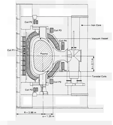
The JET electromagnetic system is made up of the toroidalandpoloidalcoils,thepurposeof whichisto establish,maintainandcontrolthetokamak magnetic configuration(seeFig.15).Itincludesthetoroidalcoils, thepoloidal coilPI,actingasprimarywindingof the tokamak transformer and thecoils P2,P3 and P4 to control plasma radial position, vertical position and shape.Inordertoperformthesefunctions,thecoilsmust be energized by suitable DC power supplies, whose voltagesandcurrentsarecontrolledinrealtimebythe plasma position and current control system (PPCC). AdditionalDCpowersuppliesenergizetheneutralbeam andradiofrequencyplasmaadditionalheatingsystems. ThetotalinstalledDCpowerrquiredbyJETiswellin excessof 1500MVAwithapeakabove1000MWand a energycontentperpulseuptolO.OOOMJ.Morethanhalf ofthepowerandoftheenergyistakendirectlyfromthe Gridat400kVandtherestisprovidedbytwovertical shaftflywheelgenerators.Consequently,amajor feature of theJET power supplyscheme isthe 400kV33kV distributionsystem.Auxiliarypowerissuppliedbythe 20MVA, 11kV3.3kV415Vdistribution system.
0 COIL3 T~f
m η
IRON "CORE
.VACUUM VESSEL
TOROIDAL COILS
R=2.96m,a=1.25m,k=%=1.68 lp=4.8MA BTO=3.45T Vp=150m3
Fig.15 Crosssection of JET showing toroidal and poloidal coils.
ThedevelopmentprogrammetobringJET,firsttoits full designperformance andsubsequently wellabove, callsforcontinuousmodificationandupgradingofthe electromagneticsystem.Thekeyobjectiveof 1987was toextend theJET operatingregimetoabove5MA in materiallimiterconfigurations and toabove 3MA in magneticlimiter ('XPoint') configurations. The JET electromagnetic system has been upgraded to allow plasmacurrentsupto 7MAwithmateriallimiter and upto4MAwithmagneticlimiter,whiledetailedstudies havebeen carried out to investigatethe feasibility of settingupXPointconfigurations approaching7MA.
Magnet System
During the 198687 shutdown, major modifications havebeencarriedoutonthemagnetsystems,asfollows: (a) twosubcoilswereadded tothepoloidal coilPI increasingthetotaltoten,withtheobjectiveofreducing strayfields atbreakdown,andthusimproving plasma startupconditions.Thisinvolveddismantlingthewhole upperpart ofthemachine (Fig.16);
(b) an additional busbar wasconnected to the six centralsubcoils(seeFig.15)toallowseparatecontrolof thecurrentinthesecoilsrelativetotheendcoils.This enabledanincreaseinavailablefluxswingbyincreasing themaximumcurrentinthecentralcoilsfrom40kAto 60kAandanimprovedflexibility incontrolofplasma shape.Thiswasmadepossiblebytaking advantageof thecenteringforceofthetoroidalcoilswhichcounteract theoutward forceof PI,when energized.
Duringthisworkadesignproblem was discovered.
H T Æ·
V 7
Technical Achievements during 1987
Fig.16 The disassembly of the top of the JET Machine to make a ten subcoil stack within the PI coil.
WhenthePIcoilwasremovedandthestackdisassem bled,someslightdamagewasobservedonthesubcoils. Keyswhichlocatedandpreventedrelativerotationofthe subcoilswerefractured duetothetorsionalactionofthe toroidalfieldcoils.Topreventreoccurrenceofthiseffect the subcoil interface was modified: the number of interlockingkeyswasincreasedfrom 1to12persubcoil and spring assemblies were fitted so that the coils returnedtotheirstartingpointaftereachpulse(Fig.17). Newequipmenttomonitorrotationaldisplacementwas alsoinstalled.Modifications werealsomadetothecoil busbarsystemtomatchpowersupplyrequirementsand tothecoilprotectionsystemtoallowasymmetricsingle Xpoint operation.
MagnetPowerSupplies
Implementationofenhancementstothepoloidalpower supplieshasbeenamajoractivity.Amodulationcircuit has been integrated into the existing poloidal circuit, leading to the new circuit shown in Fig.18. Besides previouskeyfunctions of establishingand controlling plasmacurrent,thecircuitnowmakesprovisionforthe following additions:
(a) stray fields at breakdown are further reduced (belowthelevelobtainedwiththeinstallationoftenPI subcoils), by supplying from the PFX circuit the six centralsubcoilswithaslightlylowercurrent(afewkA) than the premagnetization current (nominal value 40kA),flowing inthe endsubcoils;
(b) the rate of increase of the plasma current is controlled during theearly phaseof thepulse,bythe additionalswitchingnetwork.Thisiscomplementedby upgrading the voltage capability of the vertical field amplifiers (PVFA) with the addition of booster amplifiers;
(c) the flux swing is enhanced (up to 40Wb) by supplyingthecentralsixPIsubcoilswitha60kAcurrent from PFX (whiletheend subcoilscarry40kA);
(d) Xpoint configurations above the 1986 plasma current levels are actively established using PFX by maintaining currents up to 40kA in the central PI subcoilsabovethe valueintheend subcoils.
r ^
rgi
Ó
φ
Fig.17 Assembly of the new spring keys between the PI subcoils to improve electromechanical behaviour during operation.
Fig.18 The new poloidal circuit, showing (a) the additional switching network, (b) the PFX unit, and (c) the booster amplifiers.
Item (a) has not yet been implemented, but the remaining features are now available, except that the lOkVPVFAbooster(tobedeliveredduringearly 1988) iscurrentlyreplaced byatemporary2.8kVbooster.
Technical Achievements during 1987
withintheplannedlife oftheProject. However, anew scheme has been proposed in which a 7MA Xpoint configurationcouldbeachievedbydrivingtheupperand lowerP4coilsoutofbalancebyabout500ampereturns. Thus,additionalwindingswouldnotberequired.This schemewould alsohavetheadvantage of transferring theadditionalshearstressesonthetoroidalcoilstowards lessstressedregionsand somakeadditional structural supports unnecessary.The selected scheme shown in Fig.19, basically relieson modifications of thePVFA control scheme only. This makes the new domain of operation available by mid1988, provided the stress analysisonthecoilsprovesacceptable(assuggestedby preliminary calculations).
(ld*8kA) PVFA 3 [$|PVFAÌ.
BD5 Γϊ~
PVFBUnit A
PVFBUnitB
Fig.19 The scheme proposed for establishing Xpoint configurations up to 7 MA.
Designsfor powersupply schemes(15kA, 12kV, 010kHz)toenergizeeightsaddlecoilshavealsobeen evaluated with the help of two study contracts with major manufacturers .Thesewillbeusedto feedback stabilize the m = 2 and η = 1oscillation modes (thus preventingensuing radial disruptions).
Plasma Control
The Plasma Position and Current Control (PPCC) system has been enhanced byreplacing the analogue plasma current controller byanew digital subsystem which includesthefeedback control of the difference currentbetweenthecentralandtheendsectionsofthe PIcoil.Twosignalsaregeneratedbythissystem:onefor the excitation of the poloidal flywheel generator convenor,usedforfeedbackcontrolofthepremagnet ization current and theplasmacurrent;and the other signalisusedforvoltagecontrolofthePFX amplifier, employedforfeedbackcontrolofthePI coil difference current. The new system also includes facilities for automatic current limitation in the central and end sections of the PI coil. The system has performed successfully duringJET operation.
Detailed designhasstarted ofadualsystem for the stabilizationoftheverticalplasmaposition.Thepresent stabilization system provides an automatic feedback loopgain correction forthecasewhen oneof thetwo seriesconnected radialfield amplifiers tripsdueto an internal fault. The additional objective of the dual systemisalsotohardenthecircuitagainstsingle faults in the measurement and control section. For this purpose,verticalpositionchangesaremeasuredattwo oppositeoctantstocontrol independently thevoltage of the twoamplifiers: a 1kHz AC test signal is con tinuouslyinjectedattheinputofeachmagneticsignal amplifier andthecorrespondingACcomponentinthe twocontrolsignalsiscompared withthatof adummy channeltodiscoveranyabnormalsignaltransmission. Intheeventofafault inonemeasurement branch, the control signalof thehealthybranch isrouted to both radial field amplifiers.
Moreover, experimental tests have shown that
Technical Achievements during 1987
magnetic signal integrators can be omitted if proportional feedback control is added to the existing integral feedback control of the average radial field amplifier current, without sacrifice in stabilization
performance. This result allows a substantial
simplification of the stabilization system.
Additional Heating Power Supplies
There are three systems of additional heating power supplies (Fig.20): the neutral beam and the ion cyclotron radio frequency systems already in operation, and the lower hybrid radio frequency system at present under procurement.
There are three subsystems of the neutral beam power supplies already installed. These are the Testbed, Octant No.8 and Octant No.4 systems, of which the Testbed, with two 80 kV, 60 A beam lines operates routinely. Only six beam lines are operational in the Octant No.8 system due to both beam line and power supply problems. A fire in the protection system enclosure No.5 caused vaporization of mercury from the power supply ignitrons of one crowbar, thus making the enclosure equipment unusable. Extensive design modifications/additions have been introduced into the protection circuits and all crowbar insulators have now been replaced by non-flammable materials.
The Octant No.4 system has been completed and commissioning with PINI's has started, including all modifications already implemented in the Octant No.8 system. At present, four beam lines are under commissioning with PINI's and the whole system is scheduled for operation at the end of January 1988. A set of new power supplies (525 V, 270 A with current rates
up to 300As-1) have been designed and are under
procurement. These will energize coils for active control of stray magnetic fields inside the two PINI boxes, when operating at plasma currents up to 7 MA.
The full system of eight ICRH (Ion Cyclotron Radiofrequency Heating) Generators is operating routinely. However, during 1987, the system has been gradually upgraded by replacing all 1.5 MW tetrodes with 2.0 MW tetrodes in the RF generators. A new set of power ^ supplies has been designed to supply the drivers, while the existing power supplies (originally designed to include the drivers) will eventually supply only the output stage of the generators. Since the new driver power supplies are still under manufacture and not all the 2.0MW tetrodes are available, only three generators were operated at the new power level, using the ICRH testbed power supply to supply the three drivers as a temporary measure. The design of the new set of LHCD (Lower Hybrid Current Drive) power supplies has been completed, together with the tendering procedures, leading to the placing of two major orders, one for the main power supply and the other for the crowbars due to protect the klystrons. There will be five of these power supplies, one for the Testbed and four for the actual system. Each supply will feed four klystrons, delivering
a voltage to be regulated between -40 and -70kV at a current of 100A. Delivery will start at the end of 1988. However, the Testbed will have a temporary supply much earlier, making use (with minor modifications) of one of the neutral beam power supplies.
Power Distribution
With the 400kV system already developed to its full capacity, effort on power distribution has been fully devoted to a major extension of the AC auxiliary power system, to cope with requirements for diagnostics, electromagnetic system, additional heating, CODAS, buildings and machine services. At the end of the shutdown (June 1987), over 100 km of new cables of forty different types are installed. Activity was split into 13 major areas involving up to eighty workers.
Even after resuming operations, design and installation work continued. Major jobs included electrical services for the new building J20 and the toroidal magnet cooling water chillers. In addition, routine maintenance of the 400kV-33kV and 11 kV-3.3 kV-415 V distribution systems was carried out and a long list of small jobs was completed entailing handling of about 6,000 documents.
JET Operation
The Division is heavily involved in operation, with four (out of seven) Engineers-in-Charge, five Power Supply Operation Engineers (the same professional staff serving also as Session Leaders during Machine commission-ing), twelve Power Supply Operators, eight Additional Heating Power Supply Operators and four stand-by electricians and fitters. Moreover, the Division also provides an Electrical Engineer on-call service throughout the year, with six people involved in these duties. These operational duties are additional to the continuing key role of the Divisional staff in the implementation of the Project Development Plan, which still requires the placing and managing of a large number of maj or contracts each one preceded by the appropriate design work.
Of the new systems made operational during 1987, each have met the design performance, as follows:
(a) The PI coil stack, with 10 subcoils, have allowed stray fields to be reduced by more than a factor of two, which, in conjunction with the additional switching network and the temporary PVFA booster, has made 22 kV, 40 kA premagnetization breakdown possible, thus allowing good plasma start-up in the required scenarios;
(b) the PFX scheme, with the four busbar connection to the PI coils, has allowed an increase in the flux swing, so that plasma currents of 5MA for 10s and of 6MA for 2 s could be sustained. X-point configurations up to 3.5 MA plasma currents for more than 8s have been established. It has also permitted greater flexibility in plasma shape control.
Future Activities
TechnicalAchievementsduring1987
(i)MagnetSystem
(a) implementationoftheschemefortheextension of Xpoint operation upto 7MA(seeFig.19),which impliesanewPVFAandBoosterlayout(toallow for independent control of the upper and lower P4 coil current), a new control device, additional machine protections,additionstoDMSS(DirectMagnetSafety System),newfeatures inthe PPCC and anextensive systemanalysisinbothoperationalandfaultconditions;
(b) extensionofthecurrentcapabilityofthevertical fieldamplifiers(PVFA),theshapingamplifers(PSFA) andPFX,ifnecessary,to40kA, 15s;
(c) upgradingPFXinvoltagebyusingexistingpower supply (PVFA2)asabooster;
(d) digitizationoftheplasmapositioncontroland implementationofthedualcontrolsystemfor PRFA (PoloidalRadialFieldAmplifiers),tomakeavailabletwo fully independent systems for controlling vertical instabilities. It is also proposed to implement an automaticreductionofdestabilizing shapingcurrents intheeventofreachingstabilizationlimits;
(e) completionoftestsonthetoroidalprototypecoil toassessultimateshearstresscapabilitiesofelectrical insulation andbondingmaterial;
(f) completion of engineering analysis, aided by computercodes,for thestressesonbothtoroidaland poloidalcoilsinthenewoperatingscenarios;
(g) detaileddesign,tenderspecificationsandcontract procedures for the power supplies for the feedback controlofthe m=2and η=1 modes,whenadecision toproceedistaken;
(h) tendertechnicalspecificationandcontractproc eduresfortheactiveandreactivepowercompensation systems to shield the Grid from excessive demand expectedbytheimplementationofallJETnewfeatures;
(i) specification andprocurementofinductorsand resistances required for the active stray field compensationcircuit (seeFig.18);
(j) improvement inreliability ofpowersuppliesby
better maintenance procedures and design mod
ifications;
(ii)AdditionalHeating
(k) ontheNBsystems,completionofmodifications requiredinthepowersuppliestoimprovereliabilityand availability;installationandcommissioningofthepower suppliesforstrayfieldcompensationinthePINIbox; procurementofallthenecessarycomponentsfor160kV operation;
(1) installation and commissioning of the power suppliesfortheupgradeof ICRHdrivers;
(m) supervision of contracts for LHCD power
suppliesandinstallationofthefirstunitbeforetheend of1988;
(n) modification of apair of neutral beam power suppliestobeused, onalternativeweeks,for neutral beamsor for theLHCDtestbed;
(o) routinemaintenance;
(iii)PowerDistribution
(p) procurementinstallationandcommissioningof newcubiclesand cabling for pellet injection, remote handling,LHCD,J20andJ25buildings,lightingin 32, J4andJ1H;
(q) fullimplementationoftheearthingofallmetallic structuresintheTorusHall;
(r) routine maintenance of the 400kV33kV and HkV3.3kV415V distributionsystems;
(iv)JETOperation
(s) commissioningonJETofallnewequipmentdue tocomeintooperation, asitemizedabove;
(t) servingasSessionLeaders,EngineersinCharge, Power Supply Operation Engineers and other oper ationaldutiesasmentionedpreviously.
Neutral
Beam
Heating
System
Following the very successful first year of neutral injection experimentsduring 1986,1987provedtobe moredifficultandasomewhatdisappointingperiodin termsofinjectionintothetokamak.Duringthemajor 1987shutdownperiod,aconsiderableamountofwork involvingplannedimprovementsandmodificationsto boththeOctantNo.8andNo.4injection systemswere successfully completed. Subsequently, three separate
major hardware failures occurred during the
commissioning(andrecommissioning)oftheOctant No.8injectionsystem.Thesefaultswhicharedescribed belowwerenotassociatedwithactualbeamoperation andtheyoccurredattimesduringwhichnovoltagewas appliedtothebeamsources,andhencenopowerwas being extracted.
Work in the N.B. Testbed has continued both in support of the injection systems installed on the tokamakand,inconjunctionwithfurtherdevelopment ofhighheattransferelements.Considerableupgrading of thecryogenicplant wassuccessfully completed to allow routine simultaneous operation of three large cryopumpsplusadditionalliquidheliumsupplies(i.e. fortheOctantNo.8andNo.4N.B.systemsandforthe pelletinjectionsystem).
NeutralBeamOperations
NeutralBeaminjectionintothetokamakwasseverely curtailedduring 1987,duetoaseriesoffaults,noneof whichwasdirectlyrelated toactual operation of the beamsystem.