“ I hereby declare that I have read this fully report entitled “Modified PID Controller for DC-DC Buck Converter using Voltage Based PWM” and found that it has comply the partial fulfilment for awarding the Bachelor of Electrical Engineering (Power Electronic and Drives)”
Signature :………..
Supervisor’s Name :
I declare that this report entitled “Modified PID Controller for DC-DC Buck Converter using Voltage Based PWM” is the result of my own research except as cited in the references. The report has not been accepted for any degree and not concurrently submitted in candidature of any other degree.
Signature : ………
Name : SHARUL AIDY BIN MUHAMMAD NOR ZAINI
MODIFIED PID CONTROLLER FOR DC-DC BUCK CONVERTER
USING VOLTAGE BASED PWM
SHARUL AIDY BIN MUHAMMAD NOR ZAINI
A report submitted in partial fulfilment of the requirement for the degree of Bachelor
of Electrical Engineering (Power Electronic and Drives)
Faculty of Electrical Engineering
iv
ACKNOWLEDGEMENTS
Firstly, my biggest thanks to Allah S.W.T who gave me the opportunity in doing this project and always giving me hope and ways in completing the tasks.
My great appreciation goes to my supervisor, Pn. Azrita Binti Alias for her guidance, knowledge, skill and patience in helping her final year students for the past two semesters.
v
ABSTRACT
vi
ABSTRAK
vii
TABLE OF CONTENTS
CHAPTER TITLE PAGE
ACKNOWLEDGEMENT iv
ABSTRACT v
ABSTRAK vi
TABLE OF CONTENTS vii
LIST OF FIGURES ix
LIST OF TABLES xi
NOMENCLATURE xii
1 INTRODUCTION
1.1 Research Background 1
1.2 Problem Statement 2
1.3 Objectives 2
1.4 Scopes of Project 2
1.5 Report Outline 3
2 LITERATURE REVIEW
2.1 Theory and Basic Principles 4
2.2 Review of previous related works 16 2.3 Summary and discussion of the review 17
3 RESEARCH METHODOLOGY
viii
4 RESULTS AND DISCUSSION
4.1 Open Loop 30
4.2 Conventional PID Controller 35
4.3 Modified PID Controller 49
4.4 Overall controller comparative analysis 61
5 CONCLUSION AND RECOMMENDATION 62
REFERENCES
ix
LIST OF FIGURES
NO. TITLE PAGE
2.1 PID Controller Block Diagram 12
3.1 Buck Converter Circuit 18
3.2 Switch Off Circuit 19
3.3 Switch On Circuit 19
3.4 Buck Converter Modelling 22
3.5 Basic PID Control System 25
3.6 Specific PID Block Diagram 26
3.7 Modified PID architecture in MATLAB rltool 26
4.1 Buck Converter electrical circuit in Simulink 31
4.2 Buck Converter electrical circuit output voltage 31
4.3 Buck Converter Block Diagram circuit 32
4.4 Buck Converter Block Diagram subsystem 32
4.5 PWM Block Diagram subsystem 33
4.6 Voltage output in block diagram simulation 33
4.7 Step response of open loop buck converter in MATLAB rltool 34 4.8 Compensator editor adjusted for PI Controller in rltool 36 4.9 Root locus of plant after being feedback by a PI Controller 37
4.10 Step response of first PI Controller 37
4.11 Step response of second PI Controller 38
4.12 Step response of third PI Controller 38
4.13 Step response of fourth PI Controller 39
4.14 Step response of fifth PI Controller 40
4.15 Compensator editor adjusted for PID Controller in rltool 42 4.16 Root locus of plant after being feedback by a PID Controller 42
4.17 Step response of first PID Controller 43
4.18 Step response of second PID Controller 44
x
4.20 Step response of fourth PID Controller 46
4.21 Step response of fifth PID Controller 47
4.22 Compensator editor adjusted for I-D Controller in compensator 1 49 using rltool
4.23 Compensator editor adjusted for I-D Controller in compensator 2 50 using rltool
4.24 Root locus of plant after being feedback by an I-D Controller 50
4.25 Step response of first I-D Controller 51
4.26 Step response of second I-D Controller 51
4.27 Step response of third I-D Controller 52
4.28 Compensator editor adjusted for PI-D Controller in compensator 1 53 using rltool
4.29 Compensator editor adjusted for PI-D Controller in compensator 2 54 using rltool
4.30 Root locus of plant after being feedback by a PI-D Controller 54
4.31 Step response of first PI-D Controller 55
4.32 Step response of second PI-D Controller 55
4.33 Step response of third PI-D Controller 56
4.34 Compensator editor adjusted for PD-I Controller in compensator 1 57 using rltool
4.35 Compensator editor adjusted for PD-I Controller in compensator 2 58 using rltool
4.36 Root locus of plant after being feedback by a PD-I Controller 58
4.37 Step response of first PD-I Controller 59
4.38 Step response of second PD-I Controller 59
xi
LIST OF TABLE
NO. TITLE PAGE
2.1 Parameter Adjustment Effect 14
3.1 Timeline for milestones 28
4.1 Buck converter parameter 30
xii
NOMENCLATURE
IEEE - Institute of Electrical and Electronic Engineers
MATLAB - Matrix Laboratory
PD - Proportional-Derivative
PI - Proportional-Integral
PID - Proportional-Integral-Derivative
CHAPTER 1
INTRODUCTION
1.1 Research Background
The general purpose of power electronic converter is converting electrical energy from one form into another. The main aim includes enabling the electrical energy to reach the load in top efficiency. Besides, the usage of power electronic aids in reducing the size of the device to convert these energy, thus cutting the implementation cost. In this project, the power electronic device that has been used is a dc to dc converter. Dc to dc converter includes:
i. Buck ii. Boost iii. Buck-boost
Buck converter has been chosen to be used for this project. The buck converter converts an unregulated dc input into a controlled dc output within desired voltage value. Buck converter is also known as the step down converter. This is due to its circuit characteristic of steeping down the unregulated input voltage into a smaller output voltage. In this project, the buck will step down the input voltage 9 𝑉𝑑𝑐 to 5 𝑉𝑑𝑐 using switching frequency of 50kHz. The buck converter circuit is connected together with a controller in order to control the behaviours of the system in linear. This system is regarded as a close loop system with feedback. MATLAB Simulink software has been used to run all the simulations.
2
1.2 Problem Statement
The output voltage (𝑉𝑜) of buck alone is undeniably stable. Nevertheless, within seconds of the operation of the buck converter, the voltage value shows overshoot and a steady-state error. Moreover, other criteria that must be concerned includes the rise time and settling time in order to obtain the desired output in its peak efficiency. Let alone a dc-dc buck converter operates without a specific controller, the rise time is too long before it reaches the steady-state condition. The overshoot is high and the settling time is high due to the output oscillation that is too long. As for the steady-state error, sometimes the output of the buck converter alone does not reach the desired value that has been calculated mathematically.
1.3 Objectives
1.3.1 To propose a modified PID as a feedback control system to address issues of step-changes in reference and load for dc-dc buck converter
1.3.2 To compare the system’s responses between the conventional PID, PI and the proposed modified PID controller
1.4 Scopes of Project
1.4.1 Literature review on dc-dc converters, PWM switching and feedback controllers 1.4.2 Obtain a mathematical model of dc-dc buck converter
1.4.3 Design and simulate the PWM switching pattern of dc-dc buck converter 1.4.4 Design and simulate the conventional PID, PI and the modified PID controllers 1.4.5 Analyse and compare the results of conventional PID, PI and modified PID
3
1.5 Report Outline
The contents of the report is classified as follows:
Chapter 1 describes the overview of the entire project, research background, problem statement, objectives, scope and the expected outcome of the project.
Chapter 2 elaborates the literature review related to the project. This includes study of dc-dc converter, controllers, tuning method and limitations in tuning. Each of the facts and analysis is described based on comprehensive study in reference to various reliable materials and previous researches. The information collected includes from IEEE journals, articles, books and technical papers.
Chapter 3 explains the methodology of the project and covers the methods and procedures that have been used in carrying out the entire project. In this chapter, the Gantt Chart for the whole 2 semesters of duration that the project has been carried out is explained briefly.
Chapter 4 highlights the results obtained from all the simulations. Analysis for open-loop buck converter system, closed-loop system using conventional and modified PID are made. Also, the comparative analysis to justify the controller that suits best to enhance the performance of buck converter optimally. Discussions and deep analysis are done and noted.
Chapter 5 concludes the study achievement and proposed some recommendations
4
CHAPTER 2
LITERATURE REVIEW
2.1 Theory and basic principles
2.1.1 DC-DC Converter
In order to step down a voltage from one value to another, a transformer can always be used. But, a buck converter is more suitable to be used because of the ability of switching converter to provide isolation of noise, power bus regulation and so on. A dc-dc converter may change the voltage level into desired value depending on the value of resistance, inductance and capacitance in the circuit. Meaning, the desired voltage level can be obtained by manipulating the value of those criteria stated. In this project, the operation of the system need to be fully analysed.
2.1.2 PWM and Switching
5
2.1.3 Feedback Control Systems
A feedback control system can be described as a system that retains a specified relationship between the output and reference input using comparison and use the differences as a mean of control method. For instance, a temperature control system in a room. The actual room temperature is measured and then compared with the reference temperature (desired temperature). Then, the thermostat switch between cooling or heating equipment on and off so that the temperature in the room reach its desired level, in spite of the outside conditions.
2.1.4 Closed-Loop Control System
Feedback control systems are often referred to as closed-loop control systems. The terms feedback control and closed-loop control are used interchangeably because of their significance. In a closed-loop system the actuating error signal, which is the difference between the input signal and the feedback signal (which may be the output signal itself or a function of the output signal and its derivatives and/or integrals), is fed to the controller so as to reduce the error and bring the output of the system to a desired value. The term closed-loop control always implies the use of feedback control action in order to reduce system error.
2.1.5 Open-Loop Control System
Open-loop control system can be interpreted as a system where the output is not subjected into any control method. In other words, the output value is not measured for comparison with any reference input or fed back in an open-loop control system. Washing machine can be a perfect example to elaborate open-loop control system. It involves soaking, washing and rinsing. All the operations are based on time. Hence, it is clear that the machine does not measure the output signal, which is, the cleanliness of the clothes.
6
Hence, the accuracy of the system depends on calibration. However, in case any undesired noise or disturbance occur, an open-loop system will fail to perform its desired task. Practically, the open-loop system is highly recommendable when the relationship between the input and output are known and when there are no presence of internal or external disturbances. Clearly, such systems are not feedback control systems. Note that any control system that operates on a time basis is open loop.
2.1.6 Closed-Loop versus Open-Loop Control Systems
An advantage of the closed-loop control system is the fact that the use of feedback makes the system response relatively insensitive to external disturbances and internal variations in system parameters. It is thus possible to use relatively inaccurate and inexpensive components to obtain the accurate control of a given plant, whereas doing so is impossible in the open-loop case.
Taking stability as the point of view, it is easier to create an open-loop control system. This is due to system stability is not a major problem in an open-loop system. Meanwhile, it is a major problem in a closed-loop control system, which may tend to overcorrect errors and thereby can cause oscillations of constant or changing amplitudes.
7
2.1.7 Proportional Integral Derivatives
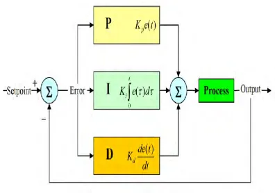
A proportional-integral-derivative controller (PID controller) is a comprehensive control loop feedback mechanism widely used in industrial control systems. The operation of PID controller can be deemed simple yet powerful. First, the desired set point must be given. It will adjust the error between the measured process variable and the desired set point by calculating them and provides adjustment or corrective action. There are three separate parameters in the PID controller algorithm. Those are the Proportional, Integral and Derivative values. The Proportional value determines the reaction to the current error, the Integral determines the reaction based on the sum of recent errors and the Derivative determines the reaction to the rate at which the error has been changing. The process is then adjusted via a control element subjected to all those three total summation such as the position of a control valve or the power supply of a heating element. An accurate desired output responses that meets the process requirement can be achieved by properly ‘tune’ the three constants in the PID controller algorithm. PID controller can always be changed into a PI or PD controller, depending on the parameters of the PID algorithm used. Meaning, for a PI controller, proportional and integral terms are used with the absence of derivative value. PD controller is simply a PID without the integral value. Note that the PID stated is the conventional type, meaning, the architecture of all three algorithm parameters is shown as Figure 2.1. A modified PID is simply a PID controller with a modification in the architecture of the parameters.
2.1.7.1 Proportional term
The proportional term provides changes to the output that is proportional based on the error value. Proportional gain, Kp will be multiplied with the error so that the proportional response can be modified.
The proportional term is given by:
8
Where
- 𝑃𝑜𝑢𝑡: Proportional output
- 𝐾𝑝: Proportional Gain, a tuning parameter - e: Error = SP – PV
- t: Time or instantaneous time (the present)
-For a given change in error, a high proportional gain results in a large change in the output. However, if the proportional gain is too high, the system itself may become unstable. In contrast, a small gain results in a small output response to a large input error, and a less responsive (or sensitive) controller. Meaning, extremely small proportional gain will not provide desired control action as it may be too small when responding to system disturbances.
In the absence of disturbances pure proportional control will not settle at its target value, but will retain a steady state error that is a function of the proportional gain and the process gain. Despite the steady-state offset, both tuning theory and industrial practice indicate that it is the proportional term that should contribute the bulk of the output change.
2.1.7.2 Integral term
The contribution from the integral term is proportional to both the magnitude of the error and the duration of the error. Summing the instantaneous error over time (integrating the error) gives the accumulated offset that should have been corrected previously. The accumulated error is then multiplied by the integral gain and added to the controller output. The magnitude of the contribution of the integral term to the overall control action is determined by the integral gain, 𝐾𝑖.
The integral term is given by:
9
Where
- 𝐼𝑜𝑢𝑡: Integral output
- 𝐾𝑒: Integral Gain, a tuning parameter · e: Error = SP − PV
· τ: Time in the past contributing to the integral response
The integral term speed up the movement of the process towards set point and eliminates the residual steady-state error that occurs with a proportional only controller. Meaning, in the case of buck converter, the integral term enables the output response to reach its rise time and settling time faster. But, since the integral term is responding to accumulated errors from the past, it can cause the present value to overshoot the set point value (cross over the set point and then create a deviation in the other direction). Section loop tuning further elaborates integral gain tuning and controller stability.
2.1.7.3 Derivative term
The derivative gain, 𝐾𝑑 is defined as the magnitude of the contribution of the derivative term to the overall control action. The rate of change of the process error is calculated by determining the slope of the error over time (i.e. its first derivative with respect to time) and multiplying this rate of change by the derivative gain 𝐾𝑑.
The derivative term is given by:
𝐷𝑜𝑢𝑡 = 𝐾𝑑𝑑𝑒𝑑𝑡 (2.3)
Where
- 𝐷𝑜𝑢𝑡: Derivative output
- 𝐾𝑑: Derivative Gain, a tuning parameter - e: Error = SP − PV
10
The derivative term slows the rate of change of the controller output and this effect is most noticeable close to the controller set point. Hence, derivative control is used to reduce the magnitude of the overshoot produced by the integral component and improve the combined controller-process stability. However, differentiation of a signal amplifies noise in the signal and thus this term in the controller is highly sensitive to noise in the error term, and can cause a process to become unstable if the noise and the derivative gain are sufficiently large.
[image:22.595.107.504.320.598.2]Figure 2.1 shows the implementation of a PID controller on a certain plant. The proportional, integral and derivatives terms are summed up together to feed the plant, based on the calculated error gained from the feedback.
11
2.1.8 Tuning Method
Controller tuning is a very important step in a closed-loop control systems. In case of PID controller, all the proportional, integral and derivative gains parameters need to be choose wisely or else, the overall process might become unstable and further damages the system itself. To tune a control loop means to adjust all the controls parameters as stated, which are proportional, integral and derivative values accurately so that the desired control response can be obtained.
There are several indicators that need to be fulfilled before attempting to tune a controller. As for PID, these include overshoot, rise time, settling time and others. For example, in case a process with an overshoot would harm the entire device, then eliminating the overshoot comes as a priority and hence, the gains need to be adjusted accordingly. Another example might be process to minimize energy expended in reaching a new set point. In general, stability of response (the reverse of instability) is required and the process must not oscillate for any combination of process conditions and set points.
Some processes have a degree of non-linearity and so parameters that work well at full-load conditions do not work when the process is starting up from no-load. This section describes some traditional manual methods for loop tuning.
12
2.1.8.1 Ziegler-Nichols method
Even though the PID controller has been reportedly used in industry since the early 1900’s, a systematic tuning strategy, was only proposed in the 1940’s. The Ziegler-Nichols is the earliest tuning method introduced for the controller. Ziegler and Nichols suggested rules for tuning PID controllers (meaning to set values Kp, Ti and Td) based on experimental step responses or based on the value of K that results in marginal stability when only proportional control action is used. Ziegler-Nichols rules, which are briefly presented in the following, are useful when mathematical models of plants are not known. (These rules can, of course, be applied to the design of systems with known mathematical models.) Such rules suggest a set of values of K, Ti and Td, that will give a stable operation of the system. However, the resulting system may exhibit a large maximum overshoot in the step response, which is unacceptable. In such a case we need series of fine running until an acceptable result is obtained. In fact, the Ziegler-Nichols tuning rules give an educated guess for the parameter values and provide a starting point for fine tuning rather than giving the final settings for K Ti and Td in a single shot.
2.1.8.2 Pole-Placement Method
The pole-placement method has been used mostly for a low order system, i.e. system with two order or below. The approach is to adopt a general second-order model as in equation below and to specify a desired damping ratio, 𝜍 and natural frequency, 𝜔 for the system
𝑠2 + (2𝜍𝜔)s + 𝜔2 = 0 (2.4)
Its 𝐾𝑝 and 𝐾𝑖 values with the specified damping ratio and natural frequency can be obtained by comparing equation above with the characteristics equation of the closed-loop system transfer function. For example, consider the first system with a transfer function of