UNIVERSITI TEKNIKAL MALAYSIA MELAKA
THE EFFECT OF PISTON HEAD ON THE PERFORMANCE OF
ENGINE
This report submitted in accordance with requirement of the UniversitiTeknikal Malaysia Melaka (UTeM) for the Bachelor Degree of Engineering Technology
Automotive
(Department of Mechanical Engineering Technoogies) (Hons.)
by
AZIZUL HAKIM BIN KAMARDIN B071210483
890727-04-5283
UNIVERSITI TEKNIKAL MALAYSIA MELAKA
BORANG PENGESAHAN STATUS LAPORAN PROJEK SARJANA MUDA
TAJUK: THE EFFECT OF PISTON HEAD ON THE PERFORMANCE OF ENGINE
SESI PENGAJIAN: 2015/16 Semester 2
Saya AZIZUL HAKIM BIN KAMARDIN
mengakumembenarkanLaporan PSM inidisimpan di PerpustakaanUniversitiTeknikal Malaysia Melaka (UTeM) dengansyarat-syaratkegunaansepertiberikut:
1. Laporan PSM adalah hak milik Universiti Teknikal Malaysia Melaka dan penulis. 2. Perpustakaan Universiti Teknikal Malaysia Melaka dibenarkan membuat salinan
untuk tujuan pengajian sahaja dengan izin penulis.
3. Perpustakaan dibenarkan membuat salinan laporan PSM ini sebagai bahan pertukaran antara institusi pengajian tinggi.
4. **Silatandakan ( )
SULIT
TERHAD
TIDAK TERHAD
(Mengandungimaklumat yang
berdarjahkeselamatanataukepentingan Malaysia sebagaimana yang termaktubdalam AKTA RAHSIA RASMI 1972)
(Mengandungimaklumat TERHAD yang telahditentukanolehorganisasi/badan di mana penyelidikandijalankan)
(TANDATANGAN PENULIS)
AlamatTetap:
Bt 10 Kg Pulau
76100 Durian Tunggal
Melaka, Tarikh: ________________________ Disahkanoleh: (TANDATANGAN PENYELIA) Cop Rasmi: Tarikh: _______________________
** JikaLaporan PSM ini SULIT atau TERHAD,
iii
DECLARATION
I hereby, declared this report entitled “The Relation Between Piston Head With Performance” is the results of my own research except as cited in references.
Signature :………
Name : Azizul Hakim Bin Kamardin
iv
APPROVAL
This report is submitted to the Faculty of Engineering Technology of UTeM as a partial fulfillment of the requirements for the degree of Bachelor of Engineering Technology (Department of Mechanical Engineering Technologies) (Hons.). The member of the supervisory is as follow:
v
ABSTRACT
Piston is one of the important components in the system dalam.Piston combustion engine acts as the transmitter power value resulting from the burning of fuel and air mixture in the combustion chamber. Nowadays there are various forms produced by the form piston head piston.
The objective of this study was to examine the engine performance in horsepower and torque produced by the different shape of the head piston in an internal combustion engine which consists of 3 types of piston domes, mugs, and standard.
Experiments carried out using an internal combustion engine mounted on Honda EX5. The engine will run on a chassis dynamometer testing to determine the results. Piston performance will be evaluated based on the maximum available torque, maximum horsepower.
vi
ABSTRAK
Piston merupakan salah satu komponen yang penting dalam sistem enjin pembakaran dalam.Piston berperanan sebagai ajen penghantar kuasa yang terhasil daripada proses pembakaran campuran minyak dan udara didalam kebuk pembakaran. Pada masa kini terdapat pelbagai bentuk piston yang dihasilkan berdasarkan bentuk kepala piston.
Objektif kajian ini dijalankan adalah untuk mengkaji prestasi enjin dalam kuasa kuda dan daya kilas yang dihasilkan oleh bentuk kepala piston yang berbeza dalam enjin pembakaran dalaman yang terdiri daripada 3 jenis kubah omboh, cawan, dan standard.
Eksperimen dijalankan menggunakan enjin pembakaran dalaman yang dipasang di Honda EX5 . Enjin akan berjalan dalam ujian chasis dinamometer untuk menentukan keputusan. Prestasi omboh akan dinilai berdasarkan tork ada maksimum, kuasa kuda maksimum.
vii
DEDICATIONS
I dedicate this thesis to my beloved parents who have been supporting and giving encouragement to the full during the period of my studies hard to produce this thesis.
viii
ACKNOWLEDGMENTS
I want to thank my parent who always support me in my studies and life, never tired of giving encouragement and incentive in the process of producing this report thesis.
ix
TABLE OF CONTENTS
DECLARATION ... iii
APPROVAL ... iv
ABSTRACT ... v
ABSTRAK ... vi
DEDICATIONS ... vii
ACKNOWLEDGMENTS ... viii
TABLE OF CONTENTS ... ix
LIST OF FIGURES ... xiii
LIST OF TABLE ... xv
LIST OF SYMBOLS AND ABBREVIATIONS ... xvi
CHAPTER 1 ... 1
1.0 Introduction ... 1
1.1 Background ... 1
1.2 Objective ... 2
1.3 Problem Statement ... 2
1.4 Work Scope ... 2
CHAPTER 2 ... 3
2.0 Introduction ... 3
2.1 Internal Combustion Engine ... 3
x
2.2 Piston ... 6
2.2.1 Piston Head Design ... 6
2.2.2 Design The Piston of Internal Combustion Engine... 7
2.2.3 Squish Piston ... 8
2.3 Material ... 10
2.3.1 Aluminium Alloys ... 10
2.4 Compression Ratio ... 11
2.4.1 Compression Ratio Control ... 13
2.5 Flow Analysis ... 14
2.5.1 Tumble Flow Analysis ... 14
2.5.2 Small Eddy Turbulance in Spark Ignited ... 16
2.5.3 Effect Of Engine Speed on In-Cylinder Tumble Flows ... 16
2.5.4 Turbulent Flow Structures ... 17
2.5.5 In-cylinder Flow Characteristics ... 18
2.5.6 In-cylinder Flow ... 19
CHAPTER 3 ... 21
3.0 Introduction ... 21
3.1 Flow Chart ... 21
3.2 Gantt Chart ... 22
3.3 Inspection Checklist ... 23
3.4 Before Experimental ... 23
xi
3.6 Top Overhaul/Change Piston ... 26
CHAPTER 4 ... 29
4.0 Introduction ... 29
4.1 Result ... 29
4.1.1 Piston Dimension ... 29
4.1.2 Progress Activities ... 31
4.1.3 Standard Piston ... 32
4.1.4 Standard Piston with 1.5mm Gasket ... 34
4.1.5 Low Compression Piston ... 37
4.1.6 High Compression Piston ... 39
4.2 Discussion ... 42
4.2.1 Standard Piston and Standard Piston with 1.5mm Gasket ... 42
4.2.2 Power ... 44
4.2.3 Torque ... 47
CHAPTER 5 ... 50
5.0 Introduction ... 50
5.1 Summary of Research ... 50
5.2 Achievement of Experimental ... 51
5.3 Significance of Research ... 51
5.4 Suggestion for Future Work ... 51
APPENDIX A ... 53
APPENDIX B ... 56
xii
xiii
LIST OF FIGURES
Figure 2.1: 4-Stroke Engine Cycle ... 4
Figure 2.2: Otto Cycle P-V & T-s Diagrams ... 5
Figure 2.3: Piston Head Design ... 7
Figure 2.4: Piston Temperature Distribution ... 8
Figure 2.5: CFD Computation ... 9
Figure 2.6: Thermal Test on Material (Singh & Sharma, 2014) ... 11
Figure 2.7: Thermal Efficiency Graph(Yüksek et al., 2013) ... 12
Figure 2.8: In-cylinder Pressure Curves(Yüksek et al., 2013) ... 12
Figure 2.9: Concept of Compression Ratio Control Map(Tanaka et al., 2007) ... 13
Figure 2.10: The Ensemble Average Vector for Dome Piston(Krishna & Mallikarjuna, 2009) ... 14
Figure 2.11: The Ensemble Average Vector for Dome Cavity Piston(Krishna & Mallikarjuna, 2009) ... 15
Figure 2.12: The Ensemble Average Vector for Flat Piston(Krishna & Mallikarjuna, 2009) ... 15
Figure 2.13: Tumble Ratio ... 16
Figure 2.14: Schematic Influence Of The Tumble Control Flap Position ... 17
Figure 2.15: Pisotn Head Shape ... 18
Figure 2.16: In-cylinder spray flow visualization(Kim et al., 2000) ... 19
Figure 2.17: Piston Top Shape And Expected Flow Pattern(Okura et al., 2014) ... 20
Figure 3.1: Flow Chart ... 21
Figure 3.2: Dynamometer Machine ... 25
Figure 3.3: “T” Marking on The Magnet ... 26
Figure 3.4: “T” Marking on The Timing Chain Sprocket... 26
Figure 3.5: Engine Head ... 27
Figure 3.6: Engine Block ... 27
Figure 3.7: Piston & Gasket ... 28
Figure 4.1: Piston Dimension ... 29
Figure 4.2: Power of Standard Piston ... 32
Figure 4.3: Torque of Standard Piston ... 33
Figure 4.4: Power of Standard Piston (1.5mm Gasket) ... 34
Figure 4.5: Torque of Standard Piston (1.5mm Gasket) ... 35
Figure 4.6: Power of Lower Compression Piston ... 37
Figure 4.7: Torque of Low Compression Piston ... 38
Figure 4.8: Power of High Compression Piston ... 39
Figure 4.9: Torque of High Compession Piston ... 40
xiv
Figure 4.12: Power of 3rd Gear ... 44
Figure 4.13: Power of 4th Gear ... 45
Figure 4.14: Torque of 3rd Gear ... 47
xv
LIST OF TABLE
Table 3.1: Gantt Chart ... 22
Table 3.2: Inspection Checklist ... 23
Table 3.3: Dynamoter Data ... 25
Table 4.1: Piston Dimension ... 30
Table 4.2: Progress Activities ... 31
Table 4.3: Power of Standard Piston ... 32
Table 4.4: Torque of Standard Piston ... 33
Table 4.5: Power Of Standard Piston(1.5mm Gasket) ... 35
Table 4.6: Torque of Standard Piston(1.5mm Gasket)... 36
Table 4.7: Power of Low Compression Piston ... 37
Table 4.8: Torque of Low Compression Piston ... 38
Table 4.9: Power of High Compression Piston ... 40
Table 4.10: Torque of High Compression Ratio ... 41
Table 4.11: Power at Standard Piston and Standard Piston 91.5mm Gasket) ... 42
Table 4.12: Torque of Standard Piston and Standard Piston (1.5mm Gasket)... 43
Table 4.13: Power at 3rd Gear... 45
Table 4.14: Power at 4th Gear ... 46
Table 4.15: Torque at 3rd Gear ... 47
xvi
LIST OF SYMBOLS AND ABBREVIATIONS
ICE = Internal Cobustion Engine
TDC = Top Dead Center
BDC = Bottom Dead Center
K = Kelvin
KW = KiloWatt
C.R = Compression Ratio
GDI = Gasoline Direct Injection
ROHR = Rate Of Heat Release
km = Kilometer
kPa = KiloPascal
Nm = Newom.meter
bhp = Brake horsepower
SP = Standard Piston
SP(1.5) = Standard Piston with 1.5mm Gasket
LCP = Low Compression Piston
HCP = High Compression Piston
1
CHAPTER 1
INTRODUCTION
1.0 Introduction
Internal combustion engine is the most popular used nowadays in our vehicle. In this chapter will focus on one of the important part in the ICE it is piston. The piston used can effect the engine performance.
1.1 Background
The purpose of this project is to study the types of piston used in internal combustion chamber. As we know, piston is one of the important part in the engine either there is diesel or petrol engine. The pistons have many types of design and material used in market according to the usage. The function of the piston in the engine used to compress the air fuel mixture in the engine before the mixture burned.
The piston was designed according to the usage relate with the performance needed. In the market there have many type of piston that called high compression piston, standard piston, and low compression piston. The different of these three pistons are the shape of piston head. The different of these three designed will be effect the performance of the engine in term of power, horsepower, torque, the engine speed and fuel consumption.
2
1.2.1 To study the relation between the shape of piston head with the horsepower
1.2.2 To study the relation between the shape of piston head with the torque.
1.3 Problem Statement
There is confusion among consumers regarding the piston available in the market. Each piston being used must be appropriate to the user’s daily use. This can help to increase the engine life time and the performance.
1.4 Work Scope
3
CHAPTER 2
LITERATURE REVIEW
2.0 Introduction
This chapter will discuss mainly on the theory and current development in piston head design and the effect of the piston head shape in the internal combustion engines.
2.1 Internal Combustion Engine
An internal combustion engine (ICE) is heat engine that produces the power or work from the burning the air fuel mixture in the combustion chamber. In an internal combustion engine the expansion of the temperature and high-pressure gases produced by combustion apply direct force to some component of the engine.
In an internal combustion engine the expansion of the high-temperature and high-pressure gases produced by combustion apply direct force to some component of the engine.
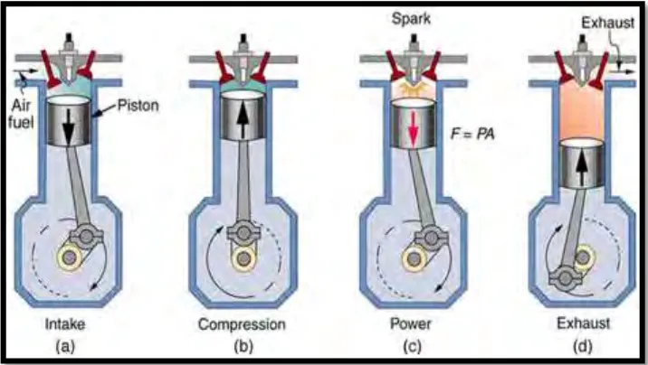
2.1.1 4-Stroke Engine
4
are intake, compression, power and exhaust. The crankshaft makes two complete revolutions to complete the four piston strokes. This makes the engine a four stroke-cycle engine. It is also called a four strokes or four-stroke-cycle engine. (Hacisevki, n.d.)
[image:20.595.155.513.402.604.2]Every movement of the piston from top dead center to bottom dead center or from bottom dead center to top dead center, known as cycles. For the movement from top dead center to bottom dead center known as intake cycle, which the air fuel enter into the combustion chamber when the intake valve opened. Then the piston will move from bottom dead center to top dead center. The air fuel in the combustion chamber will compress due to closed valve for both and those known as compression cycle. For the power cycle, the spark plug will ignite the spark and the compressed air fuel burnt. The power produced by burning process the piston pushed from top dead center to bottom dead center. For the last cycle, the piston will move from the bottom dead center to top dead center and the burning air fuel will flow out from the combustion chamber through the opened exhaust valve.
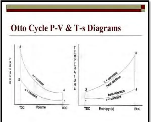
5 2.1.2 Otto Cycle
The Otto cycle consists of four internally reversible cycles, that describe the process of an engine.
[image:21.595.185.484.283.525.2]The thermal efficiency of the Otto-cycle increases with increasing compression ratio. When the Otto cycle is analyzed on a cold air standard basis an expression relating the compression ratio, temperature and pressure is obtained from isentropic properties. The compression ratio is a ratio of the volume displaced by the piston.
6
One of the important parts in internal combustion engine is the piston which used to convert the chemical energy after air fuel burning process into mechanical energy. The purpose of the piston is to help in conveying the gasses to crankshaft without loss of gas and the first part to begin a movement to transmit power to the crankshaft as a result of the pressure and energy generated by the combustion of fuel(Gupta & Tripathi, 2014).
The piston has a direct connection to the connecting rod and its free action at bottom side. At the top of piston known as piston head or crown at this part the piston will work at high pressure and temperature. Piston ring is one of the important components of the piston that provide a seal between the cylinder and the piston. The piston ring and the piston must able to work at low friction, high explosive forces and high temperature. During the reciprocating motion the piston must have enormous strength, but less weight to prevent the inertia forces.
2.2.1 Piston Head Design
7
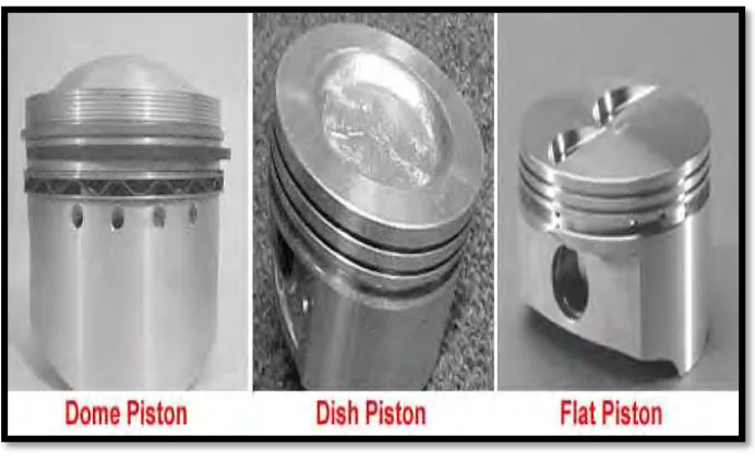
[image:23.595.145.491.245.457.2]In designing an engine, the automotive engineer will create the design with a particular piston head in mind. The piston head must be able to work in accordance with the rest of the piston assembly, as well as with the structure of the combustion chamber and the valve train assembly because they all work together in obtaining the engineer’s goals for engine output and performance. Different piston heads are used to accommodate variations in the combustion chamber and valve train designs. Variations in piston head shapes can also be used to change the compression ratio. The top of the piston may be flat, concave, dome shaped, or recessed.
Figure 2.3: Piston Head Design
2.2.2 Design The Piston of Internal Combustion Engine
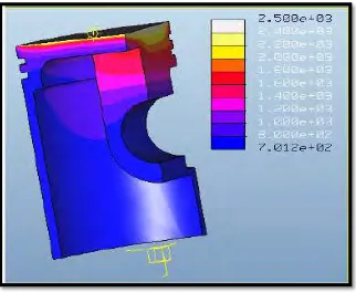
When Pistons are operating, they directly touch the high temperature gas and their transient temperature can reach more than 2500K and generates the 18KW power. The piston is heated seriously and its heat transfer coefficient is 167 w/m ° C and its heat dissipation condition is poor, so the piston temperature can reach 600 ~ 700 K approximately and the temperature distributes unevenly. On the basis of these conditions, we will make thermal analysis for the piston.
8
[image:24.595.175.497.349.614.2]appears the top surface of the piston. The temperature of piston pin changes between 700K and 800K. The temperature of the first ring groove is the important evaluation index of thermal load of the piston and its temperature is between 1300 K and 1500K. The highest temperature differs by 1800 K from the minimum temperature, which will make piston cause larger thermal stress and thermal damage. From the diagram, we can find the piston temperature is gradient descent along the piston axis direction from up to down, but the temperature change of piston skirt is lesser. The diagram indicates that thermal deformation of the piston is bigger from bottom to top and heat distortion of the bottom is minimized. These findings are consistent with domestic researcher's results. In very high temperature Nox will produce, so in designing piston thermal tests is important because we can determine each material or design can produce lower heat or absorb heat and reduced it.
Figure 2.4: Piston Temperature Distribution
2.2.3 Squish Piston