Commission o f t h e European Communit
ies
ear scienc
and technology
The Community's
research and development programme
M s
u<j.b
Commission
of
the
European
Communities
$
C I
*.']&
w
iesäfe
*W< ^ ^ F ' '¿saÇ'" ' ■**V¿ ¥í* **%£»* èfe '^Sw**
The
Community's
research
and
development
programme
on
decommissioning
of
nuclear
installations
Second
annual
progress
report
(year
1986)
Directorate-General
Science,
Research
and
Development
1 ^
v,n°i
IP1987
PAR
r y E Ü H
11112
EN
N.C./EUR
Published by the
COMMISSION OF THE EUROPEAN COMMUNITIES Directorate-General
Telecommunications, Information Industries and Innovation Bâtiment Jean Monnet
LUXEMBOURG
LEGAL NOTICE
Neither the Commission of the European Communities nor any person acting on behalf of the Commission is responsible for the use which might be made of the
following information
Cataloguing data can be found at the end of this publication
Luxembourg: Office for Official Publications of the European Communities, 1987
ISBN 92-825-7385-0 Catalogue number: CD-NA-11112-EN-C
© ECSC-EEC-EAEC, Brussels • Luxembourg, 1987
FOREWORD
This is the second Annual Progress Report of the European Communi-ty's 1984-88 programme of research on the decommissioning of nuclear installations. Tt covers the year 1986 and follows the 1985 Report /l/.
The Council of the European Communities adopted the programme in
January 1984 111, considering: "Certain parts of nuclear installations
inevitably become radioactive during operation; it is therefore essential to find effective solutions which are capable of ensuring the safety and protection of both mankind and the environment against the potential hazards involved in the decommissioning of these installations".
Also, the Council recognized that the 1979-83 programme of research on the decommissioning of nuclear power plants, of which the current pro-gramme is a follow-up, "has yielded positive results and opened up encouraging prospects". The main publications relating to the results of this first programme are listed in Annex I.
The 1984-88 programme has the following contents:
A. Research and development projects concerning the following subjects: Project N° 1: Long-term integrity of building and systems;
Project N° 2: Decontamination for decommissioning purposes; Project N° 3: Dismantling techniques;
Project N° 4: Treatment of specific waste materials: steel, concrete and graphite;
Project N° 5: Large containers for radioactive waste produced in the dismantling of nuclear installations;
Project N° 6: Estimation of the quantities of radioactive wastes arising from the decommissioning of nuclear installa-tions in the Community;
Project N° 7: Influence of installation design features on decommis-sioning.
B. Identification of guiding principles, namely:
- certain guiding principles in the design and operation of nuclear installations with a view to simplifying their subsequent decommis-sioning,
- guiding principles in the decommissioning of nuclear installations which could form the initial elements of a Community policv in this field.
C. Testing of new techniques under real conditions, within the framework of large-scale decommissioning operations undertaken in Member States.
The research is carried out by public organisations and private firms in the Community under cost-sharing contracts with the Commission of the European Communities. The Commission budget planned for this
five-year programme amounts to 12.1 million ECU.
The Commission is responsible for managing the programme and is assisted in this task by the Management and Coordination Advisory Commit-tee "Nuclear fission energy - Fuel cycle/processing and storage of waste"
(see Annex II).
The present report describes the objectives, scope and work program-me of each research contract concluded, as well as the progress of work achieved and the results obtained in 1986.
For each contract, the Paragraph "C. Progress of Work and Obtained Results" has been prepared by the contractor, under the responsibility of the Project Leader. The Commission wishes to express its gratitude to all scientists of the contractors who have contributed to this report.
The Commission staff having edited the report are: E. Skupinski, R. Risei and K. Pflugrad.
B. Huber
Head of the Programme
References
/ l / " T h e Community's research and development programme on decommission-ing of nuclear installations. First annual progress report (vear 1985)". EUR 10740, 1986.
HI Council Decision of 31 January 1984 adopting a research programme concerning the decommissioning of nuclear installations. OJ N° L 36, 8.2.1984, p. 23.
CONTENTS
Page
1. PROJECT N° 1: LONG-TERM INTEGRITY OF BUILDINGS AND SYSTEMS 1 1.1. Long-term stability and leak tightness of reactor
containments 2
2. PROJECT N° 2: DECONTAMINATION FOR DECOMMISSIONING PURPOSES 7 2.1. Complete decontamination of a primary steam piping of the
Lingen BWR 8 2.2. Aggressive chemical decontamination tests on valves from the
Garigliano BWR 10 2.3. Decontamination using chemical gels, electrolytical swab and
jet, abrasives 16 2.4. Development of an easy-to-process electrolyte for
decontami-nation by electropolishing 19 2.5. Optimization of filtering systems for various concrete
decontamination techniques 23 2.6. Economic comparison of decontamination and direct melting
with a view to recycling of scrap 28 2.7. Remote electrochemical decontamination for hot cell
applications 30 2.8. Decontamination with pasty pickling agents forming a
strippable foil 36 2.9. Rack-torch unit for remote decontamination of concrete 40
2.10. Feasibility of concrete decontamination using a
plasma-augmented burner 41
3. PROJECT N° 3 : DISMANTLING TECHNIQUES 42 3.1. Ventilation and filtration techniques for thermal cutting
operations 43 3.2. Prefiltering devices for gaseous effluents from dismantling
operations 50 3.3. Dross and ultrafine particulate formation in underwater
plasma-arc cutting 57 3.4. In-situ arc-saw cutting of heat exchanger tubes and of pipes
from the inside 63 3.5. Electrochemical technique for the segmenting of activated
steel components 69 3.6. Explosive techniques for the dismantling of biological
shield structures , 74 3.7. Explosive techniques for dismantling of activated concrete
structures 80 3.8. Prototype system for remote laser cutting of radioactive
structures 85 3.9. Investigations of applications of laser cutting in
decommissioning 92 3.10. Spreading and filtering of radioactive by-products of
under-water segmenting 96 3.11. Development of a prototype system for remote underwater
plasma-arc cutting 101 3.12. Remote measuring and control systems for underwater cutting
of radioactive components 106 3.13. Removal of concrete layers from biological shields by
microwaves Ill
3.IA. Adaptation of an existing air-tight and modular workshop
for remote operation 115
4. PROJECT N° 4: TREATMENT OF SPECIFIC WASTE MATERIALS: STEEL,
CONCRETE AND GRAPHITE 121 4.1. MeIting/refining of contaminated steel scrap from
decommissioning 122 4.2. Melting of radioactive metal scrap from nuclear
installations 124 4.3. Separation of stainless steel constituents using transport
in the vapour phase 129 4.4. Immobilisation of contamination of large waste units by
polymer coating 135 4.5. Investigations into the melting of radioactive metal waste
in a controlled area 137 4.6. Behaviour of actinides and other radionuclides that are
difficult to measure, in melting of steel 139 4.7. Conditioning and disposal of radioactive graphite bricks
from reactor decommissioning 140
5. PROJECT N° 5: LARGE TRANSPORT CONTAINERS FOR RADIOACTIVE WASTE
PRODUCED IN THE DISMANTLING OF NUCLEAR INSTALLATIONS 141 5.1. Design and evaluation of large containers for reactor
decommissioning waste 142 5.2. Large waste containers made of fibre-reinforced cement 146
5.3. Large waste containers cast of low-level radioactive metal
scrap 149
6. PROJECT N° 6: ESTIMATION OF THE OUANTITIES OF RADIOACTIVE WASTE ARISING FROM THE DECOMMISSIONING OF NUCLEAR INSTALLATIONS IN THE
COMMUNITY 154 6.1. The assessment of low-level contamination from
gamma-emit-ting radionuclides 155 6.2. Development of methods to establish the curie content of
radioactive waste from decommissioning 159 6.3. Systems for contamination measurements on curved surfaces...160
6.4. Optimisation of measurement techniques for very low-level
radioactive material 162 6.5. Monitoring gamma radioactivity over large land areas using
portable equipment 164 6.6. Radioactive wastes arising from the dismantling of a
commercial Fast Breeder Reactor 166 6.7. Radiological evaluation of releasing very low-level
radioactive copper and aluminium 167
7. PROJECT N° 7: INFLUENCE OF NUCLEAR INSTALLATION DESIGN FEATURES ON
DECOMMISSIONING 169 7.1. Decontamination and remote dismantling tests in the ITREC
reprocessing pilot plant 170 7.2. Testing of cobalt-free valve seatings using a special test
loop 175 7.3. In-situ sealing of concrete surface by organic impregnation
and polymerisation 179 7.4. Influence of design features on decommissioning of a large
Fast Breeder Reactor 183
-8. SECTION C: TESTING CF NEW TECHNIQUES UNPEP PEAL CONDITIONS 184 8.1. Dismantling and decontamination of a feedwater preheater
tube bundle of Garigliaro BWR 185 8.2. Conditioning, transport and dismantling of very large
plutonium glove-boxes 191 8.3. Large-scale application of segmenting and decontamination
techniques 196 8.4. Development of techniques to dispose of the Vindscale AGR
heat exchangers 203 8.5. Pilot decommissioning of a mixed-oxide fuel fabrication
facility 210 8.6. Testing of new techniaues in decommissioning of a fuel
(U, Th) fabrication plant 217 8.7. Decontamination and dismantling of the PTVER prototype
vitrification facility 223 8.8. Dismantling, partly in-situ, of a glove-box structure of a
mixed-oxide fuel plant 229 8.9. Melting of radioactive metal scrap from the KRB-A plant ....235
8.10. Volume and plutonium inventories before and after
disman-tling of a mixed-oxide fuel plant 237 8.11. Decontamination, before dismantling, of the primary coolant
system of the RAPSODIE FBR 242 8.12. Automated measuring system for waste from dismantling of
the KKN plant, to be released 248
X X
X
ANNEX I LIST OF PUBLICATIONS RELATING TO THE RESULTS OF THE 1979-83 PROGRAMME ON THE DECOMMISSIONING OF NUCLEAR
POWER PLANTS 254
ANNEX II MEMBERS OF THE MANAGEMENT AND COORDINATION ADVISORY
COMMITTEE "NUCLEAR FISSION ENERGY - FUEL CYCLE/PROCESSING
AND STORAGF OF WASTE" 257
1. PROJECT N°l:
LONG-TERM INTEGRITY OF BUILDINGS AND SYSTEMS
A. Objective
It has been proposed that the dismantling of nuclear installations be delayed for periods ranging from several decades to about a hundred years. Thereupon, the radioactivity having largely died away, dismantling would be easier and the radiation exposure of the dismantling personnel would be less. The objective of this project is to determine the measures required for maintaining shut-down plants in a safe condition and to assess the radiological consequences and costs.
P. Research performed under the 1979-83 programme
The work performed under the previous programme relates mainly to the following aspects:
- mode and pace of degradation of various materials as they exist in nuclear power plants;
- measures for maintaining plants in a safe condition and for keeping the necessary ancillary systems operable;
- monitoring and inspection procedures ;
- radiological consequences and costs of maintaining the plants.
C. 1984-88 programme
The work performed under the first five-year programme should be comple-mented by further tests and the study of control methods relating to the aging of relevant plant materials and by exploitation of additional experience with shut-down nuclear installations.
D. Programme implementation
1.1. Long-term Stability and Leak Tightness of Peactor Containments
Contractor: Zerna, Schnellenbach und Partner GmbH, Bochum, Germany. Contract N": FI1D-0031
Working Period: April 1986 - June 1988 Project Leader: R. Oberpichler
A. Objectives and Scope
The objective of this research is to study the long-term performance of structures comprising nuclear power plants. The time period of inte-rest for this study is 140 years, account being taken of maximum periods of 40 years for operation and 100 years of storage. Particular attention will be given to those parts of the plant for which leak tightness and structural integrity are required, both during operation and for long periods after final shutdown.
The specific aim of this research is to investigate the behaviour of complex composite structures, taking as a basis the long-term behaviour of materials. The possible susceptibility to long-term damage will also be assessed, and the areas most prone to such damage will be identified. Further consideration will be given to the possible interaction between sealing steel components (steel containments, steel liners) and load bearing concrete structures.
This building survey will be carried out on structural elements of actual PWR stations (e.g. Emsland-Lingen) and BWR stations (e.g. Gundrem-mingen B and C). Consideration will be given to the validity of the
investigations for relevant structures of other commercial nuclear power plants in the European Community. This investigation will include the
shut-down BWR station of Garigliano in Italy.
B. Work Programme
B.1. Investigation on reinforced concrete and prestressed concrete structures.
B.l.l. Selection of structural elements considered important with regard to the integrity of long-term containment.
B.1.2. Literature study on material behaviour covering long-term proper-ties.
B.1.3. Analysis of the long-term behaviour of the selected structural elements.
B.2. Investigation of steel containments
B.2.1. Selection of elements susceptible to damage, in particular plastic sealings with concrete and steel.
B.2.2. Assessment of damage (state of material, types of corrosion, formation of condensed moisture, permeability of the concrete, etc.)
B.2.3. Optimization of ultrasonic testing techniques (angular sound, weakening, creep wave, etc.) and application of the selected techniques to decommissioned Niederaichbach and Gundremmingen I nuclear power plants.
C. Progress of work and obtained results
Summary
During the f i r s t reporting period the following parts of the work
programme have been worked on:
- specification of concrete structural elements which are considered
important to the long-term s t a b i l i t y ( B . l . l ) ;
- literature studies on long-term material behaviour concerning the
pro-perties of concrete, reinforcing steel and prestressing steel (B.1.2);
- studies on type of corrosion mechanisms, corrosion areas and
corro-sion rates concerning the steel containments (B.2.1, B.2.2).
Progress and results
T.
Specification of the main concrete structural elements ( B . l . l . )
Aim of this working step was getting knowledge about the function
of the structural elements of the referred power plants concerning their
bearing behaviour and hence about their importance due to the long-term
s t a b i l i t y of the entire reactor buildings. Those structural elements
are named and proposed for analysing in the following working period.
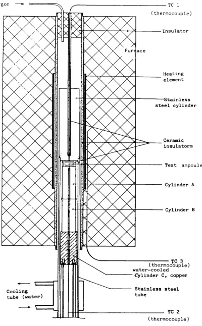
In Fig. 1 a section of a PWR-station and in Fig. 2 a section of a
BWR-station are shown. The hatched parts are mainly responsible for the
long-term s t a b i l i t y of the reactor buildings.
Especially the primary and secondary containments including the
suppor-ting structures, the biological shield and some special wall elements
are proposed for investigations in working step B.1.3.
2. Literature studies on material behaviour of concrete and
reinforcing steel (B.1.2.)
The literature studies on material behaviour are devided into three
parts:
- properties of concrete
- properties of reinforcing and prestressing steel and
- properties of the composite material consisting of steel and
con-crete .
Several conclusions can be given from the literature studies for later
analysing the main structural elements of a reactor building:
- The strength of concrete is not expected to decrease during the time
of 100 years after decommissioning.
- The carbonation depth is not expected to exceed about 20 mm on an
ave-rage within the regarded period of time. Only under worst
environmen-tal and concrete quality conditions the carbonation depth has reached
about 70 mm.
- According to the kind of aggression concrete corrosion is devided into
three areas:
- physical
- physical-chemical
- chemical and
- microbiological.
- The chemical corrosion of concrete requires aggressive agents which
are not l i k e l y to occur in a decommissioned nuclear power plant.
- Deteriorations of concrete by radiation require high values of fluence
and a high y-radiation dose which are not expected in the period after
decommissioning.
- As the most observed corrosion type the electrochemical corrosion of
reinforcing steel may only occur in those parts of the concrete
struc-tures where the steel depassi vates in consequence of concrete
carbo-nati on or high concentration of chloride ions.
- The environmental conditions have to be taken into consideration very
carefully, because in particular the grade of humidity, its frequent
changings during lifetime, the concentration of carbon dioxide or
chloride, the pollution of air and water by sour agents and the
tempe-rature are of great influence on the durability of concrete and steel.
The durability depends mainly on the grade of carbonation of the concrete
effecting the loss of its alcaline properties, on concrete corrosion
and on steel corrosion of the embedded steel.
Although the durability of concrete is known by tests for a period
less than about 50 years the development of the material properties for
a period of about 100, respectively 140 years, can be estimated with
some approach to accuracy. Nevertheless methods of monitoring the actual
state of the composite elements for each time are to be proposed in the
following working step to provide security for unexpected environmental
conditions.
3. Investigations on steel containments (B.2.1, B.2.2.)
During the third research project concerning the steel containments
an attempt was made to look into the following:
- type of corrosion mechanisms assumed,
- areas of the container requiring special attention,
- observation of the corrosion rates to be assumed.
First conclusions can be drawn from these results for carrying out
re-current tests.
Recently, elastic plastics have mainly been used to seal steel
com-ponents from structures of reinforced concrete.
The aim of these tests is to create a basis for sensible
extrapo-lation of the long-term behaviour of sealed joint constructions of this
kind, taking account of the conditions in which they are used.
+54,4 m
%
± 0,0 m
v
- 6,0 m
VAWAVAVUJA inner rooms
UJB surrounding rooms
U-JE steam and feed water valve compartment
1 steel reactor pressure vessel
2 biological shield
3 calotte shell
4 circle wall
5 foundation plate
6 reactor building crane
7 steel containment (primary containment)
8 reinforced concrete containment
(secondary containment)
Fiq. 1
Section of the PWR-Station
v +60,4 m
- 9
1 steel reactor pressure vessel 2 bi ologi c?1 shield
3 'irestressec; concrete containment (primary containi'icnt) 4 condensation room
5 steel liner
6 fuel assemblies deposit basin 7 surrounding rooms
8 reactor building crane
9 reinforced concrete containment (secondary containment)
10 pressure room
Fi_g._2 Section of the_ BWP-Station
2. PROJECT N°2:
DECONTAMINATION FOR DECOMMISSIONING PURPOSES A. Objective
The objective of this project is to develop and assess techniques for decontaminating surfaces of components and structures of nuclear instal-lations that are past use. The main purpose of decontamination would be reduction of the occupational radiation exposure during dismantling of the contaminated item and/or reduction of the volume of radioactive waste.
B. Research performed under the 1979-83 programme
The following decontamination techniques have been developed and asses-sed:
- techniques based on the use of chemically aggressive decontaminants in liquid and gel-like form;
- electrochemical techniques;
- hydromechanical techniques (high-pressure water lance, erosion by cavitation);
- decontamination of concrete walls by flame spraying. Other activities were:
- investigation of the characteristics and distribution of contamination in nuclear power plants that are past use;
- economic assessment of decontamination for unrestricted release;
- collection of information on the particular decontamination problems posed by accidental contamination, as in the case of the TMI-2 nuclear power plant.
C. 1984-88 programme
Selected aggressive decontamination methods should be further developed with a view to their industrial application. Increased effort should be paid to the conditioning of spent decontaminants, where suitable techni-ques do not yet exist, and to the reduction of secondary waste arisings. Physical methods that limit the production of liquid effluents might be considered.
An important new topic of the second programme would be the decontamina-tion of hot cells and equipment contaminated with plutonium and other transuranics for purposes of the decommissioning of fuel-cycle installa-tions. The specific features of such installations (chemical nature of the liquids used during their operation, dimensions of the components, etc.) would be taken into account.
D. Programme implementation
2.1. Complete Decontamination of a Primary Steam Piping of the Lingen BWR
Contractor: Kernkraftwerk Lingen GmbH, Lingen, Germany Contract Ñ°: FIlD-0001
Working Period; January 1985 - March 1986 Project Leader: W. Ahlfänger
A. Objectives and Scope
A foregoing research contract (DE-B-004-D), aimed at the investiga-tion of the composiinvestiga-tion of contaminainvestiga-tion layers and of the effectiveness of possible decontamination procedures of primary circuit steam lines, was concluded by following main results:
- the surface contamination is to an extent of 99% of oxide composition, the remainder is located at a penetration depth of up to 90 um in the base material. For a successful decontamination, it is necessary to
dissolve, besides the oxide layer deposited on the surface, also a small layer of the base material;
- the best way of decontamination (using solutions with less than 2% concentration) is to strip the deposited oxide layer by a LOMI react-ive and a part of the base material by a mixture of hydrochloric and nitric acid.
These results have been obtained by laboratory-scale tests on representative samples.
The obiective of this research contract is to demonstrate that thp above decontamination procedure is also appropriate for a large-scflle application to a steam line of the Lingen Nuclear Power Station.
B. Work Programme
B.1. Manufacturing of the decontamination rig comprising the sample steam pipe and all needed components for decontamination.
B.2. Preliminary laboratory decontamination tests of representative samples including determination of the composition and activity level of the contaminated layer.
B.3. Main test programme using the decontamination rig.
B.4. Assessment on optimal treatment of the generated radioactive secon-dary waste.
C. Progress of Work and Obtained Results Summary
This work has been completed by a study of application of the procedure to a large pressurised water reactor and by drawing the conclu-sions.
Progress and Results
In the 1985 annual progress report, the complete decontamination of a primary steam line has been described. The conclusions drawn from this work are presented hereafter.
As was shown by the examination results, the pipe could be deconta-minated below the tolerance limits of the German Radiation Protection Regulation. Following special problems arose during the tests:
- A strong pitting attack during the acid treatment with a too high content of FeCl,.
- The metal oxides precipitated during the acid treatment were only partially removed by the subsequent steps, so that considerable activi-ty quantities were carried on into the subsequent treatment cycle.
Concerning the application of the procedure to a 1300 MW pressurised water reactor, the decontamination of the primary circuit has been
considered as an example. At that, the decontamination course has been modified in such a way that the mentioned problems should no longer
occur.
The special advantage of the procedure can be seen in its possibili-ty to be used independently of the radiation level of the system. Works needing much time concerning the highly contaminated plant parts, which
lead to large additional radiation exposure of the personnel, are not necessary if the course of the procedure is carefully planned. By this, one gets the freedom of decision to decontaminate a plant immediately after the shutdown or only later when a part of the radioactivity has decayed. As the main part of the activity consists of cobalt-60, one had to accept a waiting time of 35 years for example to obtain a decay factor of 100.
The serious disadvantage of the process consists in the application of large quantities of chemical solutions. A certain compensation is, however, given by the facts that the concentrations of the chemical solutions are relatively low and that only the treatment solutions are to be evaporated. The water used for the subsequent rinsing can be processed
through the primary purification plant.
2.2. Aggressive Chemical Decontamination Tests on Valves from the Gari-gliano BWR
Contractor: Ente Nazionale per l'Energia Elettrica, Roma, Italy Contract N°: FI1D-0002
Working Period : January 1985 - December 1986 Project Leader: F. Pregani
A. Objectives and Scope
The aggressive chemical decontamination methods, whose effectiveness has been proved both in many laboratory tests and in pre-industrial applications, appear to need further investigations regarding both the decontamination of complex systems, such as valves, and spent decontami-nant treatment in view of the limitation of the secondary wastes
aris-ings.
The scope of the research is both to check the effectiveness of hard chemical decontamination on used components, such as small valves, and to search and develop a suitable and safe procedure to treat spent solu-tions, arising from aggressive chemical decontamination.
The advantages of this research are the possible demonstration of the decontamination effectiveness on complex components and the minimiza-tion of the total wastes produced.
This proposed research will be carried out in collaboration with CISE in the framework of a specific multi-annual agreement already in force. The experiments will be performed in DECO laboratory at Ispra, JRC.
Regarding the application of chitosan, specific agreements with the University of Ancona have already been undertaken.
B. Work Programme
B.1. Aggressive chemical decontamination tests on valves (2-3 inches) of
the primary cooling system of the Garigliano BWR in DECO loop.
B.2. Identification and qualification of a simple procedure to condition the spent decontaminant.
B.3. Neutralization and flocculation tests in order to select and evalu-ate the best neutralizing agent and specific chemical agents, such as chitosan, as supporter in flocculation.
B.4. Cost evaluation of the process and assessment of the possibility of reprocessing and reutili zing of specific agents.
-C. Progress of work and results obtained
Summary
Two more decontamination tests on small valves from the Garigliano-BWR are described. These tests were performed with a preliminary soft chemical decontamination step before the aggressive one.
At the end of the decontamination experiments on valves, the recorded data were treated in order to try to draw some general conclusions and to out-line the lesson learned.
A schema for the decontamination of small and complex components is given. Concerning the waste treatment the neutralization and precipitation tests and the characterization of residual sludges 'are reported.
A general procedure for processing contaminated aggressive solutions from decontamination is presented.
Progress and Results
1. Hard chemical decontamination tests on valves (2-3 inches) of the pri-mary cooling system of the Garigliano BWR in PECO loop (B.l)
After the two decontamination tests carried out in 1985, two more tests on small valves (called No. 3 and 4 respectively) of the primary cooling sys-tem of the Garigliano BWR, were performed in the DECO experimental loop. Taking into account the results of the first two tests, these runs were performed with a soft chemical decontamination step the hard aggressive chemical step. That was scheduled in order to check whether a preliminary softening action can help the following aggressive decontamination, in dead areas in particular. A mixture of citric-oxalic acids was used as soft chemicals.
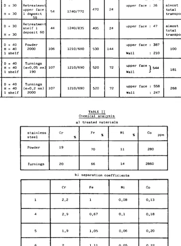
These tests are listed in detail in Tables I and II.
At the end of the runs on the DECO loop the valves were monitored to identify the residual radioactivity trends. Then they were cut off to take specific samples for gamma radiometric measurements.
The results of these tests show that:
- the decontamination effectiveness does not appear to increase with the preliminary soft chemical decontamination step;
- some hot spots remain in the valves whatever the decontamination process; - concerning the effect of the ultrasound step (made in common tanks, in
demineralized water at room temperature) the effectiveness varies largely depending on the nature of the contaminated oxide layer which covers the valve: in valve No. 3 (as in valve No. 1) the oxide layer was loose and the ultrasounds were very effective, while in valve No. 4 (as in valve No. 2) the oxide layer was thick and adherent and the ultrasounds were poorly (or not) effective.
2. Neutralization and flocculation tests to select and evaluate the best neutralizing agent and specific chemical agents, such as chitosan as supporter in flocculation (B.3)
Many batch tests have been performed to establish the experimental ranges of precipitation of Co and Fe in varying the nature of the spent solution
(HF + HNO , HCl + HNO and HCl), the initial concentration of iron and/or cobalt, the kind of neutralization agent, presence of flocculant and so on. The C0-60 radioactivity was measured by an Na-I detector in a shielded box. The metal concentration in the solution was evaluated by a UV spectrofoto-meter and Atomic Absorption.
The tests were performed in graduated 1 litre beakers and in small 50 cc beakers, with a magnetic 200 rpm stirrer.
As a conclusion, spent radwaste solutions in aggressive mineral acids coming from surface decontamination can easily be treated for volume re-duction by means of the simple chemical process of neutralization with NaOH and/or CaO. Improvement of the purification was obtained by adding chitosan to the early radwaste solution. The radioactivity of the treated spent rad solution was less than or around 0.1 Bq/cm .
A characterization of residual sludges arising from neutralization precipi-tation was also performed. The main results are:
- the residual sludges retain more than 90% of water;
- three phases are usually present in the dry residual: hydroxides such as Fe(OH) and so on, salts and particulate oxide matters;
- the radioactivity of course is retained only in the hydroxide and particulate phases.
3. Identification and qualification of a simple procedure to condition the spent decontaminants (B.2)
From the results of the previous task, the following operative schema is proposed for the treatment of aggressive chemical spent decontaminant: - put the waste solution into a proper tank;
- neutralization with sodium hydroxide up to pH 5; - stirring and décantation;
- filtration or separation to eliminate Fe(0H) precipitates which should 3
retain very low radioactivity;
- add some more NaOH with chitosan powder (0.5 g/1) up to pH 7;
- filtration or separation to recover other hydroxide precipitates such as Co(0H)n, etc. which should retain almost the total radioactivity;
- if possible discharge the floating solution;
- if necessary and possible treat the residual sludges further by evapora-tion.
As an alternative after Fe elimination chitosan columns could be used for Co removal. This way has not yet been tested.
4. Cost evaluation of the process and assessment of the possibility of re-processing and reutilizing of specific agents (B.4). Conclusions:
At the conclusion of the experiments on decontamination of small valves from the Garigliano BWR power station, the following considerations can be made and extended to all small components:
- before taking the decision whether to decontaminate for decommissioning purposes, a small and complicated component or parts or not, it is ab-solutely necessary to establish clearly how to measure the residual
radioactivity after treatment;
- whatever the decontamination process may be some hot spots remain in the valve (or components); these hot spots will definitely be greater than 1 Bq/g or 1 Bq/cm (Table III);
- if the decontamination is performed, also in terms of average residual radioactivity it is very difficult to establish "a priori" whether the valve (or component) can be released or not; valves (or components) which are simpler or covered with loose contamination will more probably be totally decontaminated than valves (or components) which are more complex or covered with thick and tenacious contamination.
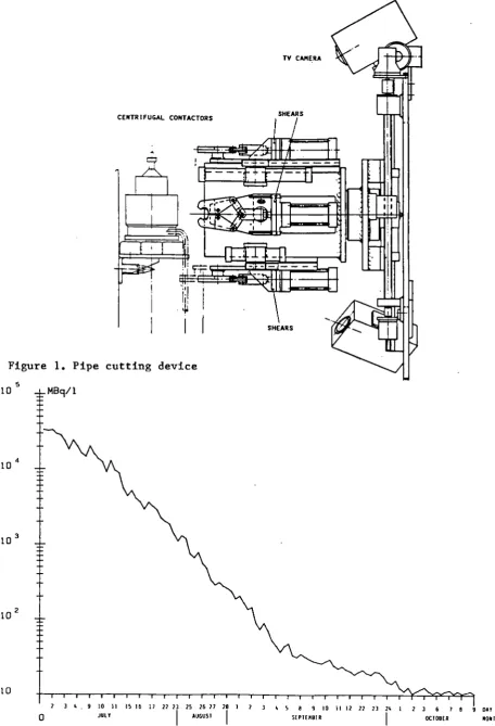
From the analysis of the results and from the above considerations a process diagram can be proposed for the decontamination of small and complex components contaminated by the recirculating coolant in an LWR. The proposed diagram is given in Fig. 1 .
[image:23.595.97.485.422.703.2]Because the results do not show clearly how one might be able to achieve the unrestricted release of materials, a consistent cost evaluation asses-sment has not yet been made. It could be made at the end of the second phase of the research programme in which the use of combined ultrasounds and aggressive chemicals is considered to improve the decontamination ef-fectiveness of the process.
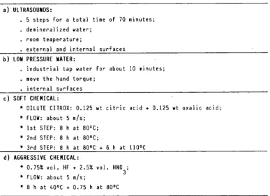
TABLE I - Decontamination steps of valve No. 3 (globe valve, 1 inch)
a) ULTRASOUNDS:
. 5 steps for a total time of 70 minutes; . demineralized water;
. room temperature;
. external and internal surfaces b) LOU PRESSURE HATER:
. industrial tap water for about 10 minutes; . move the hand torque;
. internal surfaces c) SOFT CHEMICAL:
* DILUTE CITROX: 0.125 wt citric acid + 0.125 wt oxalic acid; * FLOW: about 5 m/s;
* 1st STEP * 2nd STEP * 3rd STEP
8 h at 80°C; 8 h at 80°C;
8 h at 80°C + 6 h at 110°C d) AGGRESSIVE CHEMICAL:
* 0.75% vol. HF + 2.5* vol. HNO. * FLOW: about 5 m/s;
* 8 h at 40°C + 0.75 h at 80°C
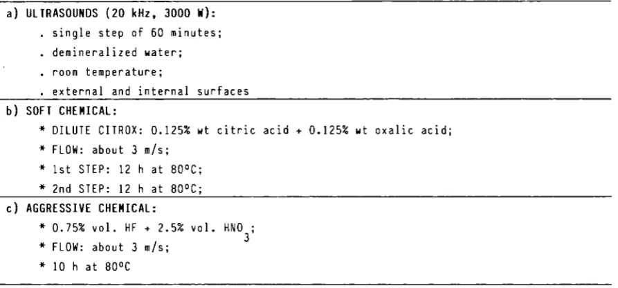
-TABLE II - Decontamination steps of valve No. 4 (y-type valve, 1 1/2 inches) a) ULTRASOUNDS (20 kHz, 3000 W ) :
. single step of 60 minutes; . demineralized water; . room temperature;
. external and internal surfaces
b) SOFT CHEMICAL:
* DILUTE CITROX: 0.125% wt citric acid + 0.125% wt oxalic acid; * FLOW: about 3 m/s;
* 1st STEP: 12 h at 80°C; » 2nd STEP: 12 h at 80°C;
c) AGGRESSIVE CHEMICAL:
* 0.75% vol. HF + 2.5% vol. HNO ; 3 * FLOW: about 3 m/s;
* 10 h at 80°C
TABLE III - Specific residual radioactivity in the decontaminated valves. Valve No. (froi Garigliano BWR Dlant) 1 2 3 4 Decontamination process (*)
US + AC + US + BR
US + AC + US + EL
US + WL + SC + AC
US + SC + AC
Weight the val (kg) 10.5 25.5 10.2 24.5 of ue Estined Surface Inside 12.5 7.0 12.5 7.0 (d» ) Total 21 19 21 19 Specif Height (Bq/g) 0.44 3.41 0.41 2.08
Residual L
ic radioactivity Surface Inside 3.68 124.29 3.36 72.86
(Bq/c.2)
Total
2.19 45.79 2.00 26.84 (*) Decontamination steps: US = ultrasounds in demineralized water;
SC = soft chemical (citric + oxalic acids);
AC = aggressive chemical (hydrofluoric + nitric acid); WL = water pressure (4 kg/cm ) ;
BR = brushing (outside surface); EL = electropolishing.
[image:24.595.78.525.80.288.2]SHALL i COMPLEX COMPONENTS CONTAMINATED BY-RECIRCULATING COOLANT IN LWR
IF POSSIBLE ULTRASOUND IN DEMORALIZED WATER
UNRESTRICTED RELEASE
AGGRESSIVE CHEMICAL DECONTAMINATION HCl, HF, HNO
FINAL RADIOMETRIC CONTROL
KNOWLEGE OF
UNRESTRICTED RELEASE CRITERIA
. LIMITS
. HOW TO MEASURE
PROCESS LIQUID WASTES BY COMMON FILTERING
PROCESS LIQUID WASTES BY NEUTRALIZATION AND PRECIPITATION
NO UNRESTRICTED RELEASE
STORAGE MELTING ETC.
FIGURE 1 - Proposal diagram for decontamination of small and complex components
2.3. Decontamination Using Chemical Gels, Electrolytical Swab and Jet, Abrasives
Contractor: Commissariat à l'Energie Atomique, CEN-Cadarache, France Contract N°: FI1D-0003
Working Period: January 1985 - December 1987 Proiect Leader: F. Josso
A. Objectives and Scope
As part of the dismantling of a nuclear installation, it is neces-sary to dispose of rapid and efficient decontamination procedures (high decontamination factor), which are simple to apply and lead to a low volume of wastes easy to treat.
The aim of this research is to study the following new decontamina-tion techniques with a view to their applicadecontamina-tion in the dismantling of nuclear installations:
- spraying of gels,
- electrolytical swab and jet, - abrasive water blasting.
These technioues are expected to usefully complement the established methods (immersion in chemical bath, electrolytical bath, high-pressure jet) developed in a previous study (Ref.: EUR 10043).
B. Work Programme
B. 1. Optimization of the decontamination processes, i.e. chemical gels, electrolytical swab and jet and abrasive water blasting, on non-radioactive samples of stainless steel, mild steel and aluminium. B.2. Application on contaminated samples from various types of plant
(graphite-gas reactor, PWR, LMFBR, fuel fabrication plant and reprocessing plant).
B.3. Implementation of these techniques with remote control and in the nuclear facilities before dismantling.
B.4. Assessment of quantity of secondary waste and its treatment.
B.5. Cost evaluation and assessment of radiological consequences of each process, including the treatment of secondary waste.
-C. Progress of Work and Obtained Results Summary
The year 1986 was devoted to both an industrial application of gel spraying, and tests for implementation of decontamination techniques with remote control.
The first stage consisted in decontamination of a bituminisation plant and its dismantling. The second stage consisted in preliminary tests on a robot able to operate the three decontamination methods (gels spraying, swab electropolishing, abrasives). These tests have been performed in a cell, and results could be applied to decontamination after dismantling.
Progress and Results
1. Decontamination of bituminisation plant (B.2.)
The objective of this operation was to dismantle a bituminisation plant located in Brittany (BRENNILIS) and to re-build it in CADARACHE.
The main part of the plant (low- and medium-activity cells, evapora-tor platform, tanks, etc.) was decontaminated by gel spraying containing nitric acid (2 to 5 mol/1) , hydrofluoric acid (0.05 to 1.6 mol/1) and oxalic acid (0.08 to 0.25 mol/1). The pipes were decontaminated by circulation of solutions containing the same chemical reagents. The residual contamination was, generally, less than 4 Bq/cm2.
The biological protection was composed of 113 t of lead bricks (55 t non-radioactive and 58 t to be decontaminated). The bricks were deconta-minated in a chemical bath containing nitric acid (7 mol/1). The most
contaminated bricks were pre-decontaminated with a gel containing nitric acid (5 mol/1) and oxalic acid (0.04 mol/1). After decontamination, 56 t had a residual activity less than 3.7 Bq/cm2, and 2 t a residual activity
between 3.7 and 37 Bq/cm2. These 2 t were melted.
The decontaminated parts are as follows:
- 150 to 200 m2 of stainless steel surfaces by gel spraying;
- 90 m2 of stainless steel and concrete surfaces and 50 m of pipes by
chemical solutions;
- 400 m2 of lead brick by chemical bath.
TABLE I
Residual activity and destination of the materials of the bituminisation plant after decontamination
Components
Carbon and stainless steel - non-decontaminated - decontaminated Lead bricks - non-decontaminated - decontaminated - decontaminated insufficiently Weight (t) 15 45 55 56 2 Volume (m3)
40 98
Residual activity A (Bq/cm2)
non-radioactive A < 3.7
non-radioactive A < 3.7 3.7 < A < 3.7
Destination reuse reuse reuse reuse melting
-The total amount of secondary liquid wastes produced after neutralisation
was 7.2 m3 (75% coming from decontamination in chemical bath):
- the first 1.6 m3 was embedded in bitumen,
- the remaining liquid wastes was composed of
. 150 kg sludges - lead oxides - (dose rate - 5 mRad/h);
. 5.4 m3 low-level activity liquid wastes (activity of Cs-134 and
Cs-137 < 370 Bq/1 and activity of Co-60 = 1850 Bq/1).
Following solid wastes were produced by decontamination and installa-tion dismantling:
- low-level activity: 17 m3 compressible solid wastes and 12 m3
non-com-pressible wastes.
- medium-level activity: 425 1 non-compressible wastes and 600 1 decon-tamination effluents (3 drums with bitumen).
The decontaminated parts of the installation, about 140 m3 (60 t),
will be reused for construction of another bituminisation plant. The decommissioning of this installation involved 6.5 man-rem.
2. Decontamination with remote control (B.3.)
The objective of this study is the capacity of using all three decontamination methods with remote control.
An industrial robot was chosen. Tests were performed with this robot implanted in a cell where decontamination has to be operated.
The first stage consisted in evaluating the capabilities of the robot for following the surface of the part to be decontaminated.
2.1. Standard use of the robot
First tests have been performed for following surfaces, using the robot without adding any additional device.
In this case, the robot either is used as a manipulator by means of a manual control unit, or is programmed by means of a terminal. For this application, the parts to be decontaminated are classified into two categories: flat and cylindrical parts.
At the beginning, the operator, by means of the manual control unit, moves the arm of the robot to three points which define either a plane or a cylinder. Afterwards, the robot arm is moved by the program and runs over the part surface. The step between two lines and the distance between the tool and the part to be decontaminated can be entered in the program before running it.
In this procedure, the distance between tool and part to be deconta-minated is not constant when the part differs from a plane or a cylinder.
Further studies will consist in evaluating the precision which is required according to each decontamination method.
2.2. Use of sensors
Other tests were performed, using sensors added to the previous programs.
In this case, the operator chooses either the flat parts program or the cylindrical parts one, according to piece geometry. The operator defines, with manual control unit, the 3 points. Afterwards, the robot runs over a surface corresponding to part geometry. The distance between tool and piece is now maintained constant by the sensor.
In the next few months, the three decontamination methods will be tried with this robot.
2.4. Development of an Easy-to-process Electrolyte for Decontamination by Electropolishing
Contractor: Kraftanlagen Aktiengesellschaft, Heidelberg, Germany Contract N°; FI1D-0004
Working Period: November 1984 - April 1987 Project Leader: A. Steringer
A. Objectives and Scope
Electropolishing has become an approved and suitable decontamination process achieving high decontamination factors. However, the spent electrolyte is hard to process and convert into a waste form suitable for disposal. For example, in order to solidify phosphoric acid at a concen-tration above 60% in cement, it must be neutralised and heavily diluted. As a result, the waste volume for disposal is much higher than the initial electrolyte volume.
The aim and objective of this research is to find an easy-to-process electrolyte with high decontamination factors, suitable for disposal, which would give a much wider range of application to electropolishing as a decontamination process. This means that it should be possible to condition the spent electrolyte in simple process steps, such as filtra-tion, sedimentation and thermal decomposifiltra-tion, to produce a waste form that is easy to fix in cement.
The specified requirements with a view to easy processing of the electrolyte are fulfilled by a number of organic acids. In 1983, the contractor carried out various tests and experiments on organic acids. Whereas decontamination factors were satisfactory, unsatisfactory results were obtained for the electropolishing time, the service life and thermal stability of the electrolyte, current density etc. These process parame-ters must be optimised. This work will be carried out in collaboration with TEAM, Italy.
B. Work Programme
B.1. Literature survey for identification of the available information on already existing experience.
B.2. Selection of electrolytes other than phosphoric acid, promising easier conditioning and waste disposal.
B.3. Test series on contaminated and non-contaminated samples in order to optimise the electrolytes with regard to decontamination efficiency (effect of chemical additives, of modifying process parameters,...). B.4. Optimisation of the process to minimise the final waste volume. B.5. Development of procedures to extend the lifetime of electrolytes, in
particular by continuous filtration.
B.6. Processing of selected electrolytes (sediment elimination, salt precipitation, solidification of sludges, volume reduction of the residual liquid, solidification of electrolyte residues).
B.7. Investigations about "on-the-job-safety": chemical aggressiveness, formation of toxic products, explosion hazards, etc.
C. Progress of work and obtained results Summary
The work carried out during the reporting period consisted of following points:
- Development of a third electrolyte on the basis of acetylacetone; - Influence of the chemical, electrochemical and mechanical removal on
the calculation of the current yield;
- Manufacturing of a 400 A pilot plant to check the laboratory results. Progress and results
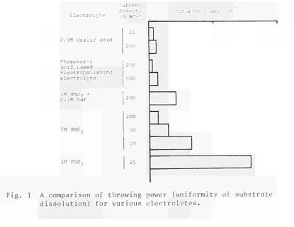
1. Description of the Electro-Descaling Process (B.3.)
In addition to the already developed electrolytes (formic acid, oxalic acid), a third electrolyte was developed on the basis of acetyl-acetone 5% with potassium bromide (KBr). The electrolyte has a better anode-current-yield (ACY) than oxalic acid. The generated acetylacetona-tes are less soluble than the oxalaacetylacetona-tes. The sediment is more coarse-crystalline. A comparison of the results is shown in Figure 1. The test results with acetylacetone are shown in Figure 2. The acetylacetone is consumed and metal salts are produced in the course of the electrochemi-cal deselectrochemi-caling process (ECD). It is necessary to regularly make up for the required acid percentage. The "admixed" KBr is not used up, and its concentration in the electrolyte solution remains unchanged. The electro-lyte was tested on carbon steel samples and stainless steel samples.
The surfaces on the stainless steel samples were very rough after the ECD process (R > 30um; R > 10 u m ) . This fact pointed to a selective dissolution of single alloying stainless steel components. However, an analysis of the electrolyte showed metal contents corresponding exactly to the composition of the stainless steel. This proves that the dissolu-tion has not been selective.
As a result of the solubility coefficient of the produced metal salts, the concentration Increases up to a maximum value of 5 g/1. The above specified concentrations signify the saturation limits for the metal salt/electrolyte solution. After having reached this saturation limit (which, in the case of the phosphoric/sulphuric acid electrolyte used so far, is of about 130 g / 1 ) , the metal salts settle out in the following form: Fe(acac)„, Fe(acac)„, Co(acac)_, Ni(acac)„.
The metal salts in the electrolyte settle out in bivalent (70%) and trivalent (30%) form. In the case of stainless steel, all alloying constituents are in the electrolyte solution; cobalt and nickel are specified above as examples.
As a result of the settling out of the metal salts after having reached the solubility limits, it is ensured that radiologically balanced conditions are met. Radioactive metal ions are enriched in the electro-lyte until the solubility limit is reached. If further radioactive metal ions are produced during the decontamination, they settle out and the resulting sediment can be removed. The maximum activity of the electro-lyte solution is thus determined by the solubility of the salt and metal elements. In the case of acetylacetone, the service life seems to be almost unlimited as regards radiological aspects. If, as a result of fouling (oil e t c . ) , the disposal of the electrolyte as waste is required after a certain time, it is recommended to electrolytically use up the residual acid, using inactive iron for the electrochemical dissolution. The spent electrolyte to be disposed of is composed of 1 wt% acetylace-tone and 5 g/1 acetyl acetonates.
-According to estimates based on activity analyses of the phospho-ric/sulphuric acid electrolyte, the activity expected for acetylacetone
is 10 Bq/m3. This activity value may further be reduced by precipitation
processes.
For the produced metal salts and metal elements, the activity value is expected to be
10 - 10 Bq/m3, as a maximum.
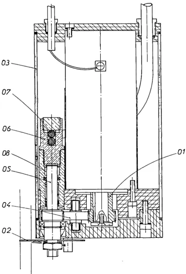
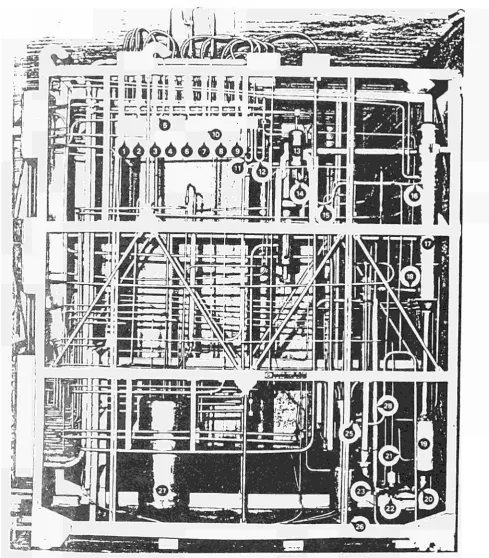
2. Manufacturing of a 400 A pilot plant (B.3.)
For tests on contaminated samples, a 400 A pilot plant (Figure 3) was manufactured. This plant, which is optimised for the electro-descal-ing process, is made of stainless steel and is equipped with a coolant jacket to cool the electrolyte.
The electrolyte tank has a 52 liter volume. The electrolyte heats up at the electrodes. In order to obtain a good thermodynamics, the electro-lyte is circulated with a centrifugal pump (V = 90 1/min).
The required direct current supplies a 400 A air-cooled rectifier which enables the electrochemical treatment of larger surfaces of real samples.
The settled-out metal salts, formed during the electrochemical descaling process, are continuously separated from the electrolyte inside the settling tank. Therefore, the radiological lifetime of the electro-lyte is theoretically unlimited.
CURRENT DENSITY 1=20 A/dm2
ANODE CURRENT YIELD
H j P 0 , , / H2S 0t OXALIC ACID OXALIC AC 10
K Br OXALIC ACID KCl ACETYL ACETON FORMIC ACID KBr KBr FORMIC ACID
ELECTROLYTES
Figure 1 : Comparison of electrolytes
Stainless steel samples
Anode current yield
17.1
10015 0
-Current d e n s i t
T = 16 A/dmí
I
C D I = 20 A/dm
Electrolyses Duration = 0.5 h Temperature = 323 K
A
35
EKES
A
I
A
IS
•— pH = 5 — ' L-pH = 7—J ^— pH = 9—J
Figure 2: Test results with 5% acetylacetone solution with KBr (0.5 M)
— EIEKTR0LYTE
SEDIMENT
CIRCULATION PUMP
Figure 3: The pilot plant 400 A
-2.5. Optimization of Filtering Systems for Various Concrete Decontamina-tion Techniques
Contractor: Salzgitter AG, Salzgitter, Germany Contract N": FI1D-0005
Working Period: January 1985 - June 1987 Project Leader: W. Ebeling
A. Objectives and Scope
The effectiveness of mechanical and thermal methods for the deconta-mination of concrete surfaces has already been demonstrated. However, the
collection and conditioning of the important amount of generated dust, aerosols and toxic gases needs further development.
As concerns the filtration during thermal decontamination, multi-stage storing filters, as currently used in the nuclear industry, have shown adequate efficiency, but their limited storage capacity precludes an economic operation. Concerning the effectiveness of filtration systems for mechanical decontamination, no extensive investigations have been undertaken, so far.
The aim of this research programme is to investigate various filter systems, such as storing filters, regenerative mechanical filters, electrostatic' filters, concerning their separation efficiency, their storage capacity and service life, including an analysis of the amount and size distribution of dust available at each filtering stage. The experiments will use dust generated by the above decontamination methods on non-radioactive concrete samples.
Based on existing data on radioactive concrete surfaces, a theoreti-cal assessment on possible radioactivity inventories in the investigated filter systems will be made, with a view to their optimization for real applications.
B. Work Programme
B.1. Modification and adaptation of the existing test facility for air filtering systems.
B.2. Acquisition of components for testing and concrete samples. B.3. Selection and mounting of various air filter systems.
B.4. Implementation of various thermal and mechanical concrete decon-tamination procedures (flame spalling, grinding, chipping hammer, scarifier).
B.5. Measurement of airborn dust and aerosols by various methods.
B.6. Analysis of the measurement records and evaluation of the tested filters with respect to separation efficiency, retention capacity, radioactivity and costs.
C. Progress of Work and Obtained Results
Summary
During the period under report, the separation of dust arising from
stripping operations was tested with two further types of regenerative
fil-ters. These filtering plants require a HEPA filter to be arranged
down-stream as a safety filter.
The results obtained with the last tested filtering plant could not be
utilized due to a measuring error of the instrument used. These tests have
therefore to be repeated.
In the first filtering plant, the arising dusts could be filtered out at
degrees of separation in the order of 99%. The separating performance with
this type of filter grows as the amount of retained dust increases. The
best results could be achieved after the filter had once been charged
fully and had then been cleaned. Afterwards the degrees of separation were
in the order of 99.99%. According to expectations, the particle size
analyses of the clean gas showed a shifting towards smaller particle
dia-meters. The filtering plant presented in the 1st annual report was used in
decontamination service. The suitability of this filter having an average
degree of separation of 99.5% has been proved (B.4., B.5. and B.6.).
1. Objectives
The purpose of further tests was to evaluate the usefulness of other
fil-tering separators for use in concrete decontamination.
The previous tests have shown that the largest amounts of dust are
re-leased with flame-scarfing and finish-cleaning with a wire brush. Only
flame-scarfing burners and wire brushes were then used in the tests, which
was also due to the fact that the particle size analysis of the raw gas
yielded somewhat less favourable values than with the usual methods of
removal, e.g. by chisel hammer, spike hammer, grinder.
The filter described in the 1st annual report was additionally tested in
trial decontamination service.
2. Filtering tests
(B.5.)During the tests, the dust concentration and particle size distributions
were determined both in the raw gas and downstream of the filter. The
pressure rise in the filter was additionally recorded.
2.1 Filtering plants
2A total of 6 cartridge filter elements each having a filter area of 10 m
were used in the initially tested filtering plant. Ine pressure drop of
the unloaded filter was approx. 200 Pa (V = 5,500 m / h ) .
The dust-laden raw gas enters the raw gas chamber in a tangential flow.
Baffle plates are installed to prevent a direct impingement on the filter
cartridges. The dust is deposited on the outside surface of the star-shaped
folded filter medium. The purified air passes inside the filter cartridges
via diffusers to a fan and then leaves the unit.
During operation- of the plant, the filter cartridges are cleaned
automati-cally by pulsing air. The separated dust drops into a collecting funnel
and is either discharged continuously via a rotary valve or sent to a
collecting tank. The cleaning pulses are controlled by a control unit with
adjustable pulse and break times.
The second filtering plant contains two bag filter cassettes, each with a
filter area of 11 m
2. The pressure drop of the unloaded filter is in the
order of 400 Pa (V = 2,000 nT/h).
After passing through a preliminary separator, the raw gas enters the bag filter cassettes, flowing from the outside to the inside of the bags which are individually stabilized by spiral springs. This causes the dust to be deposited on the outside.
The cleaning of the filter cassettes takes place automatically and se-parately for each cassette by means of pulsing air. The bags are momen-tarily inflated due to the surge pressure, which causes the dust to be re-leased. The' automatic cleaning system is adjusted to suit the existing conditions. During the cleaning phase, the raw gas continues to be ad-mitted to the cassettes, so that the suction process need not be inter-rupted.
2.2 Results of measurements (B.6.)
When the results obtained from the second filtering plant (bag filter) were evaluated, it became apparent that the measuring instrument, an Aerodynamic Particle Sizer APS 33, was not functioning properly. It is therefore necessary to repeat the tests, and the results can only be pre-sented in the next report.
Satisfactory results could be achieved with the first filter plant
(cartridge filter elements) which was tested in the period under report.
2.2.1 Degree of separation
Filtering separators show the poorest separating performance when in new condition. As the filter cake is built up, the degree of separation in-creases.
For this reason it is recommended to load the filter elements once before start-up and to clean them subsequently. The particles remaining in the filter will then improve the degree of separation considerably.
Following an advice given by the filter manufacturer, after a certain time had been spend on the trials, the filter was fully charged with a large amount of lime and cleaned subsequently. The two types of separation efficiency can be seen from Tables 1 and 2.
2.2.2 Particle size analysis
The particle size analyses upstream and downstream of the filter are shown in Fig. 1 and 2.
The particle size distributions in the clean gas show a shifting towards the smaller particle diameters. As was to be expected, this shift was not as marked as in the filtering plant described in the 1st annual report, which incorporated a downstream HEPA filter classification "S" inside the casing.
In order to meet the requirements for technical safety, and to improve further the degree of separation, a HEPA filter classification "S" has to be installed downstream of the compact dedusting filter.
2.2.3 Filter cleaning
The filter could not be charged fully during the tests. The rise in the pressure drop across the filter occurred very slowly. According to infor-mation provided by the manufacturer, a continuous service life of approx.
10 days can be expected at a raw gas dust concentration of approx. 100 mg/m . Only then the cleaning process has to be initiated at a
pressure drop across the filter of A P = 800 Pa.
-In the course of the tests, the filter cartridges were loaded with large
amounts of lime until a limit value of 800 Pa was achieved. The filter was
then cleaned with 5 compressed air pulses at 6 Bars. The pressure drop
across the cleaned filter was equal to A P = 220 Pa (V = 5,500 m / h ) .
After this had been done, an improved separating performance could be
ob-served.
3. Decontamination tests (B.4. and B.6.)
The filtering plant described in the 1st annual report was used for trial
decontamination service in which the suitability of this filter could be
proved.
As part of this series of tests, contaminated plates were ground by means
of grinding wheels. The contamination of these plates was formed by the
radionuclide Co-60 accounting for approx. 80% and the nuclide Cs-137
accounting for approx. 20%. When these contaminated plates were ground,
efforts were made to produce a maximum of dust. Insofar the test set-up
differed from realistic conditions.
Samples of dust were collected in the supply and discharge line of the
filter, and these were then subjected to radiological evaluation.
In the case of a direct dust suction, the contamination in the raw gas was
approx. 1,443 Bq/m , and in the clean gas approx. 7 Bq/m . This
corres-ponds to an average degree of separation of 99.52%.
Since these tests were conducted in the last weeks of the year 1986, the
total quantity of dust retained in the filter and the quantity of
radio-activity retained in the filter cannot be stated as yet. This information
will be given in the next period under report.
-Table I
Dust loads in the raw gas and in the clean gas,
degrees of separation
1-Stripping Method
Flame-Scarfing Wire Brush
Dust Loading
Raw Gas C0
mg/m 77.2 766.8
Dust Loading Clean Gas- C,
3 mg/m
0.5 8.4
Degree of Separation
%
99.3 98.9
Table II
Improved degrees of separation after initial filter
charging/cleaning cycle "
Stripping Method
Flame-Scarfing Wire Brush
Dust Loading
Raw Gas Cn
3 mg/m
72.2 766.8
Dust Loading Clean Gas C,
3 mg/m 1.5 . 10"2
3.3 . 10"2
Degree of Separation
% 99.98 99.996 200 100-S 3 Z
kil
id
i
llllii
- 4 . i 1 3
z
Ilium
ilLu
0.6 1.0 2.0 4.0 6.0 10 15
Aerodynamic Diameter (urn) 0.6 1.0 2.0 4.0 6.0 10 15 Aerodynamic Diameter (um)
a) Raw Gas b) Clean Gas
Fig. 1 Number concentration vs. particle size when flame-scarfing
20O0
1000
20
10
o -
al
U l l a -0.6 1.0 2.0 4.0 6.0 10.Aerodynamic Diameter (urn)
0.6 1.0 2.0 4.0 6.0 10. 15
Aerodynamic 01 ameter (um)
a) Raw Gas b) Clean Gas
Fig. 2 Number concentration vs. particle size when using the wire brush
2.6. Economic Comparison cf Decontamination and Direct Melting with a View to Recycling Scrap
Contractor: Gesellschaft für Nuklear-Service mbH, Essen, Germanv Contract N° : FI1D-0029
Working Period: Januarv 1985 - June 1986 Project Leader: K. G. Janherg
A. Objectives and Scope
The decommissioning of nuclear facilities either reauires the final disposal of large quantities of contaminated scrap metal or the deconta-mination to a degree which allows its further use in nuclear or other
areas.
Decontamination technology is well developed and in most cases based on the application of highly corrosive agents or electrochemical proces-ses. Recently, direct melting has been added to these procedures as it allows for the separation of Cs and Sr from the base material. However, the volatile contamination agents have to be retained by appropriate filter systems.
The objective of this work is to carry out an economic study of decontamination, direct melting and super-compaction, with a view to recycling of scrap, in order to establish a state-of-the-art cost struc-ture for the decommissioning cf nuclear installations. This economic comparison is based on actual clean-up or decommissioning work executed by the contractor under industrial conditions.
This study takes into account the nuclear installations in Germany.
B. Work Programme B.1. Review studies
B.l.l. Inventory of contaminated metal scrap until 1994. B.1.2. Review of existing decontamination methods.
B.1.3. Review of licensing conditions for recycling of decontaminated metal scrap.
B.2. Assessment of the investment and running cost of the three follow-ing procedures:
- decontamination of scrap metal followed by melting and release, - direct melting of scrap metal, followed by release,
- super-compaction followed by disposal as radioactive waste.