System and method for detecting cells or
components thereof
Marc D. Porter
Iowa State University
Robert J. Lipert
Iowa State University
Robert T. Doyle
Iowa State University
Desiree S. Grubisha
Salman Rahman
Iowa State University
Follow this and additional works at:
http://lib.dr.iastate.edu/patents
Part of the
Chemistry Commons
This Patent is brought to you for free and open access by the Iowa State University Research Foundation, Inc. at Iowa State University Digital Repository. It has been accepted for inclusion in Iowa State University Patents by an authorized administrator of Iowa State University Digital Repository. For more information, please [email protected].
Recommended Citation
Porter, Marc D.; Lipert, Robert J.; Doyle, Robert T.; Grubisha, Desiree S.; and Rahman, Salman, "System and method for detecting cells or components thereof " (2009).Iowa State University Patents. 82.
System and method for detecting cells or components thereof
Abstract
A system and method for detecting a detectably labeled cell or componentthereof in a sample comprising one
or more cells or components thereof, at least one cell or component thereof of which is detectably labeled
with at least two detectable labels. In one embodiment, the method comprises: (i) introducing the sample
into one or more flow cells of a flow cytometer, (ii) irradiating the sample with one or more light sources that
are absorbed by the at least two detectable labels, the absorption of which is to be detected, and (iii)
detectingsimultaneously the absorption of light by the at least two detectable labels on the detectably labeled
cell or component thereof with an array of photomultiplier tubes, which are operably linked to two or more
filters that selectively transmit detectable emissions from the at least two detectable labels.
Keywords
Ames Laboratory
Disciplines
Chemistry
(54) SYSTEM AND METHOD FOR DETECTING 6,139,800 A 10/2000 Chandler
CELLS OR COMPONENTS THEREOF 6,140,054 A * 10/2000 Wittwer et a1. ... .. 435/6
6,140,500 A * 10/2000 Yan et a1. ... .. 544/99
(75) Inventors: Marc D. Porter, Ames, IA (US); Robert 6,165,739 A 12/2000 Clatch J_ Liperta Ames, IA (Us); Robert T_ 6,248,590 B1 6/2001 Malachowski
Doyle’ Ames’ IA (Us); Desiree s_ 6,304,584 B1 * 10/2001 Krupke et a1. ... .. 372/22
Grubisha Corona CA salma 6,335,173 B1 * 1/2002 Kaplan ... .. 435/72
Rahman’ Ames, IA (Us) 6,473,171 B1 10/2002 Buttry et a1.
(73) Assignee: Iowa State University Research * _ d b _
Foundation, Inc., Ames, IA (US) Cue y examlner
* _ _ _ _ _ Primary Examinerilames S Ketter
( ) Not1ce:
Subject‘ to any d1scla1mer, the term of this
(74) Attorney Agent] or Firm‘CarOl Larcher; Larcher &
patent is extended or adjusted under 35 Chao LLP
U.S.C. 154(b) by 279 days.
57 ABSTRACT
(21) Appl. N0.: 11/095,098
( )
(22) Filed; Mar, 31, 2005 A system and method for detecting a detectably labeled cell or
component thereof in a sample comprising one or more cells Related US. Application Data or components thereof, at least one cell or component thereof
. . . . of Which is detectably labeled With at least tWo detectable
(60) 55031830411211 apphcanon NO' 60/558’227’ ?led on Mar'
labels. In one embodiment, the method comprises: (i) intro
’ ' ducing the sample into one or more How cells of a How
(51) Int Cl cytometer, (ii) irradiating the sample With one or more light
C1 kg /68 (2006 01) sources that are absorbed by the at least tWo detectable labels,
(52) U 5 Cl ' 435/6 435/29 the absorption of Which is to be detected, and (iii) detecting
58 F: I'd "" """ """"" " ’ N simultaneously the absorption of light by the at least tWo
( ) S16 0 1, a?“ ?cla 1,0“ earcl """"
""" "
one
detectable labels on the detectably labeled cell or component
ee app lcanon e or Comp ete Seam lstory' thereof With an array of photomultiplier tubes, Which are
(56) References Cited operably linked to tWo or more ?lters that selectively transmit
U.S. PATENT DOCUMENTS
4,905,169 A 2/1990 Buican et a1.
detectable emissions from the at least tWo detectable labels.
smwooi
59.30
oz
<
>0
\
4
TWO/
m
GE
5930 $65; 59:0
9% ~-az<z
59:0
$293800
5930 I65;
mmm
59:0
vaz<z
>0
>
‘
LIE
>m
>
5930
IQEQQEQO
59:0
N-E
md
5930
T:
US. Patent
Jan. 6, 2009
Sheet 7 of7
US 7,473,529 B1
250
Cell Counts
l0
|
l
"I I II IIII
I
I
I II II II
I
l I II IIII
l
I I II II II
1
10
1000
[image:10.614.114.500.153.601.2]Log Propidium Iodide
Fluorescence Intensity
This patent application claims the bene?t of US. Provi sional Patent Application No. 60/558,227, ?led Mar. 31, 2004, the entire content of Which is incorporated herein by
reference.
STATEMENT REGARDING FEDERALLY
SPONSORED RESEARCH AND DEVELOPMENT
This invention Was supported in part by the US. Depart
ment of Energy, Grant No. W-7405-ENG-82, and the US.
Department of Agriculture, Grant No. 2002-35201-12659.
The Government may have certain rights in this invention.
BACKGROUND OF THE INVENTION
1. Field of the Invention
The present invention relates to a method for detecting a
detectably labeled cell or component thereof in a sample
comprising one or more cells or components thereof, at least
one cell or component thereof of Which is detectably labeled
With at least tWo detectable labels, and a system for use in
such a method. Immunoassay, ?uorescence, and How cytom etry are employed.
2. Description of the Related Art
Various assays for determining qualitative and/or quanti
tative characteristics of cells or components thereof are
knoWn in the art. FloW cytometers, for example, are used in
both diagnostics and research laboratories to classify and analyZe cells and components thereof. In How cytometry,
cells or components thereof are typically stained With detect able ?uorescent labels and are passed in a liquid suspension through a How cell along With a sheath ?uid, such that cells or
components thereof are forced by hydrodynamic focusing to
How in single ?le along the center axis of the How cell. A focused light beam, such as a laser beam, then illuminates the cells or components as they ?oW through the examination Zone of the How cell. Optical detectors Within the How cytom
eter measure certain characteristics of the light as it interacts
With the cells or components thereof. Commonly used ?oW cytometers, such as the Becton-Dickinson Immunocytometry
Systems “FACSCAN” (San Jose, Calif.), for example, can
measure forWard light scatter (generally correlated With therefractive index and siZe of the particle being illuminated), side light scatter (generally correlated With the particle’s siZe), and ?uorescence at one or more Wavelengths. FloW
cytometers and various techniques for theiruse are described,
generally in “Practical FloW Cytometry” by HoWard M. Sha
piro (Alan R. Liss, Inc., 1985) and “Flow Cytometry and
Sorting, Second Edition” edited by Melamed et al. (Wiley
Liss, 1990).
While ?oW cytometry techniques have advanced greatly
over the years, ef?cient single-step assay processes for simul
taneously detecting multiple types of cells or components
thereof, and for simultaneously identifying multiple charac
teristics of individual cells or components thereof, remainhighly desirable in the art. It Would be desirable, for example, to have adequate methods and systems for performing reli able and sensitive real-time multiple determinations, simul
taneously, through a single or limited step assay process. A
capability to perform simultaneous, multiple determinations
20 25 30 35 40 45 50 55 60 65
limited capacity to perform real-time multiple determina
tions. This is due mainly to an inability of conventional ?oW cytometers to receive, compute, and/or store simultaneous detection data. Moreover, conventional detection and enu meration techniques for cells or components thereof that uti
liZe antibody-conjugated detectable labels typically yield
unsatisfactory and unreliable cell or component counts due toantibody aggregations, Which yield substantial “false posi
tives.”Thus, in vieW of the above, there remains a need for sen sitive and reliable methods and systems for the detection and enumeration of cells or components thereof. The present invention seeks to provide such a method and system. These
and other objects and advantages of the present invention, as
Well as additional inventive features, Will become apparent to those of ordinary skill in the art upon reading the detailed description set forth herein.
SUMMARY OF THE INVENTION
The present invention provides a method for detecting, distinguishing, and/or quantifying at least one detectably
labeled cell or component thereof in a sample comprising one
or more cells or components thereof, at least one cell or
component thereof of Which is detectably labeled With at least
tWo detectable labels. The method comprises: (i) introducing
a sample comprising one or more cells or components
thereof, at least one cell or component thereof of Which is
detectably labeled With at least tWo detectable labels, into one or more How cells of a How cytometer, (ii) irradiating the
sample With one or more light sources that are absorbed by the
at least tWo detectable labels, the absorption of Which is to be
detected, and (iii) detecting simultaneously the absorption of
light by the at least tWo detectable labels on the detectably labeled cell or component thereof With an array of photomultiplier tubes, Which are operably linked to tWo or more ?lters
that selectively transmit detectable emissions from the at least
tWo detectable labels. The tWo or more ?lters and the array of
photomultiplier tubes are operably linked to the one or more
light sources by one or more optical bodies that project the
detectable emissions from the at least tWo detectable labels to the tWo or more ?lters. The simultaneous detection of absorp
tion of light by the at least tWo detectable labels indicates the presence of a detectably labeled cell or component thereof in
the sample.
The present invention further provides a system for use in the above method. The system comprises: (i) tWo or more How cells, into Which can be placed a sample comprising one
or more cells or components thereof, at least one cell or
component thereof of Which is detectably labeled With at least
tWo detectable labels, (ii) one or more light sources that are absorbed by the at least tWo detectable labels, the absorption
of Which is to be detected, and (iii) an array of photomultiplier
tubes, Which are operably linked to tWo or more ?lters that
selectively transmit detectable emissions from the at least tWo
US 7,473,529 B1
3
light sources by one or more optical bodies, Which project the
detectable emissions from the at least tWo detectable labels to
the tWo or more ?lters.
BRIEF DESCRIPTION OF THE DRAWINGS
FIG. 1 is a diagram of a system for detection of cells or
components thereof, according to an embodiment of the
present invention.
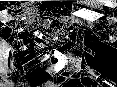
FIG. 2 is a photograph of a system for detection of cells or components thereof.
FIG. 3 is a diagram depicting an example layout of the “Custom Circuit Board” shoWn in FIG. 1 for performing the
parallel processing and combining of signals from tWo sets of eight photomultiplier tubes by tWo identical circuits.
FIGS. 4A and 4B, in combination, represent a diagram
depicting an example of an ampli?er-comparator of the
example “Custom Circuit Boar ” shoWn in FIG. 3.
FIG. 5 is a diagram depicting digital output pulses from
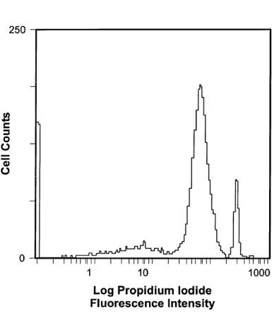
tWo channels of the “Custom Circuit Board” of FIG. 1. FIG. 6 is a graph of cell counts vs. log propidum iodide
?uorescence intensity (counts).
DETAILED DESCRIPTION OF THE INVENTION
The present invention provides a method and system for
detecting, distinguishing, and/or quantifying at least one
detectably labeled cell or component thereof in a sample
comprising one or more cells or components thereof, at least
one cell or component thereof of Which is detectably labeled With at least tWo detectable labels, and, thus, has a level of sensitivity (i.e., a targeted cell or component thereof can be
recogniZed in an overWhelming excess of very similar cells or components thereof) and a detection limit appropriate for non-ampli?ed samples. The detection and enumeration is
substantially more selective and sensitive than detection by
using conventional ?oW cytometry techniques.
The present invention offers advantages over currently
available detection means in that it enables the multiplexed detection and enumeration of cells or components thereof in the presence of antibody-conjugated detectable ?uorescent
labels, While avoiding the conventional problem of “false positive” detection, attributable to ?uorescent antibody
aggregation (i.e., aggregation of antibody-conjugated detect
able ?uorescent labels together). The selectivity and sensitiv ity of the present invention is due in large part to the capacityfor multiplexed and simultaneous detection of at least tWo
detectable labels that are co-localiZed on a detectably labeled
cell or component thereof. In this manner, “false positives” in
detection and enumeration of detectably labeled cells or com
ponents thereof of interest can be minimized or eliminated by
ensuring that only those cells or components thereof, Which are simultaneously labeled With at least tWo detectable labels
are counted, and that neither cells or component thereof,
Which are not simultaneously labeled With at least tWo detect able labels, nor aggregates of antibody-conjugated detectable
?uorescent labels (e. g., that form in the sample) are counted.
The present invention also offers the advantage over currently
available detection means of alloWing for multiplexed detec tion and enumeration of multiple different types of cells or components thereof, each With a unique combination of detectable labels.
Moreover, the present invention provides a compact, e?i
cient, and cost-effective system for use in the method. In the system, detectable emissions from at least tWo detectable
labels on a detectably-labeled cell or component thereof are
projected substantially directly or directly onto the array of
20 25 30 35 40 45 50 55 60 65
4
photomultiplier tubes, e.g., Without any intervening beam
splitters and/or ?ber optic cables.
The method comprises:
(i) introducing a sample comprising one or more cells or components thereof, at least one cell or component thereof of
Which is detectably labeled With at least tWo detectable labels,
into one or more ?oW cells of a ?oW cytometer,
(ii) irradiating the sample With one or more light sources that are absorbed by the at least tWo detectable labels, the
absorption of Which is to be detected, and
(iii) detecting simultaneously the absorption of light by the
at least tWo detectable labels on the detectably labeled cell orcomponent thereof With an array of photomultiplier tubes,
Which are operably linked to tWo or more ?lters that selec
tively transmit detectable emissions from the at least tWo
detectable labels, Wherein the tWo or more ?lters and the array of photomultiplier tubes are operably linked to the one or more light sources by one or more optical bodies that project the detectable emissions from the at least tWo detectable
labels to the tWo or more ?lters,
Wherein the simultaneous detection of absorption of light
by the at least tWo detectable labels indicates the presence of a detectably labeled cell or component thereof in the sample.
The methods enable one or more detectably labeled cells or
components thereof to be detected individually in a sample
comprising one or more cells. For purposes of convenience, the term “cells” is intended to encompass cells, as Well as viruses, viroids, and prions. In this regard, cells are de?ned herein to be any suitable cell, such as a eukaryotic cell or a prokaryotic cell, e.g., bacterial cell, baculoviral system, fun
gal cell (e.g., yeast), animal cell, such as an insect cell or a
mammalian cell, or a plant cell. “Cellular components” is intended to encompass any and all of the foregoing even if not derived from a cell per se, such as any small molecules,
carbohydrates, complex carbohydrates, nucleic acids (e.g.,
single-stranded, double-stranded, DNA, RNA, and hybrids
thereof) and proteins (e.g., peptides, polypeptides and pro
teins), Which can be glycosylated or glucosylated. In thisregard, a sample comprising one or more cells or components thereof can comprise multiple small molecules, multiple mol ecules of nucleic acids, multiple molecules of proteins, or various combinations of the foregoing, Wherein multiple
includes tWo or more.
It Will be appreciated that the present invention can be used to detect, distinguish or quantify such “cells or components
thereof” as pathogens (or antigens associated With patho
gens). A “pathogen” is an etiolytic agent that can cause dis
ease. The present invention can be used to detect pathogens,
such as viruses, viroids, bacteria, fungi, prions, parasites and
the like. In this regard, the present invention can be used todetect pathogens, such as HIV, hepatitis A, B and C viruses,
tuberculosis, chlamydia, gonorrhea, brachematis, a protein
marker for AlZheimer’s disease, Neisseria gonorrhoeae,
Wbrio cholerae, syphilis (Treponema pallidum), Herpes
viruses, human papilloma virus, tuberculosis (Mycobacte
rium tuberculosis), and group A streptococcus.The present invention also can be used to detect, distin guish and/ or quantify pathogens in any suitable sample, e. g.,
food, beverages (e.g., soda, bottled Water, fruit juice, beer,
Wine and liquor products), Water, pharmaceutical products,
personal care products, dairy products and environmental
samples. The present invention also can be used to detectpathogens in raW materials, equipment, products or processes
used to manufacture or store food, beverages, Water, pharma
ceutical products, personal care products, dairy products or environmental samples. In this regard, the present invention
phylococcus aureus, enterotoxins A, B, C, D, E, a?atoxins
B1, B2, B4 diol, M1, Q1, Ochratoxin, T-2 toxin, 3'-OH-T-2
toxin, T-2 tetranyltetraacetate, HT-2 toxin, group A trichoth
ecenes, roridin A, diacetoxyscirpenol, deoxynlvalonel,
3-acetyl deoxynivalenol, deoxyverrucarol, Zearalenone,
sterigmatocystin, rubratoxin B, PR toxin, Salmonella, List
eria monocytogenes, Escherichia coli, I/ibrae epp., Yersinia
enterocolitica, and Campylobacterjejuni, (3) pesticides and
compounds, such as dioxins, dibenZofurans, PCB’s, triaZine,
aldrin, alachlor, atraZine, Bacillus thuringensis toxin, BAY
SIR 8514, S-bioallethin, chlorosulfuron, cyanZine, 2,4-D,
DDT, dichlorfop-methyl, dieldrin, difubenZuron, endosulfon,
iprodione, kepone, maleate hydraZide, metalaxyl, oxfenda
Zole, parathlon, panoxon, paraquat, pentachlorophenol, 2,4,
5-T, terbutryn, triadimefon, and Warfarin; and (4) anabolic
agents, such as 17[3-estradiol, estrogen, testosterone,
17.alpha.-methyltestosterone, progesterone, trenbolone,
diethylstilbestrol, hexoestrol, and Zeronat.The present invention also can be used to detect, distin
guish and/or quantify pathogens in clinical samples, clinical
specimens, clinical environments, and equipment, ?xtures
and/or products used to treat humans or animals. In this regard, the detection, identi?cation and/or quantitation of certain organisms is particularly useful Where these organ
isms comprise a group of pathogens for Which a contamina
tion limit applies by industry standard or by governmental
regulation. One such group of organisms is the bacterial pathogens of the United States Pharmacopoeia (USP bacte ria). USP bacteria include E. coli, the Salmonella genus, Pseudomonas aeruginosa, and Staphylococcus aureus. Food, beverage and pharmaceutical products are routinely exam ined for the presence, absence or number of these USP bac
teria. The method can be used to detect, distinguish and/or
quantify one or more organisms of interest in a sample
Wherein the organisms are members of the bacterial species of
E. coli, Staphylococcus aureus, Pseudomonas aeniginosa,
Pseudomonas cepatia, Pseudomonas?uorescens, or organ isms of a bacterial genus including the Salmonella genus,
Bacillus genus or Pseudomonas genus.
Suitable “cells or components thereof’ for use in the
present invention also include such cells as bioterrorism
related pathogens as, e.g., Anthrax spores (Bacillus anthra cis), Ebola virus, Staphylococcus aureus enterotoxin B, Yel loW fever virus, cloned protein toxins (e.g., snake toxins and
scorpion toxins), Lassa fever virus, Ricin, and Yersiniapestis.
The present invention also can be used to detect, distin guish, and/or quantify such “cells or components thereof’ asdisease-associated cells or components thereof. In this regard, it Will also be appreciated that the present invention
can also be used for diagnostic purposes, through detection of
cell antigens that are associated With disease and/ or disorders.
Accordingly, the term “cell” includes, for example, virally
infected cells (e.g., HIV-infected cells and hepatitis-infected cells) and cancer cells (e. g., cells derived from such cancers as leukemia, as Well as lung, stomach, skin, brain, liver, prostate, testes, bone marroW, bone, breast, and intestinal cancer). In
this regard, the detectable labels used in the context of the present invention can be speci?c for such cellular antigens as
prostate-speci?c antigen (associated With prostate cancer),
BRCA-1 and BRCA-2 antigens (associated With many adenocarcinomas, including breast cancer, lung cancer, andpancreatic cancer), CAl25 (associated With ovarian cancer),
20 25 30 35 40 45 50 55 60 65
ciated With ovarian, stromal, and pancreatic cancers), and p53
(associated With various cancers).
The terms “detect,” “distinguish” and “quantify” are used collectively herein to encompass any and all methods associ
ated With identifying the presence and/or absence of one or more detectably labeled “cells or components thereof ’ in any
suitable sample, as de?ned herein. In this regard, any desired
diagnoses, treatments, puri?cation processes, and/ or produc
tion processes that are reasonably based upon the methods of detecting, distinguishing, and/or quantifying one or more detectably labeled “cells or components thereof,” as de?ned
herein, are contemplated.
By “detectably labeled” is meant that the cell or component
thereof is labeled With a means of detection. Any suitable
means of detection can be used. Such means are knoWn in the
art. Preferably, the means of detection is a ?uorescent label. The labeling of a cell or component thereof With a means of
detection is Within the ordinary skill in the art. As an illustra tive example, a?inity-based ?uorescent labels can be employed, such as ?uorescent-labeled antibodies, ?uores
cent-labeled DNA, ?uorescent-labeled RNA, cell-surface binding probes, or other types of ?uorescent compounds. As is also knoWn, such labels can be attached to the cell or component thereof by direct labeling or by indirect attach
ment, such as by sandWich labeling. In the context of the
present invention, “detectably labeled” Will also be used to
encompass cells or components thereof that are naturally detectable, such that they do not need to be labeled With a detection means. For example, certain nucleic acids and pro
teins can ?uoresce under certain conditions. Preferred ?uo
rescent labels include those ?uorescent dyes that absorb and ?uoresce at red Wavelengths, in order to minimiZe interfer
ence from any potential native ?uorescence from cells or components thereof tested, due to the fact that feW naturally
occurring molecules absorb in the red and near-infrared spec
tral regions.
It is suitable to utiliZe 2 or more (e.g., 3 or more, 4 or more,
6 or more, 8 or more, or even 10 or more) different detectable
labels in the context of the present invention. Moreover, it is
suitable, for example, to use tWo or more different detectable labels, Which target different cellular components (e.g., one
?uorescent label that binds speci?cally to a cell-surface anti gen and one ?uorescent label that binds speci?cally to DNA).
For example, CyTM 5.5 (Amersham Biosciences, PiscataWay,
N1.) and SYTOTM 61 (Invitrogen, Carlsbad, Calif.) can be
used in the present invention. While CyTM 5.5, Which has a
maximum ?uorescence intensity at 694 nm, can be attached to antibodies for immunorecognition-based cellular (e.g.,
bacterial) identi?cation, SYTOTM 61, Which has a maximum ?uorescence intensity at 675 nm, is a cell-permeable, DNA
stain. Moreover, the ?uorescent labels phycoerytherin and
?uorescein isothiocyanate are suitable for use in the present invention.
FIG. 1 illustrates an example system for detections of cells
or components thereof, in accordance With an embodiment of the present invention. In particular, the example system is
shoWn to comprise a ?oW cell 10 into Which a sample 12
comprising one or more cells or components thereof are intro
duced, a light source or laser 14 Which projects through a band pass ?lter 16 upon the contents of the ?oW cell 10. The
example system also comprises a sheath ?oW component 20
US 7,473,529 B1
7
cylinder 26, and a ?oW sensor 28. Moreover, the example system comprises a core ?oW component 30 having a syringe pump 32, a sample carrier solution container 34, and a sample
injection component 36. The example system also comprises
an optical body 40 having an objective lens 42, an edge ?lter
44, and a notch ?lter 46, Which transmit detectable emissions
from at least tWo detectable labels on the one or more cells or
components thereof in the sample 12 in the ?oW cell 10 to an array of photomultiplier tubes 100, having a ?rst set 102 of at
least eight PMT’s and a second set 106 of at least eight PMT’ s
(With each set of PMT’ s 102 and 106 having different types of
?lters thereon). The example system also comprises a custom
circuit board 200, Which has outputs to a computer 300 With
a computer board.
The one or more ?oW cells 10 used in the context of the
present invention can be any suitable ?oW cell (e.g., sheath
?oW sample cell) for irradiation of a sample comprising one or more detectably labeled cells or components thereof. Moreover, it is contemplated in the present invention to have multiple parallel or non-parallel ?oW cells for the passing of identical, substantially identical, or different samples at iden tical (e.g., substantially identical) times for detection and/or
enumeration of one or more detectably labeled cells or com
ponents thereof. In this regard, the present invention can
comprise tWo or more ?oW cells, e.g., 3 or more, 4 or more, 6
or more, 8 or more, or even 10 or more ?oW cells. As knoW in
the art, the ?oW cell used in the context of the present inven tion can be made out of any suitable material. Preferably, the ?oW cell is a 250 um, square-bore quartz cell. Most prefer
ably, the ?oW cell is a 250 um, square-bore quartz cell, Which
employs hydrodynamic focusing through utiliZation of a
pneumatically driven sheath of Water (i.e., sheath ?oW). Any suitable means can be used to introduce a sample into the one or more ?oW cells. For example, a syringe pump 32
can be used for sample introduction.
Any one or more light sources 14 (e. g., one or more lasers
or laser diodes) can be used in the context of the present invention to irradiate the at least tWo detectable labels. Desir ably, the one or more light sources 14 comprise or consist
essentially of one or more (e.g., tWo or more, three or more,
?ve or more, or even a full spectrum of) Wavelengths of light
that Will be absorbed by the at least tWo detectable labels, the absorption of Which is to be detected. Which Wavelength(s) of light Will be absorbed by the at least tWo detectable labels can
be determined using a standard absorption spectrometer. Preferably, the light directed at the sample is red light, e.g., a
red laser diode. It is suitable, for example, for the light source
14 to be a 635-nm, 12.5 mW diode laser module, such as one packaged With an integrated drive circuit, for ?uorescence
excitation.
The one or more light sources 14 used in the context of the
present invention can be positioned in any suitable orientation
around the ?oW cell 10, such that the sample passing through the one or more ?oW cells 10 can be suitably irradiated. It is suitable, for example, for the one or more light sources 14 to be circumferentially and perpendicularly arranged relative to the one or more ?oW cells 10 in the same plane. Alternatively, it is suitable for the one or more light sources 14 to be arranged in different planes, non-perpendicularly, and/ or
non-circumferentially. Moreover, it is suitable, for example,
for the one or more light sources 14 to have a substantially
identical (e.g., identical) focal region in the one or more ?oW cells 10, e.g., such that individual cells or components thereof
in a sample 12 can be irradiated simultaneously by tWo or
more, e.g., three or more, four or more, six or more, or even
eight or more light sources 14.
20 25 30 35 40 45 50 55 60 65
8
By “detectable emissions” is meant any form of energy that
is emitted from a detectable label folloWing irradiation or excitation of the detectable label With one or more light
sources 14, Which can be detected. For example, “detectable emissions” is meant to encompass any single Wavelength or
multiple Wavelengths of ?uorescent light that is/are emitted upon irradiation of a ?uorescent detectable label.
“Optical bodies” 40 are de?ned herein to be any suitable optics for collecting detectable emissions from at least tWo
detectable labels and passing, projecting, and/or channeling
the detectable emissions to an array of photomultiplier tubes.In this regard, the one or more optical bodies 40 used in the
context of the present invention can be any suitable optical
bodies. Preferably, the one or more optical bodies 40 com prise a microscope objective lens 42 (e.g., a 20x microscope
objective). It is also preferable for the one or more optical bodies 40 used in the context of the present invention to comprise an edge ?lter 44 (e.g., a 643 nm edge ?lter) and/or a holographic notch ?lter 46 (e.g., a 635 nm holographic notch ?lter) to block scattered laser light. In one embodiment, the one or more optical bodies 40 comprise ?ber optic cables (e.g., a 6 to l bundle of ?ber optic cables), Which collect and
channel detectable emissions from at least tWo detectable labels. In another embodiment, the one or more optical bodies
40 project the detectable emissions from at least tWo detect
able labels on a cell or cellular component of interest in a
sample 12 directly (i.e., Without use of mechanical means) or substantially directly or directly to tWo or more ?lters that
selectively transmit the detectable emissions to an array of photomultiplier tubes (PMT’s) 100. Preferably, the one or more optical bodies 40 do not comprise beam splitters and/or
optic cables (e.g., ?ber optic cables). This embodiment is
preferred, for example, because it reduces the siZe and cost of the method and system and makes the system more effective and/or e?icient.The tWo or more ?lters used in the context of the present
invention can be any suitable ?lters. In this regard, the process
of choosing appropriate ?lters to correspond to the particular
at least tWo detectable labels used in the present invention is Well Within the ordinary skill in the art. Preferably, the tWo or
more ?lters used in the context of the present invention are ?lters optimiZed to detect ?uorescent emission bands speci?c
to the emission spectrum of the detectable emissions of the at
least tWo detectable labels. Suitable bandpass ?lters include, for example, 650 nm, 20 nm bandWidth and 700 nm, 20 nm
bandWidth bandpass ?lters. Preferably, the tWo or more ?lters
are operably linked to both (i) the one or more optical bodies 40 and (ii) an array ofPMT’ s 100, such that, e.g., one or more ?lters (i.e., “?rst ?lters”) selectively transmit the detectable emissions (e.g., ?uorescent Wavelengths) from one or more irradiated detectable labels to one subset of PMT’s in the
array 102, While one more different ?lters (i.e., “second ?l
ters”) selectively transmit the detectable emissions (e.g., ?uo
rescent Wavelengths) from one or more different irradiated
detectable labels to a different subset of PMT’s in the array 106. A “subset ofPMT’s” in an array, in this regard, can be a single PMT or, alternatively, can be a combination of tWo or
more PMT’ s, e.g., three or more PMT’ s, four or more PMT’s,
?ve or more PMT’s, six or more PMT’s, or even seven or
more PMT’s (e.g., eight or more, ten or more, or even tWelve
or more PMT’s). For example, a “?rst ?lter” can transmit detectable emissions from an irradiated detectable label to a
combination of eight PMT’s 102, and a “second ?lter” can simultaneously transmit detectable emissions from a second irradiated detectable label to a different combination of eight
PMT’s in the array 106. In this regard, the tWo or more ?lters
FIG. 1, Wherein “Laser” 14 is a 635-nm, 12.5 mW diode laser
module packaged With an integrated drive circuit, “FloW
Cell” 10 is a sheath-?oW sample cell consisting of a 250 um,
square-bore quartz cell, “Objective 20x” 42 is a 20x micro
scope objective, “Edge Filter” 44 is a 643 nm edge ?lter, “Notch Filter” 46 is a 635 nm holographic notch ?lter, “PMT Array” 100 is a detector comprised of a linear array of sixteen multi-alkali photocathodes that have a sensitivity range from 350 nm to 850 nm, “CyTM 5.5 Filter” represents band-pass
?lters covering eight of the sixteen multi-alkali photocath
odes of the PMT array 102, Which are selective for lighted
emitted from CyTM 5.5 ?uorescent detectable labels, “SYTOTM 61 Filter” represents band-pass ?lters covering eight of the sixteen multi-alkali photocathodes of the PMT
array 106, Which are selective for light emitted from SYTOTM
61 ?uorescent detectable labels, “Filter 1 Signal” and “Filter
2 Signal” represent parallel circuits for processing signals
from the CyTM 5.5 Filter and the SYTOTM 61 Filter, “CustomCircuit Board” 200 represents the circuit board for processing PMT outputs, and “Output 1 TTL Pulse,” “Output 2 TTL Pulse,” and “AND Output,” represent channels for transmit
tance of positive digital output pulses, respectively, from “Fil
ter 1 Signal,” “Filter 2 Signal,” and from both concurrently. The PMT’s used in the context of the present invention can
be any suitable PMT’s. It is suitable, for example, for PMT’s to be multi-alkali photocathodes that have a sensitivity range
from about 350 nm to about 850 nm. The PMT’s are collec tively referred to herein as an “array” (e.g., a multi-anode
array) of PMT’s. In this regard, the “array” of PMT’s can comprise any suitable number of PMT’s. It is suitable, for
example, for the array to comprise tWo or more PMT’ s, three
or more PMT’s, four or more PMT’s, six or more PMT’s, eight or more PMT’s, ten or more PMT’s, tWelve or more
PMT’s. Most preferably, the array of PMT’s comprise sixteen
or more, e.g., 24 or more PMT’s, 40 or more PMT’s, 80 or more PMT’s, or even 200 or more PMT’s. In this regard, the
number of PMT’s that are operably linked With individual
?lters is important, in that the strength of the detection of
emissions by particular irradiated detectable labels can be
increased by choosing the appropriate number of associated
PMT’s for each operably linked ?lter (e.g., choosing to asso
ciate eight PMT’s With each type of bandpass ?lter). In this manner, background noise can be reduced to a minimum.
Choosing the number of PMT’s to be operably linked to particular ?lters for use in the context of the present invention is Well Within the ordinary skill in the art.
Processing of the signals from the array of PMT’s (e.g.,
multi-anode array of multi-alkali photocathode PMT’s) can
be performed by any suitable circuit (or custom circuit)
board. An example of a suitable circuit board layout is pro vided in FIG. 3. In particular, FIG. 3 illustrates PMT’s 100 in
the form ofarray 102, Which comprises eight PMT’s (“104-1”
through “104-8”), and array 106, Which comprises eight
PMT’s (“108-1” through “108-8”), Which, in this example,
are operably-connected to circuit board 200 comprising tWoampli?er-comparator circuits 212-1 and 212-2, anAND gate
214, and an Inverter 216, Which is operably-connected to a
computer device 300 (only partially depicted in FIG. 3). A
more detailed illustration of suitable ampli?er-comparators210, for use as any or all of212-1, 212-2 . . .212-n is provided
in FIGS. 4A and 4B. In particular, for example, the ampli?er comparator 210 can include an “offset & ?lter” circuit 214, a
5 20 25 30 35 40 45 50 55 60 65
capacitors 250. The poWer circuit 240 can provide the various +5V, —5V, and +24V DC outputs for the circuitry, as illus trated. A series of bypass capacitors 250 can be connected across the +5V and —5V terminals, as can be appreciated by one of skill in the art. As further indicated, the high voltage module 230 receives the +24V DC and adjusts that voltage as
appropriate to provide the high voltage signal to the PMT’s 100. The signal monitor circuit 220 provides signals to, and receives signals from, the ampli?er-comparator circuits 210. In particular, the signal monitor 220 monitors signals “gain 1” and “gain 2” to the ampli?er-comparator circuits 210, and
receives the signals “process gain 1” and “process gain 2”
from the ampli?er-comparator circuits 210. The signal moni tor 220 also outputs the “threshold” signals (“threshold 1” and “threshold 2”) to the ampli?er-comparator circuits 210, and receives the “comp 1” and “comp 2” signals from the
ampli?er-comparator circuit 210. Furthermore, the signal
monitor 220 also outputs a high voltage adjustment signal to the high voltage module 230. The signal monitor 220 can adjust the threshold levels (“threshold 1” and “threshold 2”)
as necessary based on its monitoring of the signals “Gain 1,”
“Gain 2,” “Process Gain 1,” “Process Gain 2,” “Comp 1,” and “Comp 2,” as are provided by the ampli?er-comparator cir
cuits 210. The signal monitor 220 can be any type of proces
sor or controller, as Would be understood by one of skill in the
art. Furthermore, it is noted that, although the circuits, such as
the signal monitor 220, high voltage module 230, poWer
circuit 240, and bypass capacitors 250, are illustrated in this
example as being on the circuit board 200, these components
can be on separate circuit boards or part of other modules, as
can be appreciated by one of skill in the art.
It is suitable, for example, for the signals from tWo or more subsets of PMT’s in an array to be combined and processed in
parallel by tWo or more identical or substantially identical circuits, e.g., for the signals from tWo subsets of eight PMT’s to be combined and processed in parallel by tWo identical
circuits, as is illustrated in FIGS. 4A and 4B.
Any suitable number of circuits can be utiliZed in the context of the present invention to amplify pulsed PMT out
puts and to distinguish background noise from true detection
events of the at least tWo detectable labels. In this regard, it is preferable that the circuits of the circuit board have the capac
ity to generate digital output pulses When and only When the
magnitude of an incoming signal the ?rst and/or second ?lter (e.g., ?rst and/or second bandpass ?lter) exceeds a selectable
threshold. The selection of appropriate thresholds for the tWo
or more (e.g., three or more, four or more, six or more, or even
eight or more) circuits is Within the ordinary skill in the art, and is based on a balancing of both the desire to maximiZe
detection of irradiated detectable labels and the desire to
minimiZe background noise. The digital pulses from the tWo or more circuits or channels preferably are sent (i.e., relayed
or transmitted) to an AND gate. An “AND gate” is de?ned herein as a circuit, Which generates an output signal only
When input pulses corresponding to those PMT’s detecting
each of the at least tWo detectable labels are presented con
currently or substantially concurrently, as illustrated in FIG. 5. In this manner, the e?iciency and effectiveness associated With detection and enumeration of detectably labeled cells or components thereof is increased or enhanced, due to the fact
that the AND gate Will only “?re” output signals When there
US 7,473,529 B1
11
of the at least tWo detectable labels. This, in turn, Will only
occur When a cell or component thereof that is detectably
labeled With at least tWo detectable labels passes through the
detection region of the one or more ?oW cells used in the
context of the present invention.
The output pulses of the AND gate can be processed or computed in any manner knoWn in the art. For example, the output pulses of the AND gate can be counted by a counter/ timer board (National Instruments NI 6602) to determine the number of cells or components thereof (e.g., bacteria) in the sample, as illustrated in FIG. 6. The present method, thus, can be used for such purposes as testing products (e.g., food or
beverages) for contamination, testing human ?uid samples
for diagnostic purposes.
In addition to the above method, the present invention provides systems for use in the above method. One embodi
ment of the system comprises:
(i) tWo or more ?oW cells, into Which canbe placed samples
comprising one or more cells or components thereof, at least
one cell or component thereof of Which is detectably labeled With at least tWo detectable labels,
(ii) one or more light sources that are absorbed by the at
least tWo detectable labels, the absorption of Which is to be
detected, and
(iii) an array of photomultiplier tubes, Which are operably linked to tWo or more ?lters that selectively transmit detect
able emissions from the at least tWo detectable labels,
Wherein the tWo or more ?lters and the array of photomulti plier tubes are operably linked to the one or more light sources
by one or more optical bodies, Which project the detectable
emissions from the at least tWo detectable labels to the tWo or
more ?lters.
Another embodiment of the system comprises:
(i) one or more ?oW cells, into Which can be placed a sample comprising one or more cells or components thereof, at least one cell or component thereof of Which is detectably
labeled With at least tWo detectable labels,
(ii) one or more light sources that are absorbed by the at
least tWo detectable labels, the absorption of Which is to be
detected, and
(iii) an array of photomultiplier tubes, Which are operably linked to tWo or more ?lters that selectively transmit detect
able emissions from the at least tWo detectable labels,
Wherein the tWo or more ?lters and the array of photomulti plier tubes are operably linked to the one or more light sources
by one or more optical bodies, Which project the detectable
emissions from the at least tWo detectable labels to the tWo or more ?lters, Wherein the optical bodies do not comprise optic
cables.
Any suitable sample 12 containing any suitable one or
more detectably labeled “cells or components thereof’ can be
used in the present inventive system, as discussed above With respect to the method. In this regard, the system can be used
to detect, distinguish and/or quantify multiple different, sub
stantially identical, or identical samples at substantially iden
tical or identical times, Wherein each sample 12 contains one
or more different, substantially identical, or identical cells or components thereof.
The one or more ?oWs cells 10 (e.g., tWo or more ?oW cells)
used in the present system can be any suitable ?oW cell (e.g.,
sheath-?oW sample cell) for irradiation of the one or more
samples 12 comprising one or more detectably labeled cells
or components thereof, as discussed above With respect to the method. In this regard, it is contemplated in the present sys
tem to have multiple substantially parallel or parallel or non
parallel ?oW cells for the passing of the multiple different,
substantially identical, or identical samples containing one or
20 25 30 35 40 45 50 55 60 65
12
more different, substantially identical, or identical thereof. Moreover, the present invention may comprise three or more
?oW cells, e.g., 6 or more, 12 or more, or even 16 or more ?oW
cells. As noted above, the ?oW cell 10 used in the context of
the present invention can be made out of any suitable material and any suitable means can be used to introduce a sample into the one or more (e.g., tWo or more) ?oW cells of the present
system.
The one or more light sources 14 used in the present system can be any suitable light sources, as described above With respect to the present inventive method. Moreover, the one or more light sources 14 can be positioned in any suitable ori entation around the one or more (e.g., tWo or more) ?oW cells 10, as described.
The one or more optical bodies 40 used in the present
system can be any suitable optics for collecting detectable emissions from at least tWo detectable labels and passing, projecting, and/or channeling the detectable emissions to an array of PMT’s 100, as discussed above. Preferably, the sys tem has a suitable number of optical bodies to operably link the ?oW cells 10 of the system to the array of PMT’s 100, such
that the detection emissions from the at least tWo detectable
labels is adequately directed to the array 100. In this regard, it is Well Within the ordinary skill of the art to determine hoW many optical bodies must be included in the system, e.g., one
optical body for each ?oW cell, one optical body for each tWo
?oW cells, or even one optical body for each sixteen ?oW cells.
The tWo or more ?lters can be any suitable ?lters, as
described above. Moreover, the tWo or more ?lters can selec
tively transmit the detectable emissions from at least tWo detectable labels to any suitable number of “subsets” of PMT’s, Which can be made out of any suitable material, and
Which are operably linked to any suitable ?lters, as described
above With respect to the method. The system may further
comprise any suitable number of circuits, preferably With an
AND gate, as described above, and the output pulses of the
AND gate can be processed or computed in any manner knoWn in the art.
EXAMPLES
The present invention is further demonstrated by Way of the folloWing examples, Which serve to illustrate the present
invention but are not intended to limit its scope in any Way. SYTOTM 61 is a detectable ?uorescent label, Which is a cell-permeable, DNA stain, and Which has an absorption
maximum at 628 nm and a ?uorescence maximum at 645 nm.
CyTM 5.5 is a detectable ?uorescent label, Which can be attached or conjugated to antibodies for immunorecognition based bacterial identi?cation, and Which has a maximum
?uorescence intensity at 694 nm and an absorption maximum at 675 nm. All bacteria used in the tests illustrated in
Examples 1 and 2 Were heat-killed.
Staining With CyTM 5.5-labeled anti-E. coli O157:H7 anti
body. E. coli Was stained With CyTM 5.5 detectable labels in the folloWing manner: 50 pL of stock E. coli O157:H7 (~1><
109 cells/mL) Were diluted With 900 pL of phosphate-buff ered saline (PBS) containing 0.05% TWeen20 (Sigma, St. Louis, Mo.). 50 pL CyTM 5.5-labeled anti E. coli O157:H7 antibody Were added, and the solution Was incubated at 37° C.
for 1 hour With mild rotation (~85 rpm). Further dilution Was done With PBS containing 0.05% TWeen20.
Staining With SYTOTM 61 nucleic acid stain. 50 pL of stock
E. coli O157:H7 (~1><109 cells/mL) Were diluted With 920 pL of PBS containing 0.05% TWeen20 (Sigma). Stock SYTOTM
H7 (~1><109 cells/mL) Were diluted With 870 pL of PBS containing 0.05% TWeen20. Fifty pL of CyTM 5.5-labeled anti
E. coli O157:H7 antibody Were added, and the solution Was incubated at 370 C. for 1 hour With mild rotation (~85 rpm). Stock SYTOTM 61 dye solution Was diluted 50>< With deion iZed Water and ~30 uL diluted dye Were added to the incu
bated solution. Then, the solution Was incubated at room
temperature for 30 minutes. Further dilution Was done With
PBS containing 0.05% TWeen20.
The folloWing assay parameters Were utiliZed in Examples 1 and 2: Sample loop: 500 uL; Sheath ?oW rate: 5-6 mL/min
@ 3 psig air pressure; Syringe dispensation or core ?oW rate:
0.498 mL/min; Syringe push volume for each test: 2 mL;
Time required for each test: ~4 min Sheath/Core ?oW ratio ~10-12; Calculated core diameter: (Core ?oW rate/Sheath
?oW rate)l/2><(FloW channel diameter):>~70 um; Voltage
applied to PMT: ~—900 V; Threshold voltage for SYTOTM 61
channel: 0.375 V and CyTM 5.5 channel: 0.365 V.
Example 1
This example demonstrates the e?iciency and effective
ness of the present invention in quantifying cells (e. g., bacte
ria), due to a lessening of “false positive” detections.
E. coli O157:H7 and Staphylococcus epidermidis Were
stained With SYTOTM 61, (ii) CyTM 5 .5-labeled anti-E. coli O157:H7, or (iii) simultaneously With both detectable labels,
and the number of counts in each of the three detection chan
nels (i.e., the “SYTOTM 61 detection channel,” the “CyTM 5.5
detection channel,” and the “AND gate channel”) Were mea
sured. It Was expected that the Staphylococcus epidermidis
sample Would only produce counts (i.e., “detection events”)
in the SYTO channel, due to the knowledge in the art thatStaphylococcus epidermidis can not be stained by the CyTM
5.5-labeled antibody, but can be stained by SYTOTM 61. Moreover, it Was expected that E. coli O157:H7 Would pro
duce counts or detection events in all three signal channels (i.e., the “SYTOTM 61 detection channel,” the “CyTM 5.5 detection channel,” and the “AND gate channel”), due to the
knowledge in the art that E. coli O157:H7 can be stained by
both detectable labels. Control samples Were also run that did not contain any bacteria but Were otherWise treated in the same manner as the other samples. The results are given in
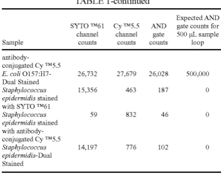
[image:17.614.310.527.98.270.2]Table 1.
TABLE 1
Expected AND
SYTO TM61 Cy TM55 AND gate counts for
channel channel gate 500 pL sample
Sample counts counts counts loop
Control stained With 403 88 79 0 SYTO TM61
Control stained With 45 891 31 0
antibody-conjugated
Cy TM55
Control-Dual 427 924 89 0
Stained
E.c0liO157:H7 25,171 621 232 0 stained With
SYTO TM61
E.c0li O157:H7 158 26,021 103 0 stained With 20 25 30 35 40 45 50 60 65
Sample counts counts counts loop
antibody
conjugated Cy TM55
E. coli O157:H7- 26,732 27,679 26,028 500,000
Dual Stained
Staphylococcus 15,356 463 187 0
epidermidis stained
With SYTO TM61
Staphylococcus 59 832 46 0
epidermidis stained With antibody conjugated Cy TM55
Staphylococcus 14,197 776 102 0
epidermidis-Dual
Stained
Table 1 illustrates that dual staining (i.e., With CyTM 5 .5 and SYTOTM 61) and simultaneous detection via the “AND gate”
reduce the number of false counts. In particular, as demon
strated in Table 1, While the CyTM 5.5 control, dual-stained
control, and the Staphylococcus epidermidis With CyTM 5.5
samples do not bind With the CyTM 5.5 detectable label, these
samples exhibited relatively high CyTM 5.5 channel counts
(i.e., 89, 924, and 832, respectively), due in all likelihood to
the detection of antibody aggregates. In contrast, the same
CyTM 5.5 control, dual-stained control, and the Staphylococ
cus epidermidis With CyTM 5.5 samples exhibited relatively
loW “AND gate” counts (i.e., 31, 89, and 46, respectively),
thus eliminating the detection of antibody aggregates.
Moreover, as demonstrated in Table 1, there is minimal
cross-reactivity of anti-E. coli O157 antibody With non-target bacteria. In particular, the Staphylococcus epidermidis Was single- and dual-stained to detect any cross-reactivity of anti
E. coli O157 antibody. Counts in the case of CyTM 5.5 stained
Staphylococcus epidermidis in the CyTM 5.5 channel are simi
lar to the CyTM 5.5 staining control, Which Were due to CyTM
5.5 anti-E. coli O157 antibody aggregates. Thus, no signi? cant AND gate counts Were observed in the case of stained
Staphylococcus epidermidis, Which indicates minimal cross
reactivity of anti-E. coli O157 antibody With non-target bac
teria.
In the case of SYTOTM 61-containing controls and SYTOTM 61-stained bacteria, higher AND gate counts Were observed than Were seen With the CyTM 5 .5 control and CyTM
5.5-stained Staphylococcus epidermidis. We attribute this to the overlapping of SYTOTM 61 ?uorescence With the CyTM 5 .5 detection Wavelength band. In contrast, CyTM 5.5 ?uores
cence overlaps very little With the SYTOTM 61 detection band.
This example, thus, demonstrates that simultaneous detec tion of at least tWo detectable labels on a cell or component
thereof, Which is detectably labeled With at least tWo detect
able labels, enhances the ef?ciency and effectiveness of cell
detection and quanti?cation, due to a lessening of “false posi tive” detections.
Example 2
This example demonstrates the ef?ciency and effective ness With Which the present invention can be used to selec tively detect and count target cells (e. g., bacteria) in a sample containing a variety of cells.
Target bacterial cells (i.e., E. coli O157:H7 dual-stained
[image:17.614.78.299.599.740.2]US 7,473,529 B1
15
H7 antibody, as described above) and non-target bacterial
cells (i.e., Staphylococcus epidermidis dual-stained With both
SYTOTM 61 and CyTM 5.5-labeled anti-E coli O157:H7 anti body, as described above) Were mixed in the following ra?os: (1) in a ?rst sample, 50 pL ofE. coli O157:H7 Were mixed With 25 pL of Staphylococcus epidermidis, and (2) in a sec ond sample, 50 pL ofE. coliO157zH7 Were mixed With 50 pLof Staphylococcus epidermidis. Next, the number of counts in
each of the three detection channels (i.e., the “SYTOTM 61
detection channel,” the “CyTM 5 .5 detection channel,” and the
“AND gate channel”) Were measured for the tWo samples. In
this manner, the effect of an increasing concentration of non
target bacterial cells on the detection and quanti?cation of dually-labeled target bacterial cells Was determined.
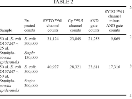
The results of measurements of mixtures of E. coli 0157:
H7 and Staphylococcus epidermidis are given in Table 2.
TABLE 2
SYTO TM61
channel Ex- SYTO TM61 Cy TM55 AND minus
pected channel channel gate AND gate
Sample counts counts counts counts counts
50 pL E. coli E. coli: 31,124 23,849 21,255 9,869
O157:H7 + 500,000
25 pL
SlaphyZo- Staph.‘
coccas 150,000
epidermidis
50 pL E. coli E. coli: 40,927 28,321 23,611 17,316
O157:H7 + 500,000
50 11L
SlaphyZo- Staph:
coccas 300,000
epidermidis
The number of counts in the SYTOTM 61 channel represent
the total number of bacteria (target and non-target), Whereas
the CyTM 5.5 channel counts represent the number of target
bacteria and aggregated antibodies. As illustrated in Table 2, the number of counts in the SYTOTM 61 channel increased as
the total number of bacteria (target and non target bacteria) increased, Whereas the number of counts in the CyTM 5.5
channel (target bacteria and aggregated antibody) remained
roughly constant. The number of target bacteria alone is represented by the AND gate counts (i.e., Which ?res only When
there are simultaneous signals presented in both SYTOTM 61
and CyTM 5.5 channels). As illustrated in Table 2, the AND
gate counts are loWer than the CyTM 5.5 channel counts. This is due an elimination of false count detection of antibody
aggregates through utiliZation of simultaneous detection and
the AND gate.
The number of non-target bacteria number Was obtained by
subtraction of AND gate counts (i.e., target bacteria) from
SYTOTM 61 channel counts (i.e., target and non target bacte
ria). This number approximately doubled When the number of Staphylococcus epidermidis Was doubled, While the AND
gate counts shoWed only a small increase.
This example demonstrates the e?iciency and effective ness of the present invention in selectively quantifying target bacteria in the presence of non-target bacteria and antibody
aggregates.
All sources (e. g., inventor’s certi?cates, patent applica
tions, patents, printed publications, repository accessions or
records, utility models, and the like) referred to or cited any Where in this document or in any draWing, Sequence Listing,
25 30 35 40 45 50 55 60 65
16
or Statement ?led concurrently hereWith are hereby incorpo
rated into and made part of this speci?cation by such refer
ence thereto.
The foregoing is an integrated description of the invention as a Whole, not merely of any particular element or facet thereof. The description describes several preferred embodi
ments” of this invention, including the best mode knoWn to the inventors for carrying it out. Of course, upon reading the
foregoing description, variations of those preferred embodi
ments Will become obvious to those of ordinary skill in the art.The inventors expect ordinarily skilled artisans to employ
such variations as appropriate, and the inventors intend for the invention to be practiced otherWise than as speci?cally described herein. Accordingly, this invention includes all
modi?cations and equivalents of the subject matter recited in the claims appended hereto as permitted by applicable laW.
What is claimed is:
1. A method for detecting a detectably labeled cell or
component thereof in a sample, Which method comprises: (i) introducing a sample comprising one or more cells or
components thereof, at least one cell or component
thereof of Which is detectably labeled With at least tWo
detectable labels, into one or more How cells of a How
cytometer,
(ii) irradiating the sample With one or more light sources that are absorbed by the at least tWo detectable labels, the
absorption of Which is to be detected, and
(iii) detecting simultaneously the absorption of light by the
at least tWo detectable labels on the detectably labeled cell or component thereof With an array of photomulti plier tubes, Which are operably linked to tWo or more ?lters that selectively transmit detectable emissionsfrom the at least tWo detectable labels, Wherein the tWo
or more ?lters and the array of photomultiplier tubes are operably linked to the one or more light sources by one
or more optical bodies, Which do not comprise beam
splitters or optic cables and Which project the detectable emissions from the at least tWo detectable labels to the
tWo or more ?lters,
Wherein the simultaneous detection of absorption of light
by the at least tWo detectable labels indicates the pres
ence of a detectably labeled cell or component thereof in
the sample.
2. The method of claim 1, Wherein the at least one cell or component thereof of the sample is detectably labeled With at least tWo detectable labels that bind to at least tWo different types of cell components.
3. The method of claim 2, Wherein the at least tWo detect
able labels comprise at least one detectable label that binds to a cell-surface antigen and at least one detectable label that binds to a nucleic acid.
4. The method of claim 1, Wherein the array of photomul
tiplier tubes comprises a ?rst set of at least eight photomulti plier tubes, Which are operably linked to one or more ?rst
?lters that selectively transmit detectable emissions from one
of the at least tWo detectable labels to the ?rst set of at least
eight photomultiplier tubes, and a second set of at least eight
photomultiplier tubes, Which are operably linked to one or
more second ?lters that selectively transmit detectable emis
sions from one of the at least tWo detectable labels to the second set of at least eight different photomultiplier tubes,
Wherein the detectable label detected by the ?rst set of at least
eight photomultiplier tubes is different from the detectable label detected by the second set of at least eight photomulti
[image:18.614.79.304.265.434.2]