Iowa State University Patents
Iowa State University Research Foundation, Inc.
5-11-1993
Subsurface sampler
Edward J. Jaselskis
Iowa State University
George F. Czapar
University of Illinois
Follow this and additional works at:
http://lib.dr.iastate.edu/patents
Part of the
Civil Engineering Commons
This Patent is brought to you for free and open access by the Iowa State University Research Foundation, Inc. at Iowa State University Digital Repository. It has been accepted for inclusion in Iowa State University Patents by an authorized administrator of Iowa State University Digital Repository. For more information, please [email protected].
Recommended Citation
Jaselskis, Edward J. and Czapar, George F., "Subsurface sampler" (1993).Iowa State University Patents. 34.
Subsurface sampler
Abstract
A subsurface sampler including a cylindrical casing with portholes to provide access below ground to sample
potentially hazardous substances without contaminating investigative probes that are inserted into the interior
cavity of the casing. The sampler has an inner sleeve that seals the portholes on the casing during the insertion
operation. After the casing is inserted into the ground, the inner sleeve is rotated such that the windows on the
sleeve and casing line up exposing the soil to a variety of investigative probes. A tab or wiper is attached to the
inner sleeve to clear soil blocking the portholes in the casing and to cut through the "smear" zone immediately
along side of the outer surface of the casing. Once the sampler casing is in the ground and portholes are open,
a sampling probe is inserted into the interior cavity of the casing following a track or guide system. When soil
characterization is complete, the portholes can be closed off by turning the inner sleeve and capping the casing
for future analyses, or the interior cavity may be filled with grout. The sampler casing is not intended to be
removed unless the area is excavated.
Keywords
Civil Construction and Environmental Engineering
Disciplines
Civil Engineering
United States Patent
[19JJaselskis et
al.
[54] SUBSURFACE SAMPLER
[75] Inventors: Edward J. Jaselskis; Ames, Iowa; George F. Czapar, Rochester, Ill.
[73] Assignee: Iowa State University Research Foundation, Inc., Ames, Iowa
[21] Appl. No.: 726,311
[22] Filed: Jul. 5,1991
[51] Int. Cl.s ... G01N 1/04 [52]
u.s.
Cl •... 73/864.64; 73/864. 74; 175/20 [58] Field of Search ... 73/864.64, 864.63, 864.74, 73/864.86, 863.82, 866.5; 175/20, 58; 166/100[56] References Cited
U.S. PATENT DOCUMENTS
1,256,413 2/1918 Wiswell ... 73/864.64 2,454,952 11/1948 Starkey et al ... 73/864.64 X 2,896,444 7/1959 Forman eta!. .. ~ ... 73/864.64 3,036,638 5/1962 Parsons ... 73/864.64 X 3,065,637 ll/1962 Landes ... 73/864.64 3,442,017 5/1969 Frerkel ... 73/864.64 X 3,596,719 8/1971 Koziski ... 175/20 4,072,059 2/1978 Hamilton ... 73/864.04 X 4,252,200 2/1981 Peterson ... 175/20 4,745,802 5/1988 Purfurst ... 73/155 4,950,844 8/1990 Hallmark et al ... 73/864.45 X
Z8
... I
-14
111111111111111111111111111111111111111111111111111111111111111111111111111
US005209129A[11]
Patent Number:
5,209,129
[45]
Date of Patent:
May 11, 1993
Primary Examiner-Tom Noland
Attorney, Agent, or Firm-Henderson & Sturm
[57] ABSTRACT
A subsurface sampler including a cylindrical casing with portholes to provide access below ground to sam-ple potentially hazardous substances without contami-nating investigative probes that are inserted into the interior cavity of the casing. The sampler has an inner sleeve that seals the portholes on the casing during the insertion operation. After the casing is inserted into the ground, the inner sleeve is rotated such that the
win-dows on the sleeve and casing line up exposing the soil to a variety of investigative probes. A tab or wiper is attached to .the inner sleeve to clear soil blocking the portholes in the casing and to cut through the "smear" zone immediately along side of the outer surface of the casing. Once the sampler casing is in the ground and portholes are open, a sampling probe is inserted into the interior cavity of the casing following a track or guide system. When soil characterization is complete, the portholes can be closed off by turning the inner sleeve and capping the casing for future analyses, or the inte-rior cavity may be filled with grout. The sampler casing is not intended to be removed unless the area is exca-vated.
11 Claims, 1 Drawing Sheet
~0
"_!./'"
U.S. Patent
...
I
--14
~-May 11, 1993
~0
,$_!/'"
--...
~illilll.--
18
5,209,129
-1
5,209,129
SUBSURFACES~LER
TECHNICAL FIELD
This invention relates to subsurface soil samplers and 5 more particularly to a subsurface sampler for highly contaminated soil characterization.
BACKGROUND ART
2
ing description of the best mode for carrying out the invention, particularly when reviewed in conjunction with the drawings, wherein:
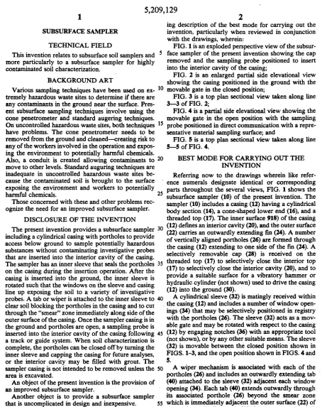
FIG. 1 is an exploded perspective view of the subsur-face sampler of the present invention showing the cap removed and the sampling probe positioned to insert into the interior cavity of the casing;
FIG. 2 is an enlarged partial side elevational view showing the casing positioned in the ground with the movable gate in the closed position;
FIG. 3 is a top plan sectional view taken along line 3-3 of FIG. 2;
FIG. 4 is a partial side elevational view showing the
movable gate in the open position with the sampling probe positioned in direct communication with a repre-sentative material sampling surface; and
FIG. 5 is a top plan sectional view taken along line 5-5 of FIG. 4.
Various sampling techniques have been used on ex- 10
tremely hazardous waste sites to determine if there are any contaminants in the ground near the surface. Pres-ent subsurface sampling techniques involve using the cone penetrometer and standard augering techniques. On uncontrolled hazardous waste sites, both techniques 15
have problems. The cone penetrometer needs to be removed from the ground and cleaned-creating risk to any of the workers involved in the operation and expos-ing the environment to potentially harmful chemicals.
Also, a conduit is created allowing contaminants to 20 BEST MODE FOR CARRYING OUT THE
move to other levels. Standard auguring techniques are INVENTION
inadequate in uncontrolled hazardous waste sites be- Referring now to the drawings wherein like refer-cause. the con~ated soil is brought to the sur_face ence numerals designate identical or corresponding exposmg the ~nvrronment and workers to potentially
25 parts throughout the several views, FIG. 1 shows the
harmful chem~cals. . subsurface sampler (10) of the present invention. The
~ose concerned w1t~ these and other problems rec- sampler (10) includes a casing (12) having a cylindrical ogruze the need for an unproved subsurface sampler. body section (14), a cone-shaped lower end (16), and a DISCLOSURE OF THE INVENTION threaded top (17). The inner surface 918) of the casing The present invention provides a subsurface sampler 30 (12) defines an interior cavity (20), and the outer surface including a cylindrical casing with portholes to provide (22) carries an outwardly extending fin (24). A number access below ground to sample potentially hazardous of vertically aligned portholes (26) are formed through substances without contaminating investigative probes the casing (12) extending to one side of the fm (24). A that are inserted into the interior cavity of the casing. selectively removable cap (28) is received on the The sampler has an inner sleeve that seals the portholes 35 threaded top (17) to selectively close the interior top on the casing during the insertion operation. After the (17) to selectively close the interior cavity (20), and to casing is inserted into the ground, the inner sleeve is provide a suitable surface for a vibratory hammer or rotated such that the windows on the sleeve and casing hydraulic cylinder (not shown) used to drive the casing line up exposing the soil to a variety of investigative (12) into the ground (30).
probes. A tab or wiper is attached to the inner sleeve to 40 A cylindrical sleeve (32) is matingly received within clear soil blocking the portholes in the casing and to cut the casing (12) and includes a number of window open-through the "smear" zone immediately along side of the ings (34) that may be selectively positioned in registry outer surface of the casing. Once the sampler casing is in with the portholes (26). The sleeve (32) acts as a mov-the ground and portholes are open, a sampling probe is able gate and may be rotated with respect to the casing inserted into the interior cavity of the casing following 45 (12) by engaging notches (36) with an appropriate tool a track or guide system. When soil characterization is (not shown), or by any other suitable means. The sleeve complete, the portholes can be closed off by turning the (32) is movable between the closed position shown in inner sleeve and capping the casing for future analyses, FIGS. 1-3, and the open position shown in FIGS. 4 and
or the interior cavity may be filled with grout. The 5.
sampler casing is not mtended to be removed unless the 50 A wiper mechanism is associated with each of the
area is excavated. portholes (26) and includes an outwardly extending tab
An object of the present invention is the provision of (40) attached to the sleeve (32) adjacent each window an improved subsurface sampler. opening (34). Each tab (40) extends outwardly through Another object is to provide a subsurface sampler its associated porthole (26) beyorid the smear zone that is uncomplicated in design and inexpensive. 55 which is immediately adjacent the outer surface (22) of A further object of the invention is the provision of a the casing (12). Each tab (40) has an outer end (42) subsurface sampler suitable for use on extremely haz- tapered to a point and ears (44) that extend to both sides
ardous waste sites. of the porthole (26) adjacent the outer surface (22) of
Still another object is to provide a subsurface sampler the casing (12). As the sleeve (32) is rotated from the suitable for use with a robotic soil sampling system that 60 closed position (FIG. 3), to the open position (FIG. 5), can provide in situ and real time contaminant analysis. the tab (40) displaces material in the smear zone and A still further object of the present invention is the exposes a representative material sampling surface (SO). provision of a subsurface sampler that minimizes, A sampling probe (60) is then positioned within the worker exposure to contaminants. interior cavity (20) by a robotic arm (62) or other
suit-BRIEF DESCRIPTION OF THE DRAWINGS
These and other attributes of the invention will be-come more clear upon a thorough study of the
follow-65 able means.
In use, the subsurface sampler (10) is driven into the ground (30) with the cap (28) threaded on the top (17)
[image:5.557.61.515.36.609.2]3
5,209,129
4
position where the tabs (40) are vertically aligned with 3. The subsurface sampler of claim 1 wherein the the protective fin (24). The cap (28) is then removed and casing includes a cylindrical body section.
the sleeve (32) is rotated to the open position shown in 4. The subsurface sampler of claim 3 wherein the gate FIGS. 4 and 5. As the sleeve (32) is rotated, the tapered means includes a cylindrical sleeve matingly received ends (42) of the wipers (40) cut well defmed and repre- S within the body section of the casing, the sleeve includ-sentative material sampling surfaces (50) outwardly ing a window opening and being selectively movable from the smear zone. The sampling probe (60) is then within the casing between a closed position wherein the inserted into the interior cavity (20) through the top window opening is disposed adjacent the body section access opening the selectively positioned at one or more of the casing preventing direct communication between of the portholes (26) in direct communication with the 10 the interior cavity and the material to be sampled, and material sampling surface (50). Once sampling is com- an open portion wherein the window opening is dis-pleted, the probe (60) is retracted, the sleeve (32) is posed in registry with the porthole allowing direct rotated to the closed position (FIG. 3), and the cap (28) communication between the interior cavity and the is replaced. In the event further sampling at a given material to be sampled.
location is not desired, the interior cavity (20) is filled 15 5. The subsurface sampler of claim 4 wherein the with grout before replacing the cap (28). sleeve is rotated with respect to the casing to move the Thus, it can be seen that at least all of the stated ob- sleeve between the closed position and the open
posi-jectives have been achieved. tion.
Obviously, many modifications and variations of the 6. The subsurface sampler of claim 4 wherein the present invention are possible in light of the above 20 wiper meanS includes a tab attached to the sleeve adja-teachings. It is therefore to be understood that, within cent the window opening, the tab being disposed to the scope of the appended claims, the invention may be extend through the porthole and out from the outer practiced otherwise than as specifically described. surface of the casing beyond the smear zone, the tab
We claim: having an outer end movable with respect to material
1. A subsurface sampler, comprising: 25 adjacent the outer surface of the casing as the sleeve a casing having a top access opening, an inner surface moves from the closed position to the open position, defming an interior cavity, and an outer surface thereby displacing material in the smear zone and ex-disposed in contact with a material to be sampled; posing a representative material sampling surface. a porthole formed through the casing so that the 7. The subsurface sampler of claim 6 wherein the
interior cavity may be in direct communication 30 outer end of the tab is tapered to a point, thereby cutting with the material to be sampled; a well defmed sampling surface.
movable gate means disposed over the porthole for 8. The subsurface sampler of claim 6 further includ-selectively allowing or preventing direct commu- ing a fm attached to the outer surface of the casing and nication between the interior cavity and the mate- disposed in alignment with the tab when the sleeve is in rial to be sampled; 35 the closed position, whereby the tab is shielded by the wiper means for displacing material in a smear zone fm and protected from excessive forces as the casing is
adjacent the outer surface of the casing in the vicin- inserted into a mass of material to be sampled. ity of the porthole, thereby exposing a representa- 9. The subsurface sampler of claim 6 wherein the tab tive material sampling surface in direct communi- includes ears that extend laterally out from the porthole cation with the interior cavity of the casing 40 adjacent the outer surface of the casing.
through the porthole; and 10. The subsurface sampler of claim 1 further
includ-a sinclud-ampling probe received through the top includ-access ing a selectively removable cap attached to the casing opening into the interior cavity and selectively and disposed to cover the top access opening, whereby positioned at the porthole in direct communication the interior cavity may be selectively sealed to minimize with the material sampling surface. 45 human exposure to the material to be sampled. 2. The subsurface sampler of claim 1 wherein the 11. The subsurface sampler of claim 1 wherein a plu-casing includes a cone-shaped lower end to facilitate rality of aligned portholes are formed through the cas-insertion of the casing into a mass of material to be ing.
sampled. • • • • •
so
ss
60