Western University Western University
Scholarship@Western
Scholarship@Western
Electronic Thesis and Dissertation Repository
12-6-2013 12:00 AM
Redesign of Johar: a framework for developing accessible
Redesign of Johar: a framework for developing accessible
applications
applications
Oladapo Oyebode
The University of Western Ontario
Supervisor
Dr. Jamie Andrews
The University of Western Ontario Graduate Program in Computer Science
A thesis submitted in partial fulfillment of the requirements for the degree in Master of Science © Oladapo Oyebode 2013
Follow this and additional works at: https://ir.lib.uwo.ca/etd
Part of the Graphics and Human Computer Interfaces Commons, and the Software Engineering Commons
Recommended Citation Recommended Citation
Oyebode, Oladapo, "Redesign of Johar: a framework for developing accessible applications" (2013). Electronic Thesis and Dissertation Repository. 1761.
https://ir.lib.uwo.ca/etd/1761
This Dissertation/Thesis is brought to you for free and open access by Scholarship@Western. It has been accepted for inclusion in Electronic Thesis and Dissertation Repository by an authorized administrator of
(Thesis format: Monograph)
by
Oladapo Oyebode
Graduate Program in Computer Science
A thesis submitted in partial fulfillment
of the requirements for the degree of
Masters of Science
The School of Graduate and Postdoctoral Studies
The University of Western Ontario
London, Ontario, Canada
c
Abstract
As the population of disabled people continues to grow, designing accessible applications is
still a challenge, since most applications are incompatible with assistive technologies used by
disabled people to interact with the computer. This accessibility issue is usually caused by
the reluctance of software engineers or developers to include complete accessibility features in
their applications, which in turn is often due to the extra cost and development effort required to dynamically adapt applications to a wide range of disabilities. Our aim to resolve accessibility issues led to the design and implementation of the “Johar” framework, which facilitates the
development of applications accessible to both disabled and non-disabled users. In the Johar
architectural model, the ability-based front-end user interfaces are calledinterface interpreters, while the application-specific logic or functionality implemented by application developers are
called applicationsor apps. The seamless interaction between each interface interpreter and app is made possible by Johar.
In this thesis, we assure the quality of Johar by detecting and resolving many
inconsistencies, omissions, irrelevancies, and other anomalies that can trigger unexpected or
abnormal behaviour in Johar, and/or alter the smooth operation of interface interpreters and apps. Our approach to conducting the quality assurance involved reviewing the two components of Johar, johar.gem and johar.idf, by critically examining the functionality
of classes in each component, including how classes interrelate and how functions are
allocated or distributed among the classes. We also performed an exhaustive comparative
review of four documents - IDF Format Specification document, XML Schema Document or
XSD, the Interface Interpreter Specification document, and thejohar.idf package - which
are vital to the smooth running of all interface interpreters and apps. We also developed an
automated testing tool in order to determine whether all errors or violations in an IDF
(Interface Description File) are detected and reported.
As part of this thesis, we designed and implemented an interface interpreter, calledStar
that presents WIMP (Windows, Icons, Menus, and Pointers) graphical user interfaces to users,
which is based on the “new version” of Johar. This new version evolved as a result of the
redesign activities carried out on the Johar components and the various modifications effected during the quality assurance process. We also demonstrated the usage ofStaron two apps to
prove Johar’s ability to guarantee smooth interaction between interface interpreters and apps.
Finally, in this thesis, we designed two other interface interpreters which will be implemented
in the near future.
Keywords: Accessibility, Application Development, Software Framework
The Johar framework was first designed, implemented, and presented at ASSETS in 2009 by
my supervisor, Dr. Jamie Andrews, and his research assistant, Fatima Hussain. The quality
assurance on Johar, discussed in Chapter 3, was carried out by both of us. I reviewed all the
Johar-related documents (i.e. IDF Format Specification document, Interface Interpreter
Specification document, XML Schema document, and the Johar packages) and submitted a
report afterwards. The review report was then used by my supervisor in making appropriate corrections in the affected documents, which also include redesigning or restructuring the Johar packages. Furthermore, I implemented the automated testing tool in Java according to
my supervisor’s specification.
In Chapter 4, the specification documents (which describe both the GUI and behaviour)
for theStarinterface interpreter were written by my supervisor, which in turn were reviewed
by me in order to report ambiguities and any conflict with the specification document for all
interface interpreters (i.e. Interface Interpreter Specification document). I implemented the
Star interface interpreter in Java, according to the requirements in those specification
documents. Furthermore, the Appointment Calendar app that was used in our demonstration
was first written by my supervisor for the 2009 version of Johar, and I had to rewrite some part of the app engine to conform with the new version of Johar. The Temperature Converter
app, which was also used in our demonstration, was written by me.
Finally, in Chapter 5, I wrote the specification documents (which describe both the interface
and behaviour) forGrupoandStarXinterface interpreters.
Acknowledgements
I appreciate God for granting me knowledge, understanding, and strength in the course of my
program at Western University.
I thank my supervisor, Dr. Jamie Andrews, for his wonderful support and guidance. Sir,
you are truly a “Gem” and I am grateful for the opportunity to work with you on the “Johar”
project.
I thank the Graduate Chair, Dr. Roberto Solis-Oba, and the Graduate Secretary, Mrs. Janice Wiersma, for making my student experience a memorable one. I also thank Mrs.
Cheryl McGrath for her help in times of need.
Finally, I appreciate my parents, siblings, spouse, and friends for their inspiring words and
support throughout my stay in Canada. Thank you all!
Abstract ii
Co-Authorship Statement iii
Acknowledgements iv
List of Figures x
List of Tables xii
List of Appendices xiii
1 Introduction 1
1.1 The Johar Framework . . . 2
1.1.1 Interface Interpreter (IntI) . . . 2
1.1.2 Application Engine . . . 3
1.1.3 Interface Description File (IDF) . . . 4
1.1.4 Software Architecture of Johar . . . 7
1.2 Thesis Contribution . . . 7
1.3 Thesis Outline . . . 9
2 Background and Related Work 10 2.1 Assistive Technologies . . . 10
2.2 Accessibility APIs . . . 12
2.3 User Interface Architectural Models . . . 13
2.4 User Interface Description Languages . . . 15
2.5 Personalized User Interface Generators . . . 17
2.6 Conclusion . . . 19
3 Quality Assurance on Johar 20 3.1 Review and Redesign of Johar Components . . . 20
3.1.1 Thejohar.gempackage . . . 20
The Review Process . . . 22
The Redesign Process . . . 23
3.1.2 Thejohar.idfpackage . . . 23
The Review Process . . . 24
The Redesign Process . . . 24
3.2 Review of Johar-related Documents for Consistency . . . 25
3.3 Test Infrastructure for IDFs . . . 27
3.3.1 Generating Test Cases . . . 28
Procedure for Generating Valid Test Cases in TS 1 . . . 29
Procedure for Generating Invalid Test Cases in TS 2 . . . 29
Procedure for Generating Invalid Test Cases in TS 3 . . . 32
3.3.2 Running the Test Cases . . . 35
3.3.3 Interpreting the Test Results . . . 36
The Error Log . . . 36
The Summary Report . . . 39
4 TheStarInterface Interpreter 41 4.1 Requirements Specification ofStarGUI . . . 41
4.1.1 The Main Panel . . . 42
The Menu Bar . . . 42
The Text Display Area . . . 42
The Table Area . . . 43
The Status Bar . . . 43
4.1.2 The Command Dialog Box . . . 43
The Parameter Section of the Command Dialog Box . . . 44
4.1.3 The Question Dialog Box . . . 45
4.1.4 The Help Box . . . 46
4.1.5 The Message Dialog Box . . . 48
4.2 Design ofStar . . . 48
4.2.1 Components ofStar . . . 48
4.3 Implementation and Demonstration of Star . . . 50
Interacting with the Temperature Converter App . . . 51
Interacting with the Appointment Calendar App . . . 58
4.4 Quality Assurance onStar . . . 64
5 Other Interface Interpreters 66 5.1 Previous Interface Interpreters . . . 66
5.2 TheStarXInterface Interpreter . . . 67
5.2.1 TheStarXGUI . . . 67
Visual Cue for Focused Interface Widgets . . . 68
The Hotkeys Pop-up Table . . . 69
5.2.2 Rationale for the Choice of Keyboard Shortcuts . . . 69
5.3 TheGrupoInterface Interpreter . . . 70
5.3.1 Working with Tables . . . 71
Setting the Current Table . . . 71
Selecting Rows from the Current Table . . . 71
Deselecting Rows in the Current Table . . . 73
Displaying the Content of a Table . . . 73
5.3.2 Accessing App Commands . . . 73
Specifying Parameters for App Commands . . . 74
5.3.4 Testing Apps UsingGrupo . . . 75
6 Conclusion 77 6.1 Future Work . . . 78
Bibliography 79 A Johar Interface Description File (IDF): Format Specification 84 A.1 Syntax . . . 84
A.1.1 Syntax of Attribute Declarations . . . 84
A.1.2 Example . . . 85
A.1.3 Processing of Identifiers as Values . . . 85
A.2 Allowed Attributes . . . 86
A.2.1 Top-level Attributes . . . 86
A.2.2 Sub-attributes ofCommand . . . 88
A.2.3 Sub-attributes ofStageand Single-StageCommands . . . 91
A.2.4 Sub-attributes ofParameter . . . 92
A.2.5 Sub-attributes ofQuestion. . . 99
A.2.6 Sub-attributes ofCommandGroup . . . 100
A.2.7 Sub-attributes ofTable . . . 101
A.2.8 Generated Attribute Values . . . 102
A.3 Johar Booleans . . . 102
A.4 Camel Case Translation . . . 103
B Interface Interpreters (IntIs): Requirements Specification 104 B.1 Core Steps . . . 104
B.2 Other Requirements . . . 108
C Johar XML Schema Document 111 D Report On The Review Of Johar-Related Documents 118 E “Star” Interface Interpreter: Requirements Specification of the Star GUI 124 E.1 The Main Panel . . . 124
E.2 The Command Dialog Box . . . 125
E.3 Parameter Section of the Command Dialog Box . . . 126
E.4 Repetition Section of the Parameter Section . . . 127
E.5 Question Dialog Box . . . 128
E.6 Help Box . . . 129
E.6.1 Top-Level State . . . 129
E.6.2 Command State . . . 129
E.6.3 Parameter/Question State . . . 130
F “Star” Interface Interpreter: Requirements Specification (Behaviour) 131
F.1 Top-Level Behaviour . . . 131
F.2 Selecting a Command from a Menu . . . 132
F.3 Question-and-Wrapup Procedure . . . 133
F.3.1 Question Dialog Cancel Button Action . . . 133
F.3.2 Question Dialog OK Button Action . . . 134
F.4 Command Wrapup Procedure . . . 134
F.5 Refreshing the Tables . . . 135
F.6 TheShowTextHandler . . . 135
F.7 The Command Dialog Box . . . 136
F.7.1 Creating the Command Dialog Box . . . 136
F.7.2 Initialize Stage Procedure . . . 136
F.7.3 Next Stage Procedure . . . 137
F.7.4 Previous Stage Procedure . . . 137
F.7.5 Wrap Up Stage Procedure . . . 137
F.7.6 Next Button Action . . . 138
F.7.7 Previous Button Action . . . 139
F.7.8 OK Button Action . . . 139
F.7.9 Cancel Button Action . . . 139
F.8 The Parameter Section . . . 140
F.8.1 Add Another Button Action . . . 140
F.8.2 Move Up Button Action . . . 140
F.8.3 Move Down Button Action . . . 140
F.8.4 Delete Button Action . . . 140
G Some Source Code of “Star” Implementation 141 G.1 TheStarclass . . . 141
G.2 TheCommandDialogclass . . . 146
G.3 TheQuestionDialogclass . . . 155
G.4 TheHelpBoxclass . . . 162
H App Engine of the Temperature Converter App 172 I Interface Description File (IDF) of the Appointment Calendar App 175 J “StarX” Interface Interpreter: Requirements Specification of the StarX GUI 180 J.1 Main Panel . . . 180
J.1.1 The Menu Bar . . . 181
J.1.2 The Text Display Area . . . 181
J.1.3 The Table Area . . . 181
J.2 The Command Dialog Box . . . 182
J.2.1 Parameter Section of the Command Dialog Box . . . 182
J.2.2 Repetition Section of the Parameter Section . . . 183
J.3 Question Dialog Box . . . 184
J.4 Help Box . . . 184
J.4.1 Top-Level State . . . 185
J.5 Keyboard Shortcuts for interacting with certain Widgets . . . 187
J.5.1 Boolean Widget . . . 187
J.5.2 Choice Widget and TableEntry Widget . . . 187
J.5.3 Date Widget . . . 188
J.5.4 File Widget . . . 188
J.5.5 Number Widget . . . 189
J.5.6 Text Widget . . . 189
J.5.7 Time Widget . . . 190
J.5.8 The Message Dialog Box . . . 190
J.5.9 Hotkeys Pop-Up Table . . . 191
K “Grupo” Interface Interpreter: Requirements Specification 192 K.1 Commands inGrupo . . . 192
K.1.1 Thebrowsecommand . . . 193
K.1.2 Thehelpcommand . . . 193
K.1.3 Thetablecommand . . . 193
K.1.4 Theselectcommand . . . 194
K.1.5 Thedeselectcommand . . . 194
K.1.6 Thecommandcommand . . . 194
K.1.7 Theparamcommand . . . 195
K.1.8 Theokcommand . . . 195
K.2 Output Message Prefixes . . . 195
K.3 The Input File . . . 196
K.3.1 A Sample Input File . . . 196
L “Grupo” Interface Interpreter: Requirements Specification (Behaviour) 197 L.1 Top-Level Behaviour . . . 197
L.2 Running Commands in an Input File . . . 197
L.3 The Parse-and-Execute Command Procedure . . . 198
L.4 Execute App Command Procedure . . . 201
L.5 Execute Browse Command Procedure . . . 202
L.6 Execute Help Command Procedure . . . 202
L.7 Execute Exit App Procedure . . . 203
L.8 TheShowTextHandler . . . 204
Curriculum Vitae 205
List of Figures
1.1 Architectural Model of the Johar Framework . . . 3
1.2 User Interaction with Apps via Interface Interpreters (Scenario 1) . . . 4
1.3 User Interaction with Apps via Interface Interpreters (Scenario 2) . . . 5
1.4 The Intent-based Interaction Model . . . 6
1.5 Software Architecture of the Johar Framework . . . 8
2.1 Relationship between Assistive Technologies, Accessibility APIs, and Applications . . . 12
2.2 The Seeheim Model . . . 14
2.3 The Arch Model . . . 15
3.1 The Class Diagram of thejohar.gemPackage . . . 21
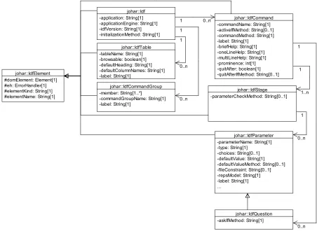
3.2 The Class Diagram of thejohar.idfPackage . . . 25
3.3 A sample annotated IDF for generating test cases . . . 28
3.4 Test Case 1 in TS 1 . . . 30
3.5 Test Case 2 in TS 1 . . . 31
3.6 Test Case 1 in TS 2 . . . 32
3.7 Test Case 2 in TS 2 . . . 33
3.8 Test Case 1 in TS 3 . . . 34
3.9 Test Case 2 in TS 3 . . . 35
3.10 Architecture of the Automated Testing Tool . . . 37
3.11 Error Log for Test Case 1 in TS 1. [No error is detected] . . . 38
3.12 Error Log for Test Case 1 in TS 2. [An error is detected] . . . 38
3.13 Summary Report of the tests . . . 39
4.1 The Main Panel ofStarGUI . . . 42
4.2 The Command Dialog Box ofStarGUI . . . 44
4.3 The Parameter Section of the Command Dialog Box . . . 45
4.4 The Question Dialog Box ofStarGUI . . . 45
4.5 The Help Box ofStarGUI [Top-Level State] . . . 46
4.6 The Help Box ofStarGUI [Command State] . . . 47
4.7 The Help Box ofStarGUI [Parameter/Question State] . . . 47
4.8 The Message Dialog Box ofStarGUI . . . 48
4.9 The Class Diagram showing the key components of Starand the relationship among them . . . 50
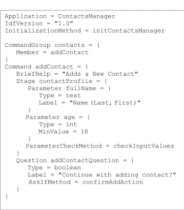
4.10 IDF for the Temperature Converter App . . . 52
4.11 The XML equivalent of the Temperature Converter App’s IDF . . . 53
4.14 Main Panel of the Temperature Converter App [TheStarMenu] . . . 55
4.15 The Command Dialog Box for the “Celsius to Fahrenheit” Command . . . 56
4.16 Text Display Area shows the conversion result . . . 56
4.17 Top-Level State of the Temperature Converter App’s Help Box . . . 57
4.18 Command State of the Temperature Converter App’s Help Box . . . 57
4.19 Parameter State of the Temperature Converter App’s Help Box . . . 57
4.20 The Question Dialog Box confirming user’s intent to exit the App . . . 58
4.21 Main Panel of the Appointment Calendar App . . . 59
4.22 Main Panel of the Appointment Calendar App [TheAppointmentMenu] . . . . 59
4.23 Command Dialog Box for the “Add Appointment” Command . . . 60
4.24 A notification and a new appointment are shown in the Text Display Area and Appointment table respectively . . . 60
4.25 Weeks table indicates the existence of three appointments . . . 60
4.26 Selecting the “Go To Date” Command . . . 61
4.27 The Command Dialog Box for the “Go To Date” Command . . . 61
4.28 Selecting an appointment from the Appointment table . . . 62
4.29 Cancelling the selected appointment via the “Cancel Appointment” Command . 62 4.30 Cancellation notification in the Text Display Area and deletion of appointment from the Appointment table . . . 62
4.31 Top-Level State of the Appointment Calendar App’s Help Box . . . 63
4.32 Selecting the Exit Command to terminate the Appointment Calendar App . . . 63
4.33 A Message Dialog Box notifying the user of a successful termination of the App 64 5.1 A red border acting as a visual cue for a widget that currently has focus . . . . 68
5.2 The Hotkeys Pop-up Table . . . 69
5.3 An input file containingGrupocommands for interacting with the Appointment Calendar App . . . 72
5.4 Grupo accepts a test case, executes it against the App Engine via Johar, and displays output information on Standard Output for a Tester’s perusal . . . 75
A.1 Example of IDF syntax. . . 85
A.2 Examples of camel-case translation. . . 103
List of Tables
2.1 An example of a blind user’s capability captured in the Knowledge Base . . . . 18
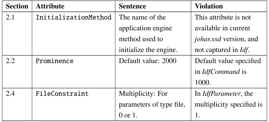
3.1 Some results of the review of Johar-related documents for consistency . . . 26
4.1 Outcome of reviewingStarSpecification documents in conjunction with the Interface Interpreter Specification document . . . 65
5.1 Prefix for each category of information displayed on the Standard Output . . . . 76
B.1 Bindings of Johar parameter types to Java types. . . 107
J.1 Keyboard shortcuts for the Menu Bar . . . 181
J.2 Keyboard shortcuts for the Text Display Area . . . 181
J.3 Keyboard shortcuts for the Table Area . . . 182
J.4 Keyboard shortcut for the Cancel, Previous, Next and OK buttons . . . 182
J.5 Keyboard shortcuts for the Parameter Section . . . 183
J.6 Keyboard shortcuts for buttons in the Repetition Section of a Parameter Section 184 J.7 Keyboard shortcuts for the Question Dialog Box . . . 184
J.8 Keyboard shortcuts for the Help Box buttons . . . 185
J.9 Keyboard shortcuts for the Top-Level State’s Commands table . . . 185
J.10 Keyboard shortcuts for the Command State’s Text Area . . . 186
J.11 Keyboard shortcuts for the Command State’s Parameters table . . . 186
J.12 Keyboard shortcuts for the Command State’s Questions table . . . 186
J.13 Keyboard shortcuts for the Parameter/Question State’s Text Area . . . 187
J.14 Keyboard shortcuts for the Boolean Widget . . . 187
J.15 Keyboard shortcuts for the Choice/TableEntry Widget . . . 188
J.16 Keyboard shortcuts for the Date Widget . . . 188
J.17 Keyboard shortcuts for the File Widget . . . 189
J.18 Keyboard shortcuts for the Number Widget . . . 189
J.19 Keyboard shortcuts for the Text Widget . . . 190
J.20 Keyboard shortcuts for the Time Widget . . . 190
J.21 Keyboard shortcut for the Message Dialog Box . . . 191
K.1 GrupoCommands . . . 193
K.2 Prefixes of output messages . . . 196
Appendix A Johar Interface Description File (IDF): Format Specification . . . 84
Appendix B Interface Interpreters (IntIs): Requirements Specification . . . 104
Appendix C Johar XML Schema Document . . . 111
Appendix D Report On The Review Of Johar-Related Documents . . . 118
Appendix E “Star” Interface Interpreter: Requirements Specification of the Star GUI . . 124
Appendix F “Star” Interface Interpreter: Requirements Specification (Behaviour) . . . . 131
Appendix G Some Source Code of “Star” Implementation . . . 141
Appendix H App Engine of the Temperature Converter App . . . 172
Appendix I Interface Description File (IDF) of the Appointment Calendar App . . . 175
Appendix J “StarX” Interface Interpreter: Requirements Specification of the StarX GUI . 180 Appendix K “Grupo” Interface Interpreter: Requirements Specification . . . 192
Appendix L “Grupo” Interface Interpreter: Requirements Specification (Behaviour) . . . 197
Chapter 1
Introduction
Accessibility in computing is concerned with the removal of barriers that exclude some group
of people from using the computer. Designing software applications for accessibility is concerned with making programs and functionality available to a variety of users, whether
disabled or non-disabled. Unfortunately, almost all software applications contain some
barriers to people with disabilities [1]. Although there are assistive technologies (such as
screen readers) to bridge this digital divide, many applications are incompatible with these
technologies since they were designed for non-disabled users. This situation may continue to
worsen, considering the increasing population growth of disabled people. For example,
approximately 56.7 million Americans (18.7% of the civilian noninstitutional population)
have some form of disability as at 2010, as opposed to the 54.4 million population in 2005 [2].
Moreover, the World Health Organization (WHO) estimated that 285 million people are
visually-impaired globally in 2010 (out of which 39 million are blind) [3], and the global population of blind people is expected to increase to 78 million by 2020 [4].
Furthermore, in order to make an application accessible, the interface through which a user
interacts with the application to undertake his or her tasks must be considered. This interface (popularly known as user interface) can be graphical, vocal or textual, but the decision about how it should be presented must be based on the ability of the user. For example, a blind user
cannot read commands and information presented in graphical or visual format (e.g. menus,
tables, buttons, icons, etc.); a deaf user cannot comprehend any information presented vocally
(i.e. speech output); a low vision user cannot read any text presented in small font or notice
a small control; a motor-impaired user will have difficulty controlling a pointer and clicking with the mouse; etc. Hence, an application becomes accessible if its user interface fits users’
abilities and needs.
Some research efforts have already been directed towards making applications accessible to disabled and non-disabled users. These efforts led to the development of assistive
technologies (such as screen readers for blind users [5][6][7], screen magnifiers for low-vision
users [8], pointing tools for motor-impaired users [9], speech-enabled systems for blind and
low-vision users [10]), accessibility APIs (used by assistive technologies and applications to
access interface components) [11][12][13], and personalized user interface generators which automatically generate user interfaces based on users’ ability or preferences [14][15][16].
Unfortunately, assistive technologies are not compatible with all applications, and the
generated user interfaces may not fit the ability and needs of every user.
Our determination to complement the efforts of other researchers in resolving accessibility issues led to the development of ourJohar framework [17], which facilitates the development of applications accessible to both disabled and non-disabled people.
1.1
The Johar Framework
“Johar” is a framework that facilitates the development of applications that can be used by both disabled and non-disabled users [17]. The Johar framework promotes the separable
interface theory [18] by providing a separation between the front-end user interface and the
application-specific logic. Thus, experienced user interface designers can focus on developing
user interfaces that fit the ability and needs of users, while application developers can focus on
implementing the underlying functionality or application-specific logic of applications.
In our work, the ability-based front-end interfaces are called Interface Interpreters, while
their designers are known as Interface Interpreter developers. The application-specific logic or
functionality implemented by application developers are called applications or apps. The Johar framework binds each Johar interface interpreter to each Johar app [17]. Thus,
improvements in interface interpreters automatically improve access to all applications, and
improved applications are accessible to all users [17]. This is in contrast to other efforts in accessible software development, in which improvements often help one group of users to
access one kind of application.
As shown in Figure 1.1, a user interacts with an app using anInterface Interpreter that is suitable. This interface interpreter first reads the Interface Description File(IDF) written by the app developer, and then communicates with theapplication enginethrough Johar.
1.1.1
Interface Interpreter (IntI)
The interface interpreter is the mediator between the user and a Johar app. An interface
1.1. TheJoharFramework 3
Interface
Interpreter
User
Johar
Written by
interface
IDF
Written by
application
developer
developer
interpreter
Application
Engine
Figure 1.1: Architectural Model of the Johar Framework [17]
users, etc.). Thus, in order to access the desired app, each user must select an interface
interpreter that suits his or her ability and needs (see Figure 1.2 and Figure 1.3). For example, a non-disabled user can select a graphical or WIMP1 interface interpreter; a blind user can select a speech-driven/sound-based interface interpreter; a motor-impaired user can select an interface interpreter that support certain interaction techniques depending on their dexterity
(e.g. scanning-based interaction, eye gaze, head gestures, voice-driven interaction,
mouse-driven interaction, keyboard-driven interaction etc.); and so on.
Interface interpreters interact with various input/output devices (e.g. keyboard, camera, speaker, microphone, GPS device etc.) to get input data from users, and to present output data
in a form that the user can perceive via their working senses (e.g. hearing, sight, etc.).
1.1.2
Application Engine
The application engine orapp enginecontains the application-specific logic, which is made up of various components and objects that perform series of computations on the input in order to
transform it to an output. The app engine is the core of any Johar app. The app engine receives
input data from the interface interpreter, and then performs computations on the data, thereby
producing an output which is sent to the interface interpreter. The output can be in form of table data or text. During computation, the app engine may access external resources, such as
1WIMP stands for Windows, Icons, Menus, and Pointers. The most prevalent of the graphical user interfaces
Figure 1.2: Each user can access all Johar apps via his or her selected Interface Interpreter [17]
databases, files, third-party APIs, etc.
1.1.3
Interface Description File (IDF)
The Johar IDF contains a high level description or definition of a user interface. Our approach
to defining interfaces is based on theIntent-based Interaction Model, presented in Figure 1.4. In this model, every interaction session between a user and a Johar app can be described as
a cycle which alternates between a phase in which the user specifies what they intend the
application to do (Intent Specification), and a phase in which the app does it (Application
Computation) [17]. This interaction cycle begins when an app is launched.
Whenever a user launches an app, the app engine may perform some initial computation
and presents initial data to the user. Afterwards, the user is required to specify his or her intent
depending on the task at hand. While specifying his or her intent, a user may browse the
initial data (e.g. table data), select data (e.g. select single or multiple rows in a table), select a
command (e.g. selecting a menu in a GUI or typing a command in a text-based/command-line interface), select parameters (which are inputs to a command), refine his or her intent by
providing additional parameters, and confirm his or her intent (e.g. by answering anare you sure question). Once the intent specification is fully completed, the app performs some computation (via the app engine). Thus, activities 1 and 2 are application-specific and
performed by the application engine, while activities 3, 4, and 5 take place at the
1.1. TheJoharFramework 5
Figure 1.3: Each app can be accessed by all users via their selected Interface Interpreters [17]
The IDF Format
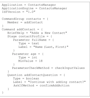
The objectives of any IDF are: (1) to describe the nature of an application and the functionality available to users; and (2) to describe the nature of the data that will be exchanged between the user and the application. In a bid to accomplish these objectives, the IDF is structured as a tree of attribute instances, where each attribute instance can have a
nameandvalue[17]. The attribute value can contain more attributes. Each attribute-value pair contributes towards achieving the objectives above. A brief description of some important
attributes of an IDF is given below. Appendix A of this thesis shows all the attributes and their
respective semantics and syntax.
• ApplicationEngine: This attribute specifies the class that contains the
application-specific logic of the app.
• Command: This attribute represents the basic top-level unit of user-application
interaction. ACommandrepresents a service or functionality provided by the app. It also
corresponds to a broad statement of intent the user can make. For example, in a
graphical Word Processor, the “Copy” menu item is a command; while in a Unix
terminal, “cp” is the equivalent command for “Copy”. The sub-attributes of Command
specify the app engine method that determines if a command is active, the help
Interface Interpreter
Intent confirmation, Intent refinement,
Parameter selection
Broad statement
of intent Data selection
Data browsing, computation
Application
presentation Data
5
1 2
3 4
App−Specific
Generic
Application Engine
Figure 1.4: The Intent-based Interaction Model [17]
engine method that performs the actual computation, label of the command, app engine
method that determines whether the app should quit after performing the computation,
and stages of the command (for wizard-style interaction).
• CommandGroup: This attribute represents a group of related commands. For example, in
a graphical text editor, the File menu is a command group. Its sub-attributes specify the
label of the command group, and each command in the group.
• Table: This attribute represents a list of similar data entities (i.e. table) presented to the
user by the app engine. Its sub-attributes specify the default table header, default column
names, and a value stating whether the table is browsable or not. A browsable table is
visible to the user, and rows can be selected from it.
• Parameter: This represents a piece of data which comes from the user and is relevant
to the Command, such as an integer, floating-point number or string. It has many
sub-attributes, but the important sub-attribute is theType, which specifies the parameter type.
The valid types are int, float, boolean, text, file, tableEntry, choice, date,
and timeOfDay. A Parameterof type tableEntry must contain theSourceTable
attribute.
• Question: This represents a question that should be asked of the user. The
sub-attributes of Question are similar to most of the sub-attributes of Parameter,
except that Question has a sub-attribute that specifies the app engine method which
determines whether the question should be asked or not. Questions can be used to
1.2. ThesisContribution 7
The IDF is written in a domain-specific language which is more concise than XML.
However, it is internally converted to XML during processing; thus, no technical skill is
required (from an app developer) to write a complete IDF for an app.
1.1.4
Software Architecture of Johar
The current Johar framework is implemented in Java, and it consists of two main packages
(johar.gem and johar.idf). The johar.gem package contains several classes that work
together to ensure smooth dialogue between the interface interpreter and the application engine
(such as facilitating exchange of data between them, and also invoking appropriate methods in
the application engine to handle users’ requests). Thejohar.idfprovides APIs that are called
by the interface interpreter to access the content (i.e. attributes and values) of an IDF.
Figure 1.5 shows the software architecture of the Johar framework. Although we hope to
port Johar to other platforms in the future, we expect that the architecture will remain very
similar.
1.2
Thesis Contribution
The overall goal of this thesis is to assure the quality of Johar, and to do so in a way that
allows us to reflect and report on our quantitative and qualitative observations. To achieve
this goal, we performed a comprehensive review of the entire Johar project so as to detect and
correct inconsistencies, omissions, irrelevances, and other loopholes that can hinder successful
deployment of Johar. We also implemented a complex interface interpreter and designed two additional interface interpreters. We can never say that any program is completely free of bugs,
or that design documents are of the maximum quality. However, we believe that the result of
our work is a set of documents and a working interface interpreter implementation that are, to
the best of our knowledge, complete, internally consistent, and consistent with each other.
We started work with the review of Johar’s components, which are the johar.gem and
johar.idfpackages. We discovered that thejohar.idfpackage is poorly structured because
only one class performs the overall function of the package. This kind of structure is bug-prone,
encourages code duplication, and prevents code reuse. We addressed this issue by restructuring
thejohar.idfpackage into a suite of specialized and interrelated classes.
The next phase of our quality assurance process involves comparing four documents for
consistency. The documents are: IDF Format Specification document2, XML Schema
johar.gem
Convey commands, parameters
and question responses
Extract text to display
Display text
Interface
Interpreter
Application
Engine
Browse and select table rows
Elicit commands, parameters
and question responses
IDF
Read
User
Extract table data
Display table data
Supply text to display
Supply and modify table data
Extract command, parameter
and question information
Figure 1.5: Software Architecture of the Johar Framework [17]
document3, the Interface Interpreter Specification document4, and the johar.idf package. The outcome of this review process revealed some discrepancies. We addressed these
discrepancies by making appropriate changes to these documents and their dependencies.
Furthermore, we decided to build a test infrastructure for IDFs, since they are critical to the
smooth running of interface interpreters. The test infrastructure determines whether all IDF
attributes are captured by the XML Schema andjohar.idfpackage. It also verifies whether
the XML Schema correctly validates an IDF, and whether all errors in an IDF are caught and reported.
Furthermore, since we have modified Johar in the course of our quality assurance activity,
we needed to test the practicability of the framework by developing and running an interface
interpreter and apps. Thus, we designed a new interface interpreter, called Star, which
1.3. ThesisOutline 9
provides a graphical user interface (GUI) through which users can access any Johar app. The
design documents of Star describe both the look-and-feel and behaviour of Star. We then reviewed these design documents and the Interface Interpreter Specification document for
consistency. After completing the review process and resolving inconsistencies and ambiguities, we implemented and testedStar. Also, we demonstrated the usage ofStar with an app.
In the last phase of our work, we wrote design documents for two future interface interpreters - StarX and Grupo. The StarX interface interpreter extends Star by providing keyboard shortcuts through which users (especially users with limited hand use) navigate the
entire graphical user interface. Grupo is a “batch-mode” interface interpreter that provides commands through which users carry out their tasks.
Finally, in the near future, we hope to release the first version of Johar as open source;
and we expect researchers, experienced interface designers, and application developers around
the world to explore Johar, and to build interface interpreters and apps on top of it. Thus, in
not so distant future, we would have formed Johar interface interpreter and app developers community, as well as users forum that will serve as a platform on which Johar developers brainstorm, and on which app users share their views and experiences.
1.3
Thesis Outline
Chapter 2 contains the background and related work. Chapter 3 contains a detailed description
of the quality assurance processes, and the resulting effects on the internal structure of Johar and its dependencies. Chapter 4 contains the specification, design and implementation details
of our new interface interpreter for graphical interfaces, calledStar. This chapter also contains a description of how we assure the quality ofStar, and how we usedStarto access (and interact with) a Johar app. Chapter 5 contains the specification of two other interface interpreters,
Background and Related Work
The background of this thesis is drawn from the answers to the following questions: What are
the technologies currently used by disabled people to access applications? What techniques
are adopted by these technologies to provide accessibility? Section 2.1 and Section 2.2 provide
a summary of the research conducted to find answers to these questions.
Our research findings summarized in Sections 2.1 and 2.2 revealed the vital role a user
interface plays in making an application accessible. This revelation led to the following
questions: What is the general structure or model of a user interface? How can a user interface
be designed to support users with diverse abilities? We conducted further research in order to
answer these questions. Section 2.3 presents a summary of our findings for the first question, while Sections 2.4 and 2.5 are for the second question.
2.1
Assistive Technologies
People with disabilities - such as visual impairment, blindness, and motor impairment - can operate computers to perform their tasks via assistive technologies.
For computer users with low vision, the prominent assistive technology is screen
enlargement software, such as ZoomText Magnifier [20] and MAGic [8], which increase the
size of controls and texts on the screen so they can be clearly visible to users. Screen readers assist blind users in using applications on computers. Screen readers basically read computer
screens and speak the text contents [21]. In other words, screen readers have the capability to
analyze user interface components (menus, message/dialog boxes, text containers, etc.) and produce the speech output of their contents [22]. Most screen readers support Braille displays.
Some of the prominent screen readers are Job Access With Speech (JAWS) [5], Non-Visual
Desktop Access (NVDA) [6], Windows Eyes [7], ZoomText Reader [20], Narrator [23],
2.1. AssistiveTechnologies 11
VoiceOver [24], Linux Screen Reader [25], and Orca [26]. These screen readers run on
specific platforms; for example, the first five screen readers above run on Windows operating
systems, VoiceOver runs on Apple-based operating systems (Mac OS X, iOS), while Linux
Screen Reader and Orca run on GNOME-compliant operating systems (OpenSolaris, Ubuntu, etc.). JAWS, NVDA and VoiceOver are the commonly-used screen readers [27].
Assistive technologies for motor-impaired users also exist. Punyabukkana et al. [10]
designed a sound-based input system that allow users to traverse, select, and activate commands in Windows GUI just by humming and making fricative sounds. The hum sound
initiates traversal in a direction (e.g. moving from one menu to the other in the right
direction), while the fricative sound stops the traversal and activates the selected command.
The pitch of the hum sound is used to determine the direction of the traversal. These two
sounds were also used in controlling the cursor to perform point-and-click tasks (e.g. clicking
a button to launch an application or save a document) [28]. The hum sound controls the
pointer, while the fricative sound clicks the control (e.g. button or icon) at the location of the
pointer. Another assistive technology for the motor-impaired is ceCursor [9] which uses
eye-gaze tracker in controlling a screen pointer on Windows. The user can move the cursor in one of four directions (up, down, left, right) by gazing in that direction, and clicking of
interface controls is achieved whenever the user looks at the centre of the cursor for 1 second.
Biswas et al. presented new systems to assist computer users with severe motor impairments
[29][30]. The first is the cluster scanning system which identifies potential targets (e.g. buttons, icons, menus, and other widgets) on the screen and then groups them into clusters based on
their locations. The user selects the cluster containing the target using a push button switch,
and then the system iteratively divides the selected cluster into smaller clusters, until only one
cluster remains (which contains the target). The second system combines eye-gaze tracking
and scanning techniques to achieve greater efficacy. The eye-gaze tracker moves the pointer closer to (or on) the target, and then the system switches to the 8-directional scanning mode
(after a key press from the user) to focus and click on the target.
Although these assistive technologies have helped computer users with impairments to
interact with applications on computers, most high-quality commercially-available screen
readers and magnifiers are expensive, as well as eye-gaze trackers and switches (which are not
widely available). Also, most screen readers do not provide access to all applications, since
2.2
Accessibility APIs
Accessibility APIs (Application Programming Interfaces) mediate between assistive
technologies and applications. As shown in Figure 2.1, a user interacts with an application via an assistive technology, which in turn relies on an accessibility API to perform its function.
Accessibility APIs enable assistive technologies to successfully identify, access, and
manipulate elements of an application’s user interface.
Microsoft developed two accessibility APIs that allow assistive technologies to access applications running on Windows operating systems. The first API is called Microsoft Active
Accessibility (MSAA) [11], which is based on the Component Object Model (COM)
technology. It provides API elements which contain methods for exposing information about
user interface elements. Thus, assistive technologies (via the OLEACC library) can interact
with and retrieve the content of standard or common interface controls for any Windows
application. The IAccessible interface of MSAA allows applications to further expose
information about interface elements that are not available to assistive technologies by default
(e.g. custom controls and windowless elements). Assistive technologies are notified (via
WinEventsor Windows Events) of changes in interface elements. They retrieve the contents
of (and other information about) interface elements through the properties exposed to them
(e.g. Name, Role, Location, Value, Description, Help, etc.), and can also navigate the tree of
interface elements (i.e. object model) in order to understand the structure of the user interface.
An example of a screen reader using MSAA is JAWS [5].
Assistive Technology
Accessibility API
(MSAA, IAccessible2, AT-SPI, etc.) Application
User
Figure 2.1: Relationship between Assistive Technologies, Accessibility APIs, and Applications
The latest API developed by Microsoft is UI Automation [12]. UI Automation offers support for new user interface elements, exposes a richer set of properties and control patterns
for UI elements, offers flexibility in navigating the object model (via scoping and filtering), and allows application developers to define custom control patterns, properties, and events.
Another post-MSAA API is IAccessible2 [13], which supports rich-text controls, Web 2.0
technologies, tables, and spreadsheets. This API is useful for rich document applications, such
as Word Processors, Spreadsheet packages, Web browsers using AJAX and DHTML, and so
2.3. UserInterfaceArchitecturalModels 13
Other accessibility APIs are the ATK (Accessibility Toolkit) and AT-SPI (Assistive
Technology Service Provider Interface) [32] which provide access to both GNOME and
non-GNOME based applications on Unix platforms; OS X Accessibility Protocol [33] which
supports applications on Mac OS X; and the Java Accessibility API
(javax.accessibility) [34] which support Java applications.
Accessibility APIs are not capable of exposing the underlying functionality of applications
to assistive technologies. Hence, users with disabilities, especially blind users, may experience difficulty building accurate mental models of an application since information collected by screen readers (for instance) at the interface level might not be sufficient to understand what the application is doing or can do. Moreover, developers, who have designed their GUIs mostly
for non-disabled users, will need to expend extra development cost and effort in making their custom GUI controls accessible.
2.3
User Interface Architectural Models
Earlier methods of system development require that the user interface and the system’s
functionality be managed in the same component. However, the resulting effect of this approach is the production of systems that resist modification and present difficulty in providing for human factors [35]. The panacea to this problem is postulated to be Separable
Interface Theory, which promotes the separation of the user interface from the functional
aspects of a system [18]. This theory has become a building block on which systems are
developed.
One of the most influential models that promote separable interface theory is the Seeheim
model [36]. As shown in Figure 2.2, the Seeheim model has three components: presentation
component, dialogue control, and the application interface model. The presentation component generates the physical user interface that the user interacts with. The presentation component
interacts with the input/output devices to receive input data from users and to display output data to users. The presentation component sends input data to (and receives output data from)
the application interface model via the dialogue control. In other words, data representing a
user’s requests are channeled through the dialogue control to the appropriate procedure in the
application program, which performs necessary computations on the data, and then sends the
results to the presentation component through the dialogue control. The application interface
model represents the application, including the data objects, procedures, and constraints. These
constraints are restrictions on the input supplied by users.
Presentation Component
Dialogue Control
Application Interface Model
USER
Figure 2.2: The Seeheim Model [36]
The goal of developing the Arch model is to generate user interfaces that manage the
interaction between two externally-provided components - application domain functionality
and the UI toolkits [37]. Five components make up the Arch model, with each serving a
different purpose (as shown in Figure 2.3). The presentation component generates the virtual representation of the user interface (using presentation objects), while the interaction toolkit
component generates the physical interface (using interaction objects supplied by UI Toolkit
packages or software, e.g. Java Swing GUI toolkit, Google maps driver, speech drivers, etc.).
The interaction objects in the physical interface correspond to the presentation objects in the
virtual interface. Application-specific functions (including managing domain data) are handled by both the domain-specific and domain-adaptor components through the domain
objects. The domain-adaptor component provides services related to the presentation of
information, while the domain-specific components perform operations or computations that
do not relate to the user interface. The dialogue component coordinates the interaction
between the presentation component and the domain-adaptor component, in terms of data
exchange and sequencing of tasks.
Other interface architectural models that complement the Seeheim model are
Model-View-Controller (MVC) [38] and Passive-View-Command (PVC) [39].
Our work fits the separable interface theory, since the front-end interface interpreters are
separated from the application engine, and the communication between both are facilitated by
the Johar framework.
Alonso et al. [40] aimed to develop a user interface model for the blind. The model is built
upon six human-computer interface models by supplementing each of them with additional
requirements for blind users. The models are task model, domain model, dialog model,
presentation model, platform model, and user model [40]. The summary of each model’s
additional requirements for the blind are: (1) the tasks described in the task model should fit
2.4. UserInterfaceDescriptionLanguages 15
Figure 2.3: The Arch Model [37]
components that conform to 1-dimensional navigation and also provide speech and Braille
output to support user interaction; (3) the dialog model should support keyboard or equivalent
as interaction medium for input, while output messages should be received via speech
synthesizers or Braille displays; (4) the presentation model should also define the speech and
Braille output for each interface object, as well as the different levels of user experience; (5) the platform model should define the capabilities of speech and Braille output provided by
standard APIs [40]; and (6) the user model should include certain configuration parameters,
such as the speech parameters, Braille parameters, and detail level of output messages [40].
Our work complements that of Alonso et al, since their model can be used to build interface
interpreters for the blind.
2.4
User Interface Description Languages
User interface management systems require a description of the user interfaces to be implemented in order to automatically (or semi-automatically) generate the interfaces [36].
This description of user interfaces can be achieved via user interface description languages
(UIDLs). UIDLs allows interface designers to describe a user interface using high-level
constructs or syntax which abstract away implementation details as well as details of input
and output devices [41]. Most UIDLs are XML-compliant languages (in order to take
interface generators to produce desired user interface for target platforms.
We studied four UIDLs, namely UIML (User Interface Markup Language) [42], XIML
(eXtensible Interface Markup Language) [43], USIXML (USer Interface eXtensible Markup
Language) [44], and AUIML (Abstract User Interface Markup Language) [45] in order to
understand their approach to specifying user interfaces. In UIML, user interface elements (or
parts) and their associated content (e.g. text, images, sound, etc.), presentation style (e.g.
layout, colour, font, size, etc.) and interaction behaviour are represented using customized tags and vocabularies. The vocabularies are supplied by the User Interface toolkit(s) (e.g.
Voice toolkit - for voice enabled interfaces, HTML toolkit - for web interfaces, Java
AWT/Swing - for graphical user interfaces, etc.) required for presentation or rendering. UIML can also specify the connection of the user interface to the application logic.
Unlike UIML, USIXML describes a user interface in four levels of abstractions depending
on the context of use [44]. The levels in order of abstraction (high to low) are tasks and concepts,abstract user interface (AUI),concrete user interface (CUI), andfinal user interface (FUI). The tasks and concepts level views a user interface as composed of interrelated tasks and the domain (i.e. representation of real-world objects) in which the tasks are undertaken.
The AUI level views a user interface as composed of interrelated abstract interaction objects,
which can be grouped into various interaction spaces (i.e. containers). The CUI level describes
the appearance (using concrete interaction objects which are closer to the physical widgets)
and user’s modality of interaction (graphical or auditory) with the interface. The FUI level presents the physical user interface shown to the user.
Similar to USIXML is XIML, which groups user interface components into abstract and
concrete. The abstract components are task, domain, and user. The task and domain
components are similar totasks and conceptsin USIXML, while theusercomponent defines the characteristics of each user group or individual user. Furthermore, the concrete
components in XIML are dialog and presentation, which are similar to the concrete user interface in USIXML. The presentation component describes the appearance of the user interface, while the dialog component describes the modality of interaction. Like USIXML,
the relationship between interface elements within each component or across components is
also captured. Unlike USIXML, XIML does not describe the platform-dependent and
toolkit-dependent representation of the final interface shown to the user.
Finally, IBM developed AUIML for internal use with a view to defining user interfaces
based on the purpose or intent of interaction, rather than appearance [45]. But AUIML, like
other languages mentioned above, describes the look or layout of the user interface using
2.5. PersonalizedUserInterfaceGenerators 17
specifies actions that associate application routines with these objects [47].
2.5
Personalized User Interface Generators
Personalized User Interface Generators are developed by researchers to automatically generate
user interfaces tailored to individual users’ ability, preferences, and needs. The fundamental
requirement for all user interface generators is an abstract description of the interface they need
to generate, and this is achievable using any of the available UIDLs. Some of the relevant user
interface generators we studied are SUPPLE [14], SUPPLE++[15], and EGOKI [16].
SUPPLE and SUPPLE++ generate user interfaces to support motor-impaired users in performing point-and-click tasks (i.e. tasks involving clicking, dragging, pointing, list
selection, etc.). SUPPLE relies on an interface specification, device model, usage model, and a cost function in order to generate the desired user interface. The interface specification
describes the types of data (including associated constraints) to be exchanged between the
application and the user, as well as action types (which are useful for invoking application
methods at run-time). The device model is a representation of available widgets, as well as device-specific constraints. The usage modelrepresents usage patterns or traces generated as the user interacts with the user interface. These usage patterns are used by SUPPLE in
determining the prominence or priority of interface widgets, during the layout process or
customization. The cost function determines the presentation style and quality of the user interface. For SUPPLE, the model of user preferences is used as the cost function. In order to
obtain the model of user preferences, each user interacts with a preference-elicitation tool
(developed by the authors, called ARNAULD) which asks the user to choose from queries
showing two functionally equivalent but different user interface fragments (for example, a user may be asked to choose between list box and combo box, radio buttons and combo box, check boxes and list box, etc.). Alternatively, the ARNAULD system may show the user a
preview of how the user interface for an application will look when generated; afterwards, the
user is asked to suggest improvements to this user interface. The user is also allowed to
customize the user interface at run-time (such as re-arranging widgets or removing widgets).
The authors of SUPPLE conducted experiments by generating user interfaces for
non-disabled users, motor-impaired users, and users with slight vision impairment [14][48].
Similar to SUPPLE is SUPPLE++, which personalizes interfaces based on users’ motor abilities, instead of user preferences. To achieve this, SUPPLE++ has a built-in ABILITY MODELER, which builds a model of users’ motor abilities after observing their performance
used as the cost function to generate the ability-based user interface [15] [49].
EGOKI generates user interfaces that provide access to ubiquitous services. It requires a
UIML document, and the target user’s capability as inputs. The UIML document specifies the
structure, style, content, and behaviour of interface elements. Moreover, the UIML document
contains all functionality provided by the service, as well as the media types (i.e. audio, video,
text, image, etc.) for the resources supplied by the user interface toolkit. The service
functionality and media types are assigned priorities in order to guide selection of interface resources or widgets during layout. Furthermore, EGOKI maintains a knowledge base
containing information about each media type and its associated resources and possible
adaptations, based on user capabilities. Each user capability is formed by combining each
interaction modality1 and each capability level2. For instance, Table 2.1 shows an example of the capability of blind users, and the corresponding media type, resources, and adaptations.
Modality
Media Resource Adaptation
Vision Auditory Speech Motor Cognitive Type
Null High High High High
Audio Text
Navigation Support, Video Text
Image Text Text Header
Text Text
Table 2.1: An example of a blind user’s capability captured in the Knowledge Base
Furthermore, the EGOKI system begins the user interface generation process by selecting
the appropriate resources and adaptations (using the target user’s capability to search the
knowledge base for a match) for each functionality provided by the service. It then transforms
the abstract user interface (described in the UIML document) into the final user interface, after
confirming that the selected resources are available in the UI toolkit specified in the UIML
document. The final user interface generated is in XHTML format, which can easily be
rendered for display on target devices. Any extra adaptation or customization can be applied to the user interface using CSS (Cascading Style Sheets).
Our work complements those of SUPPLE and SUPPLE++, since the resources, such as those used in achieving automatic and user-driven customization of interface elements, can be incorporated into graphical interface interpreters. Finally, in contrast to our work, EGOKI’s
final user interface can only be rendered as a Web interface on target devices, which may not
2.6. Conclusion 19
be suitable for blind users. Even though screen readers are available for web interfaces, their
verbosity while reading screen contents can slow down blind users, thereby increasing task
completion time.
2.6
Conclusion
From our research findings presented above, the following shortcomings are evident. The Johar
framework is aimed at addressing these issues.
(1) Assistive Technologies are not compatible with all applications, and also not suitable for
all disabled users.
(2) Most interface description languages require developers to describe specific patterns of
user interactions (i.e. structure and appearance of interface elements) in their user
interface definitions. This hinders accessibility, since some group of users may prefer some other interface structure or appearance not captured in these definitions. For
example, some blind users may prefer a user interface that allows them to issue simple
text commands to locate and open existing files in a Text Editor, instead of using screen
readers to navigate a user interface composed of a dialog box and containers (for listing
drives, directories, and files). This is due to the fact that screen readers will spend a lot
of time reading the containers and their contents (the drives, directories, and files), and
any other widgets in the dialog box. Certainly, this process will cause frustration for
blind users, since it will hinder them from performing their intended tasks quickly.
(3) It is very difficult to develop user interface generators that personalize user interfaces for all users, considering the wide range of user abilities and the dynamism involved.
Users’ abilities change and new abilities are created with time; thus, the development
(and maintenance) cost and effort required to keep modifying these interface generators to cater for new or changes in abilities will be very difficult to bear.
The first and third shortcomings are addressed by developing interface interpreters that fit
the abilities and needs of a variety of user groups (such as non-disabled users, blind users,
motor-impaired users, low-vision users, deaf users, and so on). The second issue is addressed
with our Interface Description File (IDF) which is not tied to any specific user interaction
Quality Assurance on Johar
In this chapter, we extensively discuss our quality assurance process targeted towards the
detection and correction of inconsistencies, omissions, irrelevances, and other loopholes that
could hinder successful deployment of Johar.
The quality assurance process is aimed at improving the two core components of Johar
(i.e.johar.gemandjohar.idf), as well as detecting and correcting flaws in the IDF Format
Specification document, IDF’s XML Schema document, and the Interface Interpreter
Specification document, which are all critical to the success of the Johar project. Furthermore,
error detection and reporting tests were carried out on IDFs via our automated testing tool
developed for this purpose.
3.1
Review and Redesign of Johar Components
There are two main components of Johar: johar.gem and johar.idf (see Section 1.1.4).
Since the current Johar implementation is in Java, these components are packages containing
several interrelated classes that facilitate the development of interface interpreters and apps.
3.1.1
The
johar.gem
package
Thejohar.gempackage is responsible for the following activities:
(1) Invoking methods in the app engine;
(2) Communicating input data (i.e. commands, parameter values, and question responses
elicited by the user via the interface interpreter) to the app engine, and also
communicating output data from the app engine to the interface interpreter.
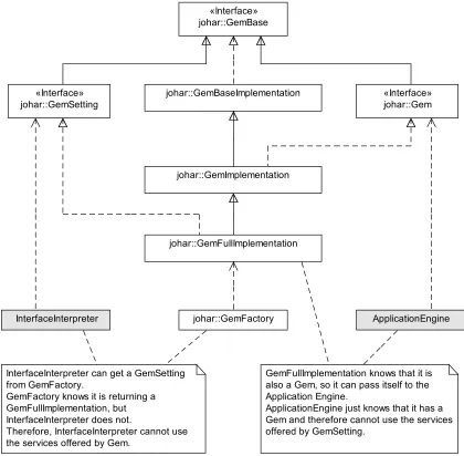
Figure 3.1 shows all the classes in the johar.gempackage. GemSetting interfaces with interface interpreters, while Gem interfaces with app engines. In other words, an interface
3.1. Review andRedesign ofJoharComponents 21
interpreter sends user inputs to and receives output data from an app engine via GemSetting, while the app engine receives user inputs from and sends output data to the interface interpreter
viaGem.
johar::GemBaseImplementation
johar::GemImplementation «Interface» johar::GemBase
«Interface» johar::GemSetting
ApplicationEngine johar::GemFullImplementation
InterfaceInterpreter
GemFullImplementation knows that it is also a Gem, so it can pass itself to the Application Engine.
ApplicationEngine just knows that it has a Gem and therefore cannot use the services offered by GemSetting.
johar::GemFactory
«Interface» johar::Gem
InterfaceInterpreter can get a GemSetting from GemFactory.
GemFactory knows it is returning a GemFullImplementation, but InterfaceInterpreter does not.
Therefore, InterfaceInterpreter cannot use the services offered by Gem.
Figure 3.1: The Class Diagram of thejohar.gemPackage
The GemFullImplementation andGemImplementation are the brains behind the activities of GemSetting and Gem respectively. Specifically, GemSetting forwards the commands, parameter values, and question responses it received from the interface interpreter to
GemFullImplementation, which then invokes the appropriate method in the app engine for computation to begin, and also makes the parameter values and question responses available
makes the data accessible to GemFullImplementation for use by the interface interpreter throughGemSetting.
The Review Process
Our review of the 2009 version of johar.gempackage is aimed at determining whether the
two activities outlined in subsection 3.1.1 are effectively carried out by the package. To achieve this aim, we reviewed the functionality of all the classes in this package.
The outcome of our review revealed the critical shortcomings outlined below. Afterwards, we explain the cause and effect of these shortcomings on the Johar project.
(1) GemSettingdid not have the feature needed to automatically initialize all tables that are supposed to hold table data coming from the app engine, when an interface interpreter is
started by the user.
(2) GemSettingdid not have the feature needed to automatically validate all the app engine methods used in an IDF against the actual methods in the app engine.
(3) GemFullImplementationwas passive in determining which app engine method to invoke or trigger for computation to begin. It relies onGemSettingto provide the method name, which meansGemSettingmust get this information from the interface interpreter.
(4) GemFullImplementationdid not validate each parameter value received fromGemSetting
against the parameter type in the IDF. This means that GemFullImplementation could accept an integer value for a parameter declared asfloatin the IDF.
These shortcomings occurred because the 2009 version of johar.gem package did not
access the IDF at all. As stated in chapter 1, the IDF provides information about the nature
of an app (such as app name, name of app engine, app engine methods that perform specific functions, etc.), functionality or features available to users (such as commands, help facility,
table browsing, parameter selection, answering questions, etc.), and the type of data to be
exchanged between interface interpreters and the app (such as textual data, boolean values,
integer values, files, calendar date and time, etc.). Unfortunately, as important as these pieces
of information are, the 2009 version of johar.gempackage had no knowledge of them.
The major effect or consequence of this knowledge gap is that the interface interpreter, which has access to the content of an IDF, must bridge the gap by initializing all tables at
launch time, validating all app engine methods used in the IDF (which can only be achieved by
![Figure 1.1: Architectural Model of the Johar Framework [17]](https://thumb-us.123doks.com/thumbv2/123dok_us/7792928.1291915/17.612.162.467.74.285/figure-architectural-model-johar-framework.webp)
![Figure 1.2: Each user can access all Johar apps via his or her selected Interface Interpreter [17]](https://thumb-us.123doks.com/thumbv2/123dok_us/7792928.1291915/18.612.142.453.69.292/figure-user-access-johar-apps-selected-interface-interpreter.webp)
![Figure 1.3: Each app can be accessed by all users via their selected Interface Interpreters [17]](https://thumb-us.123doks.com/thumbv2/123dok_us/7792928.1291915/19.612.160.471.72.287/figure-app-accessed-users-selected-interface-interpreters.webp)
![Figure 1.5: Software Architecture of the Johar Framework [17]](https://thumb-us.123doks.com/thumbv2/123dok_us/7792928.1291915/22.612.130.489.72.432/figure-software-architecture-johar-framework.webp)
![Figure 2.3: The Arch Model [37]](https://thumb-us.123doks.com/thumbv2/123dok_us/7792928.1291915/29.612.131.499.73.303/figure-the-arch-model.webp)