ISSN(Online): 2319-8753
ISSN (Print): 2347-6710
I
nternational
J
ournal of
I
nnovative
R
esearch in
S
cience,
E
ngineering and
T
echnology
(An ISO 3297: 2007 Certified Organization)
Vol. 4, Issue 6, June 2015
System Design and Simulation
using(OptiSystem 7.0) for Performance
Characterization of the Free Space Optical
Communication System
Dr.Shehab A. Kadhim1 Abd Allah J. Shakir 2 Dr. Akram N. Mohammad3 Nadia F. Mohammad4
Ministry of Science and Technology, Iraq1,4
Dept. of Applied Science, Al-Technologia University, Iraq 2,3
ABSTRACT : Free space optical (FSO) communication has emerged as a viable technology for broadband wireless applications which offers the potential of high bandwidth capacity over unlicensed optical wavelengths. This research is focusing on FSO system designs and simulation study using a mathematical and computational program based on mathematical relationships of weather factors and their impact on the movement of the beam to evaluate the performance of Free Space Optical communication systems by study of the impact of weather factors affecting the transmission of laser beam carries the information within different ranges. The laboratory-measured data and the data obtained from the Iraqi Meteorological website (visibility) are used in calculations. Processed data and obtained results were identical to scientific publications and the results could be adopted as inputs for the preparation of an advanced computer course where results have been compared with some scientific software (optiSystem 7.0) which is a program for optical communication systems design and evaluation and the results were identical. This research considering the first step to create a scientific base for optical and electro-optical designs operating in communication field and with self-help efforts.
KEYWORDS : (FSO)communication system, atmosphere attenuation, OptiSystem 7.0 software I. INTRODUCTION
Free Space Optical (FSO) communication or Optical wireless communication(OWC) has emerged as a viable technology for next generation broadband wireless applications in different areas of the long and short haul communications space from links of inter satellite to links of inter building. In applying wireless infrared communication, non-directed links, which do not require precise alignment between transmitter and receiver are desirable. They can be categorized as either line-of-sight (LOS) or diffuse links. LOS links require an unobstructed path for reliable communication, whereas diffuse links rely on multiple optical paths from surface reflections. On the other hand, FSO communication usually involves directed LOS and point-to-point laser links from transmitter to receiver through the atmosphere. FSO communication over few kilometer distances has been demonstrated at multi-Gbps data rates [2].
ISSN(Online): 2319-8753
ISSN (Print): 2347-6710
I
nternational
J
ournal of
I
nnovative
R
esearch in
S
cience,
E
ngineering and
T
echnology
(An ISO 3297: 2007 Certified Organization)
Vol. 4, Issue 6, June 2015
II. FREE SPACE OPTICAL COMMUNICATION SYSTEMS
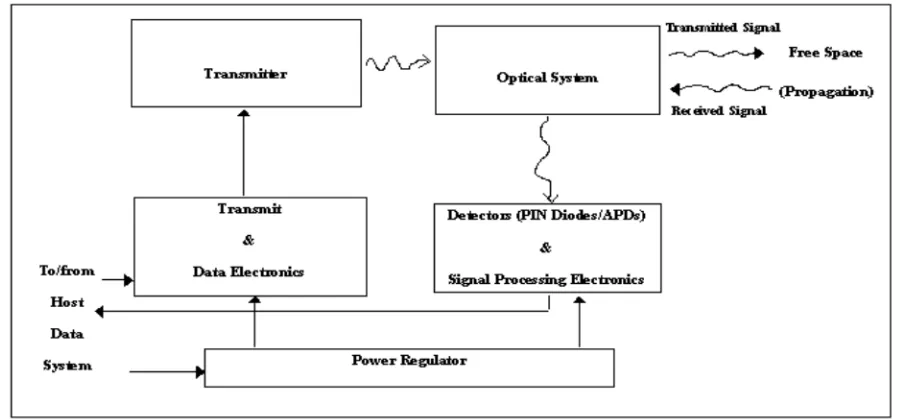
The major subsystems in an FSO communication system are illustrated in Fig. 1.1. A source producing data input is to be transmitted to a remote destination. This source has its output modulated onto an optical carrier; typically laser, which is then transmitted as an optical field through the atmospheric channel. The important aspects of the optical transmitter system are size, power, and beam quality, which determine laser intensity and minimum divergence obtainable from the system. At the receiver, the field is optically collected and detected, generally in the presence of noise interference, signal distortion, and background radiation. On the receiver side, important features are the aperture size and the f/-number, which determine the amount of the collected light and the detector field-of-view (FOV).
The modulation of the source data onto the electromagnetic wave carrier generally takes place in three different ways: amplitude modulation (AM), frequency modulation (FM), or phase modulation (PM), each of which can be theoretically implemented at any frequency. For an optical wave, another modulation scheme is also often used, namely intensity modulation (IM). Intensity is defined as flow energy per unit area per unit time expressed in W/m2 , and is proportional to the square of the fields amplitude. The light fields from laser sources then pass beam forming optics to produce a collimated beam. This practice is equivalent to providing antenna gain in RF systems.[5]
Figure 1.1: Block diagram of FSO communication system
.
There are two basic types of optical receivers: non-coherent receivers and coherent receivers. Non-coherent receivers directly detect the instantaneous power of the collected optical field as it arrives at the receivers, thus are often called direct or power detection receivers. These receivers represent the simplest type of implementation and can be used whenever the transmitted information occurs in the power variation (i.e. IM) of the optical field. Coherent receivers, better known as heterodyne receivers, optically mix a locally generated light wave field with the received field, and the combined wave is photo detected. These receivers are used when information is modulated onto the optical carrier using AM, FM, or PM, and are essential for FM or PM detection.
ISSN(Online): 2319-8753
ISSN (Print): 2347-6710
I
nternational
J
ournal of
I
nnovative
R
esearch in
S
cience,
E
ngineering and
T
echnology
(An ISO 3297: 2007 Certified Organization)
Vol. 4, Issue 6, June 2015
counting process at the photo detector. The thermal noise can be modeled as additive white Gaussian noise (AWGN), whose spectral level is directly proportional to the receiver temperature.[6]
III. ATMOSPHERIC OPTICAL CHANNEL
In FSO communication links, absorption of the beam by the atmosphere can be important, especially in adverse weather conditions of fog, snow, heavy rain, or obscuration. The combined effects of direct absorption and scattering of laser light can be described by a single path-dependent attenuation coefficient α(z).
The power received at the receiver can easily be calculated for links without significant turbulence effects. The received power PR for a receiver with receiver area A, range L, and beam divergence angle θ varies as [7]
Where PT is the transmitted power and α in this case is a constant value averaged over the propagation path L.
The received power can be increased by increasing the transmitter power, the receiver area, or by reducing the beam divergence of the transmitter beam, which must be not below diffraction limited. For FSO systems with the transmitted optical power of 10mW, beam divergence of 1 mrad, and a receiver diameter of 100 mm, the received power is still exponentially dependent on the atmospheric attenuation coefficient, as illustrated in Fig. 1.2. For a typical receiver sensitivity of -35 dBm, only an operational range less than 300 m can be achieved under heavy obscuration conditions. Even under light obscuration conditions, the link margin is reduced quite significantly compared with clear air conditions.
When turbulence effects are included, the effects of the atmosphere are in a sense more subtle. This optical turbulence is caused almost exclusively by temperature variations in the atmosphere, resulting in random variations of refractive index. An optical wave propagating through the atmospheric turbulence will experience random amplitude and phase fluctuations, which will generate a number of effects: breakup of the beam into distinct patches of fluctuating illumination, the wonder of the centroid of the beam, and increase in the beam width over the expected diffraction limit. For long links, the problems presented by atmospheric turbulence are quite severe, since the average power received at the FSO receiver will decrease even more.[8]
Besides power loss, the atmosphere may also distort the optical wave shape during propagation through dense clouds. This is particularly true for transmission of high power, narrow optical pulses, in which the atmospheric scattering can cause pulse broadening through multipath effects. Scattered pulse fields may be reflected toward the receiver and still have appreciable energy to produce a distorted optical pulse shape. If an optical pulse is transmitted from the source, the pulse signals along the scattered paths arrive with delays relative to the direct path and combine to yield a wider, broadened optical field pulse from that transmitted.
IV. THE ATMOSPHERE TURBULENCE MODEL
The atmosphere is not an ideal communication channel. Atmospheric turbulence can cause fluctuation in the received signal level, which increases the bit errors in a digital communication link. In order to quantify the performance limitation, a better understanding of the effect of the intensity fluctuations on the received signal, all turbulence levels are needed. When a laser beam propagates through the atmospheric turbulence causes a number of effects including scintillation. Scintillation can be described as the destructive and constructive interference of optical waves caused by the fluctuations in the index of refraction along the optical path. [9]
Refractive index structure function is the parameter which describes the magnitude of turbulence effects in the atmosphere for optical range. This turbulence as an effect of turbulent air motion and fluctuations where the source of energy for this motion are gradients or changes in heating and cooling of the atmosphere and earth's surface caused
ISSN(Online): 2319-8753
ISSN (Print): 2347-6710
I
nternational
J
ournal of
I
nnovative
R
esearch in
S
cience,
E
ngineering and
T
echnology
(An ISO 3297: 2007 Certified Organization)
Vol. 4, Issue 6, June 2015
of the fluctuations in the refractive index in the atmosphere. This parameter can be classified in 2 different regimes: weak turbulence and strong turbulence. Typically the values for weak turbulence regime are 10-17 m-2/3 or less and for strong turbulence 10-13 m-2/3 or more. The m-2/3 units are derived from dimensional analysis. The Rytov method provides a solution for the variance of the log intensify fluctuations seen by point detector. The scintillation index is defined by:
Where,
I = The intensity
< > = Denotes an ensemble average.
The scintillation index is easy variable to measure in function of space and time and that allow a direct
relationship with the parameter. Applying the optical wave model of an infinite plane wave, it can be characterized
by the Rytov variance which represent scintillation index or normalized irradiance variance. By the Rytov approximation, then:
Where,
K= 2π/ = Optical wave number.
(m) = Wave length,
L (m) is the propagation path length.
Now let us talk about Atmospheric attenuation. When the laser beam propagates through the air, it is exposed to attenuation depending on the weather condition. The equation of the laser transmission in the air is described by Beer's law as:
=Atmospheric Transmission.
F1 = Attenuation (dB).
PReceiver = Received power.
Ptotal = Transmitted power.
= Atmosphere attenuation or total extinction coefficient.
Z = Distance between transmitter and receiver in km.
The atmosphere attenuation can be obtained by the sum of 4 coefficients.
where
αm =Molecular absorption coefficient. αα =Aerosol absorption coefficient.
βm = Molecular or Rayleigh scattering coefficient. βα = Aerosol or mie scattering coefficient.
The attenuation is related to the wavelength by the Empirical formula. [10]
Where,
V = Visibility in km
= Wave length in nanometers.
ISSN(Online): 2319-8753
ISSN (Print): 2347-6710
I
nternational
J
ournal of
I
nnovative
R
esearch in
S
cience,
E
ngineering and
T
echnology
(An ISO 3297: 2007 Certified Organization)
Vol. 4, Issue 6, June 2015
According to the Kruse model, q is given as:
= 1.6 for high visibility V > 50 km.
= 1.3 for average visibility 6 km <V< 50 km.
= 0.585 V1/3 for low visibility V < 6 km.
While Kim model defines q as :
= 1.6 for visibility V > 50 km.
= 1.3 for visibility 6 km <V< 50 km.
= 0.16V+0.34 for visibility 1 km<V<6 km
= V - 0.5 for visibility 0.5 km<V<1 km
= 0 for visibility V<0.5 km
V. EXPERIMENTAL AND SIMULATION CONCEPT
FSO system basic design was modeled and simulated for performance characterization by using OptiSystem 7.0 which is a powerful software design tool that enables to plan, test and simulate almost every type of optical link in the transmission layer of a broad spectrum of optical networks from LAN, MAN to ultra-long haul. It can minimize time requirement and decrease cost related to the design of optical systems, links and even components. There are several parameters of the system varied to obtain the optimum system performance. The main parameter that was considered is the laser propagation distance between the specific FSO channel. The FSO design model is illustrated in Fig. 1.4.
The optical transmitter consists of four subsystems. The first subsystem is the Pseudo-Random Binary Sequence (P-RBS) generator. This subsystem is to represent the information or data that wants to be transmitted. The output from a P-RBS generator is a bit stream of binary pulses; a sequence of “1”s (ON) or “0”s (OFF), of a known and reproducible
pattern. The second subsystem is the Non-Return-to-Zero (NRZ)electrical pulse generator. This subsystem encodes the
data from the PRBS generator by using the NRZ encoding technique. A NRZ line code is a binary code in which 1’s are represented by one significant condition and 0’s are represented by some other significant condition. The third subsystem in the optical transmitter is the Fabry-Perot and Distributed-Feedback lasers. FP and DFB lasers based on InGaAs semiconductor technology with operating wavelengths around 1550 nm were developed specifically for fiber optic communications systems because of the low attenuation characteristics of optical fiber in this wavelength range. The last subsystem is the Mach-Zehnder modulator. It is an optical modulator that the function is to vary intensity of the light source from the laser according to the output of the NRZ pulse generator. The device comprises of two Y junctions which give an equal division of the input optical power.
ISSN(Online): 2319-8753
ISSN (Print): 2347-6710
I
nternational
J
ournal of
I
nnovative
R
esearch in
S
cience,
E
ngineering and
T
echnology
(An ISO 3297: 2007 Certified Organization)
Vol. 4, Issue 6, June 2015
Figure 4.1: FSO simplex design model using OptiSystem 7.0 Software.
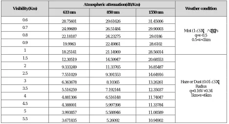
Table 2. A table of atmospheric attenuation in (dB/km) as a function of visibility for difference laser wavelength
Visibility(Km)
Atmospheric attenuation(dB/Km)
Weather condition
633 nm 850 nm 1550 nm
0.6 28.75601 29.61626 31.45006
Mist (1-2) μm Radius q=v-0.5 0.5<v<1km
0.7 24.99689 26.51484 29.90003
0.8 22.18187 24.23275 29.0186
0.9 19.9963 22.49861 28.6102
1 18.25141 21.14969 28.56014
1.5 12.30519 14.59947 20.68553
Haze or Dust (0.01-2) μm Radius q=0.16V+0.34
1km<v<6km
2 9.333249 11.33765 16.85487
2.5 7.551029 9.391553 14.64916
3 6.363678 8.10365 13.26261
3.5 5.516259 7.192144 12.35037
4 4.881306 6.516148 11.74047
4.5 4.388001 5.997398 11.33784
5 3.993857 5.588946 11.08589
5.5 3.671835 5.26092 10.94902
Optical Transmitter
ISSN(Online): 2319-8753
ISSN (Print): 2347-6710
I
nternational
J
ournal of
I
nnovative
R
esearch in
S
cience,
E
ngineering and
T
echnology
(An ISO 3297: 2007 Certified Organization)
Vol. 4, Issue 6, June 2015
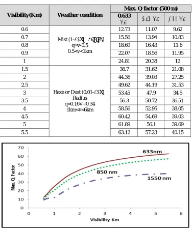
Table 2. A table of visibility Vs, Max. Q. factor for difference laser wavelength
Visibility(Km) Weather condition
Max. Q factor (500 m) 0.633
μm 0.85 μm 1.55 μm
0.6
Mist (1-2) μm Radius
q=v-0.5 0.5<v<1km
12.73 11.07 9.62
0.7 15.56 13.94 10.83
0.8 18.69 16.43 11.6
0.9 22.07 18.56 11.95
1 24.81 20.38 12
1.5
Haze or Dust (0.01-2) μm
Radius q=0.16V+0.34
1km<v<6km
36.7 31.62 21.08
2 44.36 39.03 27.25
2.5 49.62 44.19 31.53
3 53.45 47.9 34.5
3.5 56.3 50.72 36.51
4 58.56 52.95 38.05
4.5 60.42 54.69 39.03
5 61.89 56.1 39.69
5.5 63.12 57.23 40.15
ISSN(Online): 2319-8753
ISSN (Print): 2347-6710
I
nternational
J
ournal of
I
nnovative
R
esearch in
S
cience,
E
ngineering and
T
echnology
(An ISO 3297: 2007 Certified Organization)
Vol. 4, Issue 6, June 2015
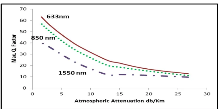
Fig. 5.2 : max. Q factor vs atmospheric attenuation db/Km
VI. RESULTS ANALYSIS
By varying the data rate and the visibility between the two transceivers, the system performance in terms of Q factor was obtained by using different laser wavelengths of 310, 633, 850 and 1550 nm. Then, the system performances were plotted in Fig. 5.1 and 5,2 respectively. The visibility was set from 0.5 km to 6 km while the transmit power was set at a constant value of 8 mW in mist and haze or dust weather. The data rates were set at 3 levels which are fast Ethernet (100 Mbps), asynchronous transfer mode (ATM) (155 Mbps) and Gigabit Ethernet (1.25 Gbps).
Using the mathematical model proposed in Eq. 4 and 6 earlier, the attenuations per kilometer depending on the exponent in the expression for atmospheric attenuation. From the line chart of both Fig. 5.1 and 5.2, it can be observed that maximum Q system increase when visibility is increasing. In other words, it shows that the error in the received signal decreases when the visibility increases too. Besides that, the line chart also shows that with higher data rate, maximum achievable Q factors are also reduced. The relationship between laser wavelength and weather condition was also investigated. The system performance in terms of Q Factor was obtained in three different weathers.
The first scenario is in a clear weather with most of the time, visibility is greater than 10 km. Meanwhile, the second is in lower visibility that to be at 2 km later in the evening. It is believed that in that particular evening, the visibilities lower than normal was due to haze or dust caused by smoke of generators and cars engines.
From the graph of Fig. 5.1 to 5.2, it can be observed that the error in the received signal decreases as the visibility increases due to the value of Q factor that increasing. At the distance of 0.5 km in foggy weather (visibility > 700 m), only wavelength at 1550 nm can be used as the Q factor received does not equal to zero. It also can be declare that laser communication outages due to the attenuation of laser light can be a problem during lower visibility.
VII.CONCLUSION
ISSN(Online): 2319-8753
ISSN (Print): 2347-6710
I
nternational
J
ournal of
I
nnovative
R
esearch in
S
cience,
E
ngineering and
T
echnology
(An ISO 3297: 2007 Certified Organization)
Vol. 4, Issue 6, June 2015
special for laser beam; therefore the effects of scattering dominate the total attenuation coefficient.In fog condition where the visibility is less than (0.5 Km) the atmospheric attenuation take the same value for different laser wavelength, therefore the atmospheric attenuation is independent to the wavelength.By using this theoretical model the atmospheric attenuation caused by scattering can calculated for different laser wavelength and different visibility also we can calculates the atmospheric transmission for different given rang.
REFERENCES
[1] A.C. Boucouvalas, .Challenges in Optical Wireless Communications., in Optics & Photonics News, Vol. 16, No. 5, 36-39 (2005).
[2] I.I. Smolyaninov, L. Wasiczko, K. Cho, C.C. Davis, .Long Distance 1.2 Gb/s Optical Wireless Communication Link at 1550 nm., in Free-Space Laser.
[3] C.C. Davis, I.I. Smolyaninov, .Effect of atmospheric turbulence on bit-error rate in an on-off-keyed optical wireless system,. in Free-Space Laser.
[4] K.B Ayyappa Raddy, Free Space Optic, Madanapalle Institute of Technology and Science, India, (2011).
[5] T. Deng Y. Lu Xiaoxiao, . Performance Evaluation of Free Space Optical Communication System, IEEE, 0-7803-9335-X (2005). [6] R.K. Crane, .Electromagnetic Wave Propagation through Rain., (Wiley, New York, 1996).
[7] Heba Yuksel,.Studies of the Effects of Atmospheric Turbulence on Free Space Optical Communications., (Ph.D. Dissertation, Univ. of Maryland, College Park, 2005).