_____________________________________________________________________________________________________
www.sciencedomain.org
Dynamic Anatomy of Aortic Root and Its Potential
Role in TAVR Prostheses Further Development and
Modification
A. G. Zarayelyan
1*1
Department of Interventional Cardiology, Yerevan State Medical University, Yerevan, Armenia.
Author’s contribution
The sole author designed, analyzed and interpreted and prepared the manuscript.
Article Information
DOI:10.9734/BJMMR/2015/14154 Editor(s): (1)Gaetano Santulli, College of Physicians & Surgeons Columbia University Medical Center New York, NY, USA.
Reviewers: (1) Anonymous, University of Bari, Italy. (2)Akram M. Asbeutah, Radiologic Sciences- Faculty of Allied Health Sciences, Kuwait University, Kuwait. Complete Peer review History:http://www.sciencedomain.org/review-history.php?iid=719&id=12&aid=6970
Received 21st September 2014 Accepted 31st October 2014 Published 15th November 2014
ABSTRACT
Aortic stenosis (AS) is the most common valvular disorder. Surgical aortic valve replacement is the definitive therapy for patients with severe AS. In the last years transcatheter aortic valve replacement (TAVR) has been developed as an alternative to surgical aortic valve replacement with promising results. Despite being less invasive than open-chest aortic valve replacement, good outcome and effectiveness of TAVR procedure, it remains associated with the potential for serious complications and short-time durability. Today there are two TAVR prostheses that have CE marks and FDA approved: Edwards Valves and CoreValve. Besides there are many other newly developed TAVR prostheses on the stage of clinical trials. However, no one of them had been developed on the base of data for dynamic anatomy of human aortic root because of the lack of appropriate imaging modality. Today, different two-dimensional (2D) and three-dimensional (3D) imaging techniques are used for aortic root examination. But no one of them has been accepted as a “gold standard” imaging modality for assessment of dynamic anatomy of aortic root. The existing imaging modalities such as transthoracic echocardiography, transesophageal echocardiography, angiography, CT and MRI scans provide tangential cut plane view which did not reflect the real sizes of the annulus and other aortic root rings and structures. Obtained with these modalities images did not reflect the changes of the size and shapes of the anatomic structures of aortic root during the different phase of cardiac cycles either. Today there are strict needs for imaging
Zarayelyan; BJMMR, 5(12): 1534-1546, 2015; Article no.BJMMR.2015.173
modality which could assist in assessment of dynamic aortic root to push the TAVR prosthesis design and modification on new level.
Keywords: Dynamic anatomy of aortic valve; imaging modality; TAVR prosthesis.
1. INTRODUCTION
Although the cardiovascular disorder represents the foremost cause of preventable death, according to the World Health Organization (WHO) it still the first cause of death globally and accounts for approximately 30% of all deaths [1].
Aortic stenosis (AS) is the commonest valvular disease in adults that affects 2% to 5% of the population, and its prevalence is going to increase dramatically with the aging of the population in all over the world [2,3,4]. At present, surgical aortic valve replacement (SAVR) is considered the gold standard for treatment of patients with symptomatic, severe aortic stenosis who are at low or intermediate surgical risk as estimated by the logistic EuroSCORE or Society of Thoracic Surgeons’ (STS) score. In patients who are deemed high risk or inoperable for conventional SAVR, transcatheter aortic valve replacement (TAVR) alternatives have been developed since 2002 and become a rapidly evolving technique using either balloon-expandable [5] or self-expanding valve [6,7] deployment systems. Using standard open-heart surgical techniques, the old valve is excised and a new valve is sutured into place. With the catheter based approach, the TAVR, the old valve is left in situ and a new valve mounted within a stent is inserted into the old valve. The stent then either expands itself, a so-called self-expanding device or the stent is expanded with a balloon to open up and relieve the obstruction caused by the diseased valve. Two devices are currently available and marketed in Europe and around the world: the Edwards Sapien balloon
expandable bioprosthesis (Edwards
Lifesciences, Irvine, CA, USA) and the
Medtronic-CoreValve self-expanding
bioprosthesis (Medtronic Inc, Minneapolis, MN, USA). There are many other newly developed TAVR prostheses on the stage of clinical trials.
According to multiple published data the success rate of TAVR for both devices was ranged from 89 to 98%. The pressure gradient was improved significantly from 41.6±16.4 mmHg to final mean gradient of 8.1±3.8 mmHg and the mean effective orifice area increased from
0.75±0.23cm2 to 1.97±0.85 cm2 [8]. Overall functional status assessed by NYHA class improved from 3.3±0.5 to 1.7±0.7 and remaining stabile in the follow-up [6]. Despite being less invasive than open-chest aortic valve
replacement and good outcome and
effectiveness of TAVR procedure, it remains associated with the potential for serious complications and still confined to the treatment of elderly and high-risk patients [9].
Risks associated with TAVR differ from those related to surgical valve replacement and include vascular injury; stroke; cardiac injury such as heart block, coronary obstruction, and cardiac perforation; paravalvular leak (PVL); and valve misplacement. The most frequent modes of failure are moderate to severe aortic regurgitation (mostly as a paravalvular leak) (from 67% to 77% [10]), aortic valve area (AVA) <1.2 cm2 (from 3.0% to 6.6%), AV conduction disturbances (from 4% to 30%) and failure of delivery or implantation of the valve in the correct position (from 2.2% to 5.6%) [11].
Today there is evidence for the link between annulus size measured by methods currently available and PVL and AV conduction disturbance (AVCD). The occurrence of significant PVL is related to under sizing of aortic annulus, resulting in incongruence between the annulus and the device. Conversely, the systematic implantation of oversized prostheses or balloon re-expansion already implanted prosthesis might decrease the frequency of PVL occurrence, but lead to AV conduction disturbance or even to aortic annulus rupture [9,12].
Current understanding of the potential adverse events associated with TAVR procedure is
limited. Awareness of how complications occur might help in their avoidance, recognition,
Accurate aortic annulus size evaluation is difficult and might require different technique. The knowledge of the limitations of measuring the aortic annulus and aortic root structures by echocardiography, angiography, or computed tomography and development of new more accurate imaging modalities may decrease the possibility of patient-prosthesis mismatch.
Besides, the presence of conformational changes in the aortic root during the cardiac cycle is well known, but precise information on time-related changes at each level of the aortic root in alive human is lacking. However, dynamic anatomy of aortic root may play important role in TAVR procedure complications and further changes of the shape and functionality of implanted valve during short and long-term follow-up (Fig. 1.1 and Fig. 1.2.) [4,14].
2. DYNAMIC ANATOMY OF AORTIC ROOT
It is paramount important to be familiar with the anatomic relationship between aortic root structures and its changes during cardiac cycle for development and design of effective transcatheter implanting aortic valve with decreasing the complication rate and increasing its durability. The profound knowledge of the underlying to aortic root cardiac anatomy is mandatory to understand function, both normal and abnormal.
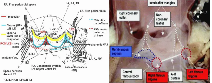
The aortic root is defined as the junction site between the left ventricle and the ascending aorta and consists of a short tube. The lower part of this tube connects for approximately two thirds of its circumference to the interventricular septum, whereas the remaining part (1/3) connects to the fibrous tissue of the aortic (or anterior) leaflet of the mitral valve. The non-coronary leaflet is exclusively fibrous. The right coronary leaflet attaches to the predominantly muscular region of the LV outflow tract (LVOT). Whereas left coronary leaflets can contain small portions of ventricular muscle. This could play a role in changes of shape of aortic root during cardiac cycle. The upper part of the tube fuses with the ascending aorta. The aortic valve leaflets are attached in a semilunar fashion, thus producing valve leaflets called the sinus of Valsalva. The coronary arteries originate from the sinuses of Valsalva and the ostia are usually positioned below the level of the sinus ridge. The right and left coronary sinuses consist mainly from muscular and elastic fibers, while
non-coronary sinus – from fibrous. This consistence and anatomy might be changed significantly in case of abnormalities in coronary vessels origins [15]. This is play role in dynamic anatomy changes during cardiac cycle and should be considered in prosthesis design. At the same time, the curved attachments of the valve leaflets create triangular spaces between the two lines of attachment of adjacent leaflets, known as the interleaflet triangles (Fig 2 A. B.) [14,16,17]. These triangles are part of the aortic root, but haemodinamicaly are more related to the left ventricular cavity rather than to the aorta (Fig 2 B.) [14]. Apices of the triangles form the highest point of the attachment of leaflets. These points, referred to as the commissures, insert into the sinus ridge, which marks the site of the sinotubular junction. Thus represents the junction between the aortic root and the ascending aorta. The base of the interleaflet triangles is represented by LVOT with the most extensive muscular component (between right and left coronary leaflets and between right and non-coronary leaflets) and a less extensive fibrous component (between non-coronary and left coronary leaflets) (Fig 2.A) [16]. This arrangement immediately reveals that aortic valve function cannot be considered without taking into account the consistence of interleaflets triangles, functional status of the mitral valve apparatus and the left ventricular myocardium. In fact, the part of the aortic valve attached directly to the mitral valve is exposed to different tensile forces compared with the part attached to the myocardium. During left ventricular ejection, the “fibrous part” will be fully exposed to the systolic forces, very much like the mitral valve. The line of attachment between the aortic and mitral valves spans approximately one third of the total aortic valve circumference. These arrangements of dynamic anatomy of aortic root with appropriate its functioning did not accounted in designing not for surgical prostheses neither for TAVR prostheses.
The features as the position of the aortic ostium in relation to the outflow part of the ventricular septum, the subaortic angulation, and the angulation between the aortic and mitral valve planes are affected by age and has not only surgical significance but also important for TAVR.
Fig. 1.1. Different shapes of TAVR (A)
Fig. 1.2. Influence of size or shape of the
No leaflet distortion is present (A). Distortion occurred after TAVR deployment in an elliptic (B), a
or an undersized circular orifice (D). (Zegdi et al. Valved Stent in Aortic Stenoses. JACC Vol. 51, No. 5,
Fig. 2. A.B. Anatomic structures of aortic root which play
A. R/L ILT – interleaflet triangle between right and left coronary leaflets; N/R ILT non-coronary and right coronary leaflets; L/N ILT
leaflets; RCS – right coronary sinus; L
ventriculoarterial junction. (Sutton J.P. et al. The Forgotten Interleaflet Triangles: A Review of the Surgical Anatomy of the Aortic Valve. Ann Thorac Surg 1995).
B. The image of the aortic root opened from the left ventricle shows the fibrous continuities between the interleaflet triangles, the fibrous trigones, and the membranous septum. A
Anatomy of the Aortic Valvar Complex and Its Implications for Transc
Circulation: Cardiovascular Interventions. 2008).
the aortic sinuses are in close contact with both the right and left atrium and the right ventricular outflow tract (RVOT). The right coro
Zarayelyan; BJMMR, 5(12): 1534-1546, 2015; Article no.
Fig. 1.1. Different shapes of TAVR prosthesis after deployment (A) Circular; (B) Triangular; (C, D) Elliptic
Fig. 1.2. Influence of size or shape of the aortic orifice on the TAVR prosthesis No leaflet distortion is present (A). Distortion occurred after TAVR deployment in an elliptic (B), a
or an undersized circular orifice (D). (Zegdi et al. Valved Stent in Aortic Stenoses. JACC Vol. 51, No. 5, 2008:579-84)
Fig. 2. A.B. Anatomic structures of aortic root which plays role in function of aortic valve interleaflet triangle between right and left coronary leaflets; N/R ILT - interleaflet triangle between coronary and right coronary leaflets; L/N ILT - interleaflet triangle between left coronary and non
right coronary sinus; LCS – left coronary sinus; NCS – non-coronary sinus; VAJ Sutton J.P. et al. The Forgotten Interleaflet Triangles: A Review of the Surgical Anatomy of the Aortic Valve. Ann Thorac Surg 1995).
ened from the left ventricle shows the fibrous continuities between the interleaflet triangles, the fibrous trigones, and the membranous septum. A-M- aortic-mitral. (Piazza N, et al.
Anatomy of the Aortic Valvar Complex and Its Implications for Transcatheter Implantation of the Aortic Valve. Circulation: Cardiovascular Interventions. 2008).
the aortic sinuses are in close contact with both the right and left atrium and the right ventricular outflow tract (RVOT). The right coronary leaflet
largely relates to the RVOT, but the site adjacent to the commissural junction with the non coronary leaflet may relate to the right atrium.
; Article no.BJMMR.2015.173
prosthesis
No leaflet distortion is present (A). Distortion occurred after TAVR deployment in an elliptic (B), a triangular (C), or an undersized circular orifice (D). (Zegdi et al. Valved Stent in Aortic Stenoses. JACC Vol. 51, No. 5,
role in function of aortic valve interleaflet triangle between interleaflet triangle between left coronary and non-coronary
coronary sinus; VAJ – Sutton J.P. et al. The Forgotten Interleaflet Triangles: A Review of the Surgical
ened from the left ventricle shows the fibrous continuities between the Piazza N, et al. [7] atheter Implantation of the Aortic Valve.
The non-coronary leaflet relates to both the right and left atrium. The left coronary leaflet, in part, relates to the left atrium and faces the pericardial sac between the pulmonary trunk and the left atrial appendage. Moreover, both the non-coronary and the left non-coronary leaflets relate intimately to the aortic leaflet of the mitral valve. The knowledge of this intracardiac structure relationship is very important to understand the mechanisms of potential complication after TAVR and may assist in modifications of prostheses placement and design.
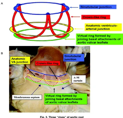
Therefore, in the strict sense, there is no aortic valve ring (or annulus). Indeed, several “rings” can he identified (Fig. 3) [18]. First, the sinotubular junction demarcated by the sinus ridge and the related commissural sites of the aortic valve leaflets. This plane actually represents the outlet of the aortic root. Second is the annular junction at the lower border of the aortic root, produced by the lower point of attachments of the valve leaflets. Basically, this plane represents the inlet from the LVOT into the aortic root. In general, the inlet diameter exceeds that of the outlet by 15% to 20%. Reid K et al, using fixed human hearts, calculated an inlet/outlet radius of 1.34 [19]; Kunzelmann et al. using cryopreserved normal aortic root specimens, measured an inlet diameter of 23.4 (±1.2) mm and an outlet diameter of 18.9 (±2.09) mm. The third annulus is a line through the middle part of the expanded sinuses. Measurements at this level produce the largest diameter of the aortic root, which, in adults, approximates 3 cm. Reid et al., described the aortic root as a truncated cone. In other words, it is important to know what level of the aortic root has been measured once a diameter is produced.
The normal aortic valve is a tri-leaflet structure in which the valve leaflets, together with the sinuses, the commissural sites, and the sinus ridge form a functional unit. For instance, proper leaflet coaptation depends on proper relationships between these structures. However, not only does interindividual variation occur, but in the same individual marked differences exist in leaflet dimensions, both with respect to leaflet width as well as leaflet height. This anatomic specification gets more variations in the presence of abnormalities in coronary vessels origins [15]. This is very important to take in
consideration all this specifications and they role when designing the prostheses for TAVR. Many investigators had shown in animal experiment that the diameters of the aortic root at its different level have the different sizes and changes in different way during cardiac cycle. There is no any accepted explanation for these differences in diameters changes at the different level of aortic root during cardiac cycle. The diameter of the aortic root at the level of basal ring (BR) compared with the diameter at the middle of the Sinus Valsalva level decreased slightly (97%) and decreased significantly at the level of sinotubular junction (STJ) (81%). There is no data regarding the changes of these diameters during cardiac cycle.
The measuring of the movement of the wall of aortic root at the coaptation level of leaflet in animal had revealed a 16% diameter change during each cardiac cycle. The dimensional changes observed can by themselves explain aortic valve function and obviate the postulation that the leaflets shorten and lengthen during each cardiac cycle. Such a dynamic aortic root may explain the longevity of the actual aortic leaflets, in that leaflet fatigue stress is minimized by changes in aortic root dimension. However, this specificity of dynamic anatomy of aortic root completely discarded in aortic prosthesis design especially in TAVR.
According to multiple literature data [14,20,21] the difference between sagittal and coronal diameters of aortic annulus in human is vary of 15-22%, which is clearly demonstrating the ellipsoid (oval) shape of aortic annulus. Thus, as had been described by Messika-Zeitoun D. [20], the coronal diameter of the aortic annulus at the level of the virtual basal ring was 27,5±3,1 mm and the sagittal diameter 21,7±2,3mm. The mean of sagittal and coronal diameters (24.6±2.4 mm) tended to be significantly larger than TTE and TEE measurements. The diameter of the aortic annulus was determined by authors in diastole. There is no any information regarding the changes of this diameter during systole.
Zarayelyan; BJMMR, 5(12): 1534-1546, 2015; Article no.BJMMR.2015.173
Fig. 3. Three “rings” of aortic root
A. Three-dimensional arrangement of the aortic root, which contains 3 circular “rings.” B. The leaflets have been removed from this specimen of the aortic root, showing the location of the 3 rings relative to the crown-like hinges
of the leaflets. VA – ventriculo-arterial; A-M - aortic-mitral.
(Piazza N, et al. [7] Anatomy of the Aortic Valvar Complex and Its Implications for Transcatheter Implantation of the Aortic Valve. Circulation: Cardiovascular Interventions. 2008)
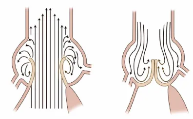
The model demonstrates the formation of fluid flow eddies and explains the effects on opening and closing of the leaflets. According to Bellhouse's model, early in systole the leaflets move toward the sinuses and vortices form between the leaflet and sinus wall [23]. Flow enters at the ridge of the STJ, curls along the wall, and then flows back into the main stream. On valve opening, these eddies prevent the aortic leaflets from impacting on the aortic wall. Eddies also promote valve closure. After peak systole, eddies force the leaflets to move away
A. Leonardo da Vinci 1508 B. Belhouse Cir Res 1969 C. Kilner Circulation 1993 (3D MRI)
Fig. 4. Importance of sinuses of valsalva
Recirculating flows (vortices) accommodated by the sinuses contribute to efficient and smooth valve closure at end systole. (Lansac E., Di Centa I. EJTCS 2002; 22:497-503)
Fig. 5. Mechanism of leaflets closure: the role of the sinuses
(Rugero de Paulis. Aortic Valve and Aortic root Anatomy. 22nd Annual Conference of the Saudy Heart
Association. 2011)
Though the exact shape of the sinus may not have a direct effect on initial eddy formation, it does affect valve function in other ways. The importance of sinus curvature and its effect on stress distribution with the leaflets has been studied with the use of marker fluoroscopy techniques in dogs. It has been observed that the diastolic shape of the sinuses is nearly spherical and the shape of the leaflets is cylindrical (in the load-bearing area). By engineering analysis, the stress carried by the leaflets in diastole was calculated to be four times as high as the stress in the sinuses. If the leaflet stress was not shared with the sinuses, the sinus walls would be pulled inward during diastole. The marker studies
demonstrated that the sinus walls move outward instead, implying that part of the load on the leaflets is taken up by the sinus walls. This stress sharing decreases the stress and the wear on the leaflets.
Theoretically, after transcatheter implantation of aortic valve without sinus component or with metallic components inside of the sinuses the sinus walls is not sharing the stress of the prostheses leaflets, which may be one of the main reasons of low functioning, less durability and early deformation, damage or calcification of implanted valve leaflets (Fig. 1) [14].
Zarayelyan; BJMMR, 5(12): 1534-1546, 2015; Article no.BJMMR.2015.173
root replacement may not be geometrically suited to take up stress from the leaflets. Abnormal stress on the leaflets may decrease the potential longevity of the repair. An optimal design for root replacement would incorporate sinuses and a sinus ridge to promote proper valve opening and closure, as well as decreased stress on the leaflets.
Lansac E. and coauthors [24] had applied the high-resolution, 3D sonomicrometry (200 Hz) in an acute sheep model. Twelve ultrasonic crystals were implanted in eight sheep at each base (n = 3), commissure (n = 3), sinotubular junction (n = 3) and ascending aorta (n = 3). This imaging modality had allowed authors reveal that the aortic root geometric changes were time-related to each phase of the cardiac cycle. The present study considered that the normal aortic root is basically formed by three unequal sinuses of Valsalva that, by behaving differently during the cardiac cycle, determine significant conformational changes of the whole root that might have hemodynamic consequences.
Thus, the presence of conformational changes in the aortic root during the cardiac cycle is well known from experimental animal models. But there is no precise information on time-related changes at each level of the root in humans because of absence of appropriate for this purpose imaging modality. There is obvious necessity to investigate dynamic changes of aortic root structures during cardiac cycle phases in human to reveal its specificities for developing highly effective aortic valves. However, available today 2D and 3D imaging modalities provide indirect tangential cut-plane visualization of aortic root without consideration of cardiac cycle phase.
3. ANALYSES OF ADVANTAGES AND LIMITATIONS OF EXISTING TODAY IMAGING MODALITIES IN REGARDS TO ASSESSMENT OF AORTIC ROOT
Today, different two-dimensional (2D) and three-dimensional (3D) imaging techniques are used for aortic root assessment, TAVR procedure planning and selection of prosthesis size before transcatheter aortic valve implantation [25].
The measurement of the aortic annulus obtained by the most frequently used imaging modalities 2D transthoracic and 2D transesophageal echocardiography (2D TTE, 2D TEE) and contrast angiography are limited by their two-dimensional (2D) nature and allowing analyses of
the annulus diameter in just one view, which lead to underestimation of the maximal valve annulus diameter. To adjust for this, CT has recently been suggested for improved preprocedural measurement of aortic annulus and prosthesis sizing. 3D transesophageal echocardiography (3D TEE) allows analysis of cardiac structures in any view similar to CT.
As have been recently clinically confirmed by many investigators with the use of three-dimensional (3D) imaging technique (3D TEE, CT, MRI), the aortic annulus has an ellipsoid geometry with medium to significant difference between diameters obtained in sagittal and coronal views (5-20%) [20,21,25,26]. Ellipsoid shape of the aortic annulus results in a larger diameter in the coronal direction and a smaller diameter in sagittal direction.
Two-dimensional echocardiography (2D TTE and 2D TEE) has been the most commonly and widely used imaging modality for aortic annulus measurement and prosthesis size selection and thus it considered as the reference method. It plays a key role in a patient’s evaluation before TAVR and during the procedure [8]. It is widely available, repeatable, and easy to perform even if TEE is semi-invasive and usually requires sedation or general anesthesia. But, it should be
noted, that measurements taken by
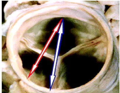
echocardiographers from the basal attachment of one leaflet to the comparable point of an adjacent leaflet in the parasternal long-axis view do not transect the full diameter of the outflow tract but instead cut a tangent across the root, which lead to underestimating of aortic annulus diameter (Fig. 6) [18]. In terms of percutaneous replacement, irrespective of the type of valve inserted, it is this echocardiographic measurement that has played a crucial role in the selection of the size of prosthesis to be inserted and leaded to patient-prosthesis mismatch [14].
during the remainder of systole and isovolumetric relaxation. Annulus again moved in the cranial direction during diastole. Due to variability of the position of the heart within the chest, the acoustic windows of 2D TTE and 2D TEE provide variable views of the aortic annulus, which deviate also from the sagittal view obtained by CT [25,26].
Fig. 6. The basal short-axis view shows the closed aortic valve
The arrows demonstrate the potential hazard of echocardiography for measuring the “aortic valve
annulus.” Measurements made using the basal attachment of the leaflets do not transect the full diameter of the outflow tract but instead a tangent cut
across the root. (Piazza N, et al. [7] Anatomy of the Aortic Valvar Complex and Its Implications for Transcatheter Implantation of the Aortic Valve. Circulation: Cardiovascular Interventions. 2008)
Contrast angiography in 90° left anterior oblique (LAO) projection allows the measurement of the sagittal diameter of aortic annulus and 0° posterio-anterior (PA) projection - the coronal annulus diameter (Fig. 7. A.). However, the 0° PA and 90° LAO projections do not always provide perpendicular to the aortic annulus views, as has been shown by Kurra et al. [25,28]. This may lead to imprecise measurements of the
aortic annulus diameters. However,
individualized definition of angiographic views perpendicular to the aortic annulus may require acquisition of multiple views and is therefore not used in clinical practice.
Thus, angiography too is likely to be the least accurate technique for defining aortic annulus diameters, as it is a 2D imaging technique with projections that may not adequately reflect the largest diameter and potentially largest calibration difficulties before measurement of annulus size. Furthermore, aortic bulbus
distortion, severe aortic calcification and insufficient contrast enhancement may impair accurate measurements of the aortic annulus diameter using angiography. Rotational angiography, which has recently become available, may enable improvements in the angiographic assessment of aortic annulus diameters [25].
TEE and fluoroscopy have different strengths [29]. Ultrasound imaging becomes more helpful in patients with less intracardiac calcium, where fluoroscopy is less effective. Conversely, fluoroscopy becomes more helpful in patients who have more calcification, because cardiac motion becomes more apparent, whereas TEE becomes more difficult because of shadowing [29]. However, dependence on fluoroscopic visualization of the native valve is problematic owing to variability in the amount and location of calcification [30].
In contrast to 2D imaging modalities, newer modalities such as multislice computed tomography (Fig 7. C.) [25], 3-dimensional echocardiography, and magnetic resonance (Fig 7. D.) imaging are emerging as attractive modalities for imaging because they permit precise measurement of the aortic root at any desired level or plane, and thus they may provide more accurate measurements of the true dimensions of the different components of the aortic valve complex.
Zarayelyan; BJMMR, 5(12): 1534-1546, 2015; Article no.BJMMR.2015.173
Fig. 7. Models of the aortic arch showing for each applied imaging modality the cut planes of the aortic annulus
(Altiok E. et al. Comparison of two-dimensional and three-dimensional imaging techniques for measurement of aortic annulus diameters before transcatheter aortic valve implantation. Heart. 2011)
Use of Computed Tomography (CT) has been recommended recently for improved sizing of the prosthesis to prevent patient-prosthesis mismatch [10]. CT allows a three-dimensional (3D) acquisition of the entire heart throughout the cardiac cycle and multiple plane reconstructions with a high spatial resolution (Fig 7. C.). Three-chamber view has the same orientation as the parasternal long-axis view on TTE and the 120° long-axis view on TEE. During CT the standard orthogonal axial and sagittal views are used for orientation on the aortic valve. As the aortic valve is oriented obliquely to the standard axial view, a
coronal and a single oblique sagittal view through the aortic valve are usually reconstructed using CT datasets. The in-plane resolution of computed tomography is less than 1 mm and the minimum through-plane resolution is approximately 1.25 to 1.50 mm. Iodine injection and radiation exposure are important MSCT limitations.
The specifications, advantages and limitations each available today of imaging modalities for aortic root examination are summarized in Table N1.
Table N1. The specifications, advantages and limitations of available today imaging modalities for aortic root examination
adv & limitation
Specifications Imaging modality
2D TTE 2D TEE angio 3D TEE CT / MRI
adv dimension 3D 3D 3D
lim 2D 2D 2D
adv measurement
diameters
sagittal & coronal
sagittal & coronal
sagittal & coronal
lim sagittal sagittal
adv cut plane 0° PA -
coronal 90° LAO - sagittal
at any plane or level (orthogonal or oblique planes)
at any plane or level (orthogonal or oblique planes)
lim tangential
across the aortic root
tangential across the aortic root
not
perpendicular to aortic annulus
not
perpendicular to aortic annulus;
additive effect of accumulative errors
Standard orthogonal axial & sagittal views need to be reconstructed for obliquely oriented aortic valve.
adv resolution in-plane <1,0mm
lim 3-5mm 3-5mm 3-5mm 3-5mm through plane
1,25-1,5mm
4. CONCLUSION
Thus, dynamic aortic root has different sizes on its different levels. During cardiac cycle phases the structures of aortic root are changing their shape and size in the way that determine the stress share with consequent long lasting longevity of the aortic valve. In this stress share and long lasting longevity processes the different mechanisms of aortic root dynamic are involved. There is no any investigation of dynamic anatomy of aortic root during cardiac cycle phases in human because of absence of appropriate for this purpose imaging modality with direct visualization of aortic valve and root. However, the understanding of dynamic anatomy of aortic root in different phase of cardiac cycle undoubtedly may have very important impact not only in aortic valve disease development process discovery, but also in proper development and design of new or existing aortic valve prostheses in accordance with its physiology and dynamic anatomy for TAVR with minimal rate of complication and long lasting longevity.
Today for farther development of TAVR technology it is necessary:
- to turn the look to investigation of dynamic anatomy of aortic root during cardiac cycle in human;
- to find out among existing or develop a new imaging modality for direct visualization of aortic root during cardiac cycle in human;
- to reveal important pattern of dynamic anatomy of aortic root which are responsible for functioning, stress sharing and longevity of aortic valve in alive human;
- to apply obtained specifications in further AOV development and design;
Until now, however, little consideration has been given to understanding the dynamic anatomy of
aortic root with percutaneous replacement of the valve in mind.
CONSENT
Not applicable.
ETHICAL APPROVAL
Not applicable.
COMPETING INTERESTS
Author has declared that no competing interests exist.
REFERENCES
1. Santulli G. Epidemiology of cardiovascular disease in the 21st century: updated numbers and updated facts. Journal of cardiovascular disease. 2013;1(1). ISSN: 2326-3121.
2. Aronow WS, Kronzon I. Prevalence and severity of valvular aortic stenosis determined by Doppler echocardiography and its association with echocardiographic and electrocardiographic left ventricular hypertrophy and physical signs of aortic stenosis in elderly patients. Am J Cardiol. 1991;67:776-777.
3. Kovac J, Baron JH, Chin DT. Are the standard criteria for TAVI too lax or too strict? Heart. 2010;96:5–6.
4. Zegdi R, Ciobotaru V, Noghin M, Sleilaty G, Lafont A. Latrémouille Christian, is it reasonable to treat all calcified stenotic aortic valves with a valved stent? JACC 2008;51(5):579–84.
Zarayelyan; BJMMR, 5(12): 1534-1546, 2015; Article no.BJMMR.2015.173
6. Grube E, Buellesfeld L, Mueller R, Sauren B, Zickmann B, Nair D, et al. Progress and current status of percutaneous aortic valve replacement: results of three device generations of the CoreValve revalving system. Circ. Cardiovasc Interv. 2008;1:167-175.
7. Piazza N, Grube E, Gerckens U, den Heijer P, Linke A, Luha O, et al. Procedural
and 30-day outcomes following
transcatheter aortic valve implantation using the third generation (18 Fr) CoreValve revalving system: results from the multicentre, expanded evaluation registry 1-year following CE Mark approval. EuroIntervention. 2008;4:242-249.
8. Moss RR, Ivens E, Pasupati S, Humphries K, Thompson CR, Munt B, et al. Role of echocardiography in percutaneous aortic valve implantation. JACC. 2008;1:15–24. 9. Ussia GP, Barbanti M, Petronio AS,
Tarantini G, Ettori F, Colombo A, et al. Transcatheter aortic valve implantation: 3-year outcomes of self-expanding CoreValve prosthesis. Eur Heart J. 2012;33(8):969-976.
10. Delgado V, Ng ACT, van de Veire NR, van der Kley F, Schuijf JD, Tops LF, et al. Transcatheter aortic valve implantation: Role of multi-detector row computed tomography to evaluate prosthesis positioning and deployment in relation to valve function. Eur Heart J. 2010;31:1114-23.
11. Généreux P, Head SJ, Van Mieghem NM, Kodali S, Kirtane AJ, Xu K, et al. Clinical outcomes after transcatheter aortic valve replacement using valve academic research consortium definitions a weighted meta-analysis of 3,519 Patients From 16 Studies. JACC. 2012;59(25):2317–26. 12. Détaint D, Lepage L, Himbert D, Brochet
E, Messika-Zeitoun D, Iung B, et al. Determinants of significant paravalvular regurgitation after transcatheter aortic valve implantation. JACC: Cardiovascular Interventions.2009;2(9):821-7.
13. Masson JB, Kovac J, Schuler G, Ye J, Cheung A, Kapadia S, et al. Transcatheter aortic valve implantation. J Am Coll Cardiol Intv. 2009;2:811–20.
14. Piazza N, de Jaegere P, Schultz C, Becker AE, Serruys PW, Anderson RH. Anatomy of the aortic valvar complex and its implications for transcatheter implantation of the aortic valve. Circulation: Cardiovascular Interventions. 2008;1:74-81
15. Fiorella A, Basso P, Lanzone S, Capestro F, Basile DP, et al. Anomalous origin of the coronary arteries: Five case reports and review of the literature. G Ital Cardiol (Rome). 2010;11(10):778-82.
16. Sutton JP, Ho SY, Anderson RH. The forgotten interleaflet triangles: A review of the surgical anatomy of the aortic valve. Ann Thorac Surg. 1995;59:419-27. 17. Thubricar M, Piepgrass WC, Shaner TW,
Nolan SP. The design of normal aortic valve. Am J Physiol Heart Circ Physiol. 1981;241:795-801.
18. Ruggero De Paulis. Aortic valve and aortic root anatomy. 22 Annual Conference of the Saudy Heart association; 2011.
19. Reid K. The anatomy of the sinus of valsalva. Thorax. 1970;25:79-85.
20. Messika-Zeitoun D, Serfaty JM, Brochet E, Lepage L, Detaint D, Hyafil F, et al. Multimodal assessment of the aortic annulus diameter: Implications for Transcatheter Aortic Valve Implantation. J. Am. Coll. Cardiol. 2010;55:186-194. 21. Schultz CJ, Moelker A, Piazza N, Tzikas A,
Otten A, Nuis RJ, et al. Three dimensional evaluation of the aortic annulus using multislice computer tomography: Are manufacturer’s guidelines for sizing for percutaneous aortic valve replacement helpful? Eur Heart J. 2010;31:849-56. 22. Lansac E, Di Centa I. EJTCS.
2002;22:497-503.
23. Bellhouse BJ. The fluid mechanics of the aortic valve. In: Ionescu ML, Ross DN, Woller GH, eds. Biological tissue in heart valve replacement. London: Butterworth-Heinemann. 1972;23-47.
24. Lansac E, Hou-Sen L, Yu S, Hiang LK, Rice NT, Goetz WA, et al. Aortic root dynamics are asymmetric. The Journal of Heart Valve Disease. 2005;14:400-407. 25. Altiok E, Koos R, Schroder J, Brehmer K,
Hamada S, Becker M. et al. Comparison of two-dimensional and three-dimensional imaging techniques for measurement of aortic annulus diameters before transcatheter aortic valve implantation. Heart. 2011;97:1578-1584.
aortic valve area measurements using
two-dimensional transoesophageal
echocardiography and the potential of three-dimensional transoesophageal echocardiography. European Journal of Echocardiography. 2010;11:369–376. 28. Kurra V, Kapadia SR, Tuzcu EM,
Haliburton SS, Svensson L, Roselli EE, et al. Pre-procedural imaging of aortic root orientation and dimensions: Comparison between X-ray angiographic planar imaging and 3-dimensional multidetector
row computed tomography. JACC
Cardiovasc Interv. 2010;3:105e13.
29. Stewart WJ. Imaging the future of transcatheter aortic valve replacement.
JACC: Cardiovascular Imaging.
2008;1(1):25- 8.
30. Webb JG, Chandavimol M, Thompson CR, Ricci DR, Carere RG, Munt BI, et al. Percutaneous aortic valve implantation retrograde from the femoral artery. Circulation. 2006;113:842–50.
31. Chin D. Echocardiography for
transcatheter aortic valve implantation.
European J Echocardiography.
2009;10:i21-9.
32. Ng ACT, Delgado V, van der Kley F, Shanks M, van de Veire NRL, Bertini M, et al. Comparison of aortic root dimensions and geometries before and after transcatheter aortic valve implantation by 2- and 3-dimensional transesophageal echocardiography and multislice computed tomography. Circ Cardiovasc Imaging. 2010;3:94-102.
33. Kühl HP, Schreckenberg M, Rulands D, Kathon M, Schafer W, Schummers G, et al. High-resolution transthoracic real-time three-dimensional echocardiography: quantitation of cardiac volumes and function using semi-automatic border detection and comparison with cardiac magnetic resonance imaging. J Am Coll Cardiol. 2004;43:2083-90.
© 2014 Zarayelyan; This is an Open Access article distributed under the terms of the Creative Commons Attribution License (http://creativecommons.org/licenses/by/4.0), which permits unrestricted use, distribution, and reproduction in any medium, provided the original work is properly cited.
Peer-review history: