Optimization of Shielding- Collimator Parameters for
ING-27 Neutron Generator Using MCNP5
Aya Hamdy Hegazy 1,*, V. R. Skoy 2, and K. Hossny 1
1 Nuclearand Radiation Engineering department, Faculty of Engineering, Alexandria University, Alexandria Egypt.
2 Joint Institute for Nuclear Research (JINR), Joliot Curie St., 6, 141980 Dubna, Russian Federation.
Abstract. Neutron generators are now used in various fields. They produce only fast neutrons; D-D neutron generator produces 2.45 MeV neutrons and D-T produces 14.1 MeV neutrons. In order to optimize shielding-collimator parameters to achieve higher neutron flux at the investigated sample (The signal) with lower neutron and gamma rays flux at the area of the detectors, design iterations are widely used. This work was applied to ROMASHA setup, TANGRA project, FLNP, Joint Institute for Nuclear Research. The studied parameters were; (1) shielding-collimator material, (2) Distance between the shielding-collimator assembly first plate and center of the neutron beam, and (3) thickness of collimator sheets. MCNP5 was used to simulate ROMASHA setup after it was validated on the experimental results of irradiation of Carbon-12 sample for one hour to detect its 4.44 MeV characteristic gamma line. The ratio between the signal and total neutron flux that enters each detector was calculated and plotted, concluding that the optimum shielding-collimator assembly is Tungsten of 5 cm thickness for each plate, and a distance of 2.3 cm. Also, the ratio between the signal and total gamma rays flux was calculated and plotted for each detector, leading to the previous conclusion but the distance was 1 cm.
1. Introduction
Neutron generators are now used in various fields and their applications are enormously increasing. They produce only fast neutrons; the D-D neutron generator produces 2.45 MeV neutrons and the D-T produces 14.1 MeV neutrons. One of the problems of neutron generators is optimization of the parameters of neutron-gamma shielding-collimator assembly [1]. The purpose of the optimization is to reach an acceptable value of the ratio between neutron flux in the investigated sample (the signal) and neutron flux in the area of the detectors (the background) also to reach as low as possible gamma rays from inelastic scattering of fast neutrons with the shield. Various simulations and experiments are needed for the design of the shielding-collimator assembly.
E.S.Konobeevsky et al, have optimized the collimator and shielding of the NG 430 neutron generator at the Institute for Nuclear Research, Russian Academy using the MCNP5 and
SHIELD transport codes [2]. D.L. Chichester et al, have optimized the biological shield for D-T neutron generator. The modeling used in these simulations was performed using the MCNP 4C Monte Carlo code [3]. Bergaoui et al. have optimized a neutron radiography system for non-destructive testing that uses 2.45 MeV D-D neutron generator using Monte Carlo N-Particle Transport Code (MCNPX 2.7.0) [4].
This work was applied on ING 27 D-T neutron generator, TANGRA (TAgged Neutron and Gamma RAys) for studying neutron-induced nuclear reactions, ROMASHA setup, Frank laboratory of neutron physics (FLNP), Joint Institute for Nuclear Research (JINR) [5]. The studied parameters were; (1) the shielding-collimator material; three materials were studied; Iron, Tungsten, and Tungsten alloy (90% Tungsten, 7% Nickel, and 3% Iron), (2) the distance between the shielding-collimator assembly’s first plate and the center of the neutron beam; the distance was varied from 0.1 cm to 5.6 cm with 56 bins, while the other distances were set to be functions of the studied distance, and (3) the thickness of shielding-collimator sheets; two thicknesses for each plate were studied 4 cm and 5 cm. The criterion upon which the different collimator parameters were evaluated was based on the ratio between the flux read by the detector and the flux reaching the sample for both neutrons and gammas, such ratio was defined as the Q-value.
1.1 TANGRA Setup
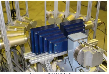
TANGRA-setup consists of a portable neutron generator (ING-27) for producing a continuous beam of 14.1 MeV neutrons, a compact neutron-gamma shielding-collimator assembly and an array of 22 hexagonal NaI (Tl), 10 BGO cylindrical detectors for gamma-ray and neutron spectroscopy in variable configurations. The current configuration utilizes 10 cylindrical BGO gamma-ray detectors (ROMASHA setup), figure 1. While the previous configuration was 22 hexagonal NaI (TI) gamma-ray detectors (ROMASHKA setup) [6]. A 32 channel multi-parametric digital data acquisition system (DAQ) is used for analog signal processing.
Figure 1. ROMASHA Setup
2. Methodology
SHIELD transport codes [2]. D.L. Chichester et al, have optimized the biological shield for D-T neutron generator. The modeling used in these simulations was performed using the MCNP 4C Monte Carlo code [3]. Bergaoui et al. have optimized a neutron radiography system for non-destructive testing that uses 2.45 MeV D-D neutron generator using Monte Carlo N-Particle Transport Code (MCNPX 2.7.0) [4].
This work was applied on ING 27 D-T neutron generator, TANGRA (TAgged Neutron and Gamma RAys) for studying neutron-induced nuclear reactions, ROMASHA setup, Frank laboratory of neutron physics (FLNP), Joint Institute for Nuclear Research (JINR) [5]. The studied parameters were; (1) the shielding-collimator material; three materials were studied; Iron, Tungsten, and Tungsten alloy (90% Tungsten, 7% Nickel, and 3% Iron), (2) the distance between the shielding-collimator assembly’s first plate and the center of the neutron beam; the distance was varied from 0.1 cm to 5.6 cm with 56 bins, while the other distances were set to be functions of the studied distance, and (3) the thickness of shielding-collimator sheets; two thicknesses for each plate were studied 4 cm and 5 cm. The criterion upon which the different collimator parameters were evaluated was based on the ratio between the flux read by the detector and the flux reaching the sample for both neutrons and gammas, such ratio was defined as the Q-value.
1.1 TANGRA Setup
TANGRA-setup consists of a portable neutron generator (ING-27) for producing a continuous beam of 14.1 MeV neutrons, a compact neutron-gamma shielding-collimator assembly and an array of 22 hexagonal NaI (Tl), 10 BGO cylindrical detectors for gamma-ray and neutron spectroscopy in variable configurations. The current configuration utilizes 10 cylindrical BGO gamma-ray detectors (ROMASHA setup), figure 1. While the previous configuration was 22 hexagonal NaI (TI) gamma-ray detectors (ROMASHKA setup) [6]. A 32 channel multi-parametric digital data acquisition system (DAQ) is used for analog signal processing.
Figure 1. ROMASHA Setup
2. Methodology
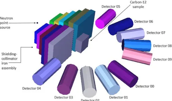
An MCNP5 model was developed for the ROMASHA setup assuming the neutron source to be a point source and the 10 BGO detectors to be cylinders placed at the specified locations in space. Also, the structural material of the experiment has been neglected as shown in figure 2. The structural material was manufactured of stainless steel which is well known to be transparent to neutrons, so they will not affect the readings of the detectors. The experiment upon which the model was validated, was the irradiation of a parallelepiped Carbon-12 sample for one hour to detect the Carbon-12 4.44 MeV characteristic gamma line. The 4.44
MeV peak output from the MCNP5 was fitted to a Gaussian distribution and compared to the experimental output of the 10 detectors (channels), peak energy counts for both experimental results and MCNP5 results were compared as shown in table 1.
Figure 2. ROMASHA Setup MCNP5 Model
Table 1. Validation Results of the ROMASHA Setup MCNP5 Model
Detector Number
Peak Counts of Experimental Results Peak Counts of MCNP5 Results MCNP5 Relative Error Difference Between Experimental and MCNP5
Peak Counts
00 537 548.21 3.63E-02 11.21
01 486 527.32 3.76E-02 41.32
02 387 329.09 4.19E-02 57.91
03 285 287.77 4.71E-02 2.76
04 250 298.69 4.80E-02 48.69
05 232 245.24 5.00E-02 13.24
06 270 237.23 4.89E-02 32.77
07 338 334.69 4.33E-02 3.31
08 423 404.19 3.83E-02 18.81
09 431 420.66 3.61E-02 10.34
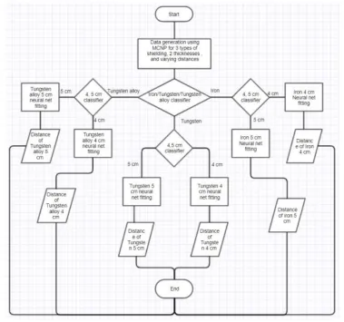
Figure 3. The methodology of Development of the ANNs based Model.
3. Results and Discussion
3.1. Neutrons Q-value CalculationsFigure 3. The methodology of Development of the ANNs based Model.
3. Results and Discussion
3.1. Neutrons Q-value CalculationsThe main reason for calculating the Q-value is to optimize the different collimator parameters in order to achieve the highest Q-value in order to protect the BGO detectors from the radiation damage that can be caused by the neutrons reaching the detector. The neutrons Q-value was calculated for all the proposed materials and the two proposed thicknesses of the collimator with variation in the distance of the first collimator plate from the center of the neutron beam for each BGO detector. Symmetry has been observed between the first five channels and the second five channels, due to the symmetry in their spatial distribution as shown in figure 1. The simple fluctuations shown in figure 4 are due to the variation of the distance mentioned later which affects the differential scattering cross-section of both; the collimator and the sample. In order to simplify the process of analyzing the results, the symmetry mentioned previously was used to compare the different parameters for half the number of channels. It was observed that a five cm thick tungsten collimator gives the highest Q-value for five of the studied channels, and the highest Q-value is at these four channels existed at a distance of the first plate from the center of the neutron beam ranging from zero to 3 cm as shown in figure 4. It was also observed that at a distance ranging from zero to 3
cm the curves have almost identical behavior except that each channel has a higher curve than the previous one. Therefore the distance is chosen for the highest point in the lowest curve, which was found to be 2.3 cm.
Figure 4. Neutron Q-Value versus the Distance between the Shielding Plates for Tungsten Thickness 5 cm Results for Detectors 00-04
3.2. Gamma Q-value Calculations
Like the neutrons Q-value, the gamma Q-value was calculated for all the channels but for a different reason which is to minimize the gamma rays emitting from the inelastic scattering, radiative capture, and gamma Compton scattering of the collimator material to the neutrons and gammas in order to minimize the background radiation reaching the detectors in order to prevent the overlapping of the collimator gamma peaks with the sample peaks in order to facilitate the process of the neutron spectroscopy. The fluctuations shown in figure 5 are due to the variation of the distance between the plates which affects the differential Compton scattering cross-section of both; the collimator and the sample. As in neutron Q-value, it was observed that the highest of the Q-values are achieved when the collimator is Tungsten and its sheets are of 5 cm thick, and the operating distance ranges from 0 to 3 cm. Therefore, the operating distance will be chosen based on the highest Q-value for the lowest channel curve as shown in figure 5, which was found to be 0.7 cm. Since the 0.7 cm distance is not practical, therefore another distance was chosen based on the same methodology which was found to be 1 cm.
0 10 20 30 40 50
0 0.5 1 1.5 2 2.5 3
Q
-Val
ue
Rat
io
Distance (cm)
Tungsten 5 cm Results for Detectors 00-04
Tungsten 5cm ch00 Tungsten 5cm ch01 Tungsten 5cm ch02
Figure 5. Gamma Q-Value versus the Distance between the Shielding Plates for Tungsten Thickness 5 cm Results for the 10 BGO Detectors
4. Conclusion
From the above discussion, it was concluded that the highest Q-Value for the neutrons was that of the collimator made of tungsten of 5 cm thickness and with a distance of 2.3 cm. While that of photons was found to be the same except for the distance of 1 cm. Therefore, the distance to be chosen is the one for neutrons as the higher priority is for protecting the detectors array from neutron radiation damage. One of the problems faced in the optimization process is the huge runtime required for the data generation for such optimization, Future work will include the optimization of the same parameters using the validated Artificial Neural Networks (ANNs) based model described in the methodology.
5. References
1. "Neutron Generators for Analytical Purposes," IAEA, Vienna, 2012.
2. E. S. Konobeevsky, L. N. Latysheva, N. M. Sobolevsky, and R. D. Ili,” Optimizing
the Collimator/Shielding Configuration of the NG-430 Neutron Generator”,
Bulletin of the Russian Academy of Sciences. Physics, 2011, Vol. 75, No. 4, pp. 449–453, 2011.
3. D.L. Chichester and B.W. Blackburn, “Radiation fields from neutron generators
shielded with different materials”, Nuclear Instruments and Methods in Physics
Research B 261 (2007) 845–849.
4. K. Bergaoui, N. Reguigui, C. K. Gary, M. A. Pinstripe and J. T. Cremer, "Design, testing and optimization of a neutron radiography system based on a Deuterium-Deuterium (D–D) neutron generator," Journal of Radioanalytical and Nuclear Chemistry, 2013.
5. I.N. Ruskov, Yu.N. Kopatch, V.M. Bystritsky et al., TANGRA-Setup for the Investigation of Nuclear Fission induced by 14.1 MeV neutrons. Physics Procedia, 64 (2015) 163-170.
6. Skoy V.R., Kopatch Yu.N., Ruskov I., A versatile multi-detector gamma-ray spectrometry system for investigation of neutron induced reactions. 21st International Seminar on Interaction of Neutrons with Nuclei, ISINN-21, 20-25 May 2013, Alushta, Ukraine, pp. 242-248.
0 100 200 300 400 500 600
0 0.5 1 1.5 2 2.5 3
Q
-Val
ue
Rat
io
Distance (cm)
Tungsten 5 cm Thickness Results for the 10 Detectors
Channel 00 Channel 01 Channel 02 Channel 03 Channel 04