Nguyen Van Vu a and Jan Kracik
Department of Power Engineering Equipment, Faculty of Mechanical engineering, Technical University of Liberec, Czech Republic
Abstract. This paper presents progress of evaluation existing ejector of previous work with different gases, included real gas. This work was done by the Ansys simulation tool. The paper also discussed about the two solvers used for simulating real gas difluoromethane (R32). The results showed that entrainment ratios are almost not influenced by different gases but by the working conditions. Secondly, the solver pressure-based can obtain comparable results with the density-based one, while it is much more stable and solution converges faster than the density-based.
Keywords: difluoromethane, real gas, ejector, entrainment ratio, pressure-based, density-based
1 Introduction
Low-grade energy ejector refrigeration system (ERS) drew great attention because of its simplicity and the ability to use low energy sources that other while wasted, such as solar, geothermal, waste energy from plants. The most essential part of this system is the ejector; design of ejector decides the performance of the system.
Thanks to many advantages of CFD, it has been used widely in many areas and has been proved as a power tool for research and development [1][2][3]. CFD is very handy for analysis ejector because CFD simulation can give detail picture about almost every property the supersonic flow, which neither mathematical calculation, nor experimental measurement can do. Moreover, the experimental setups are quite expensive and can analyse only a limited number of flow conditions. CFD simulation offers all characteristic of simulated fluid at once. We can obtain detail, yet complete picture of the subject we study with CFD simulation.
Come to study ejector, most researchers concern about one working fluid, it can be either water vapor [4], air as ideal gas [5], or R134a [6], etc. Apparently, there is no paper mention about the performance of an ejector with different working fluid. Therefore, with this paper, I would like to do a quick comparison between fluids.
Likewise, as far as I know, there is no paper talked about the flow simulation within ejector of real gas, which is high compressible, supersonic flow with shock waves. Hence I try to do so and give a comparison with ideal gas model to see if it worth simulating real gas model. Some engineering problems involve fluids that do not behave as ideal gases. For example, at very high-pressure or very low-temperature conditions (for example, the flow of a refrigerant through a compressor) the flow cannot typically be modelled accurately using the ideal-gas assumption.
There are very few papers on difluoromethane (R32) as refrigerant for ERS. R32 has very good thermo-physical properties as well as good thermal conductivity and low viscosity [7]. It is a perfect substitute for R410a, which is very common in refrigeration applicants but is being phased out because of it high global warming potential (GWP). GWP index of R410a is 2088 while R32 is 675, more than three times higher. In near future, R32 is very attracting refrigerant because of its properties.
2 Model approach
2.1 Ejector model
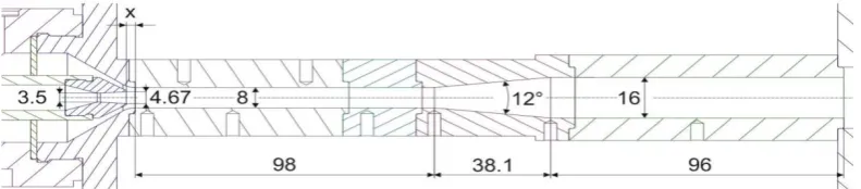
This is a continuation of the work [8]. J. Kracik made a detail numerical and experimental study about relationship of primary pressure and entrainment ratio (ER) of ejector. This is a great ejector model, since it can obtain the ER as high as 0.82, one of the highest values of ER that have been reported. Kracik used air – ideal gas as working fluid. Different values of nozzle exiting position (NXP) were tested. And at the NXP = 3 mm and the following working conditions: 𝑝𝑝𝑝𝑝= 3 bars, 𝑝𝑝𝑠𝑠 and 𝑝𝑝𝑏𝑏= 0 (pressure of primary, secondary and total flow, respectively) delivered the best agreement between CFD simulation and experimental measurement. Accordingly, I used this setup to verify my numerical model.
Fig. 1.: ejector geometry (dimensions in mm) [8]
2.2 Solver setup
Because the flow inside the ejector is high velocity, high compressible, the density-based solver was chosen (the pressure-based solver also used for comparison). Steady flow was selected. Second order upwind scheme was used for all calculations.
In a research on ejector for refrigeration system by CFD simulation and confirmed by experiment, Ruangtrakoon et al use CFD to study the effect of primary throat nozzle [10], they found that k-ω SST
provided more accurate results than two other turbulence models. Therefore, k-ω SST was chosen as
default model. Mathematical model of two-equations
k-ω SST is already emphasized on flow close to wall [10],
it is not necessary to use wall enhance function.
The density-based implicit solver was selected to solve the governing equations which have been proven to be suitable for a supersonic flow field [1], [10] and the flow was set based on steady-state. The pressure-based coupled solver was used for comparing with the other solver in the work of real gas simulation
Least Square Cell-based gradient is less expensive to compute than node-based gradient and it is also much more superior than cell-based gradient [9]. Therefore, Least Square Cell-based gradient was selected as default for all calculation.
The primary inlet and the secondary inlet were set as pressure-inlet type, the outlet was set as pressure-outlet.
The computational results are compared with available experimental data to assess the accuracy of the numerical results obtained with different turbulence models.
2.3 Working fluid properties
Air, carbon dioxin were used as working fluids. They are ideal gases, called directly from Fluent database. Pseudo difluoromethane R32 was also used as working fluid of the model. The properties of pseudo R32 at room temperature is shown in table 1.
Table 1.Properties of pseudo R32 at room conditions (REFPROP 9.1)
Properties Values
Thermal conductivity, 𝑘𝑘 12.508 (𝑚𝑚𝑚𝑚
𝑚𝑚∙ 𝐾𝐾)
Viscosity, 𝜇𝜇 12.607 (𝜇𝜇 𝑃𝑃𝑃𝑃 𝑠𝑠)
Specific heat capacity, 𝐶𝐶𝑝𝑝 0.84716 ( 𝑘𝑘𝑘𝑘
𝑘𝑘𝑘𝑘∙𝐾𝐾)
Molecular weight, 𝑀𝑀 52.024 𝑘𝑘𝑘𝑘
𝑘𝑘𝑚𝑚𝑘𝑘𝑘𝑘
2.4 Boundary conditions
Boundary conditions of primary and secondary inlet were set as pressure-inlet, the outlet of the ejector was set as pressure-outlet. Temperatures were set to 300 K in all cases. If not mentioned, the default primary pressure was set to 3 bars, secondary pressure (overpressure) was zero and backpressure varied. Ambient pressure was set according to local average value in Liberec, 97000 Pa.
The work used NIST real gas database integrated directly to Ansys Fluent for the calculation. The limitation of this real gas model that matter to this study is: the model assumes that the fluid is either superheated vapor, or supercritical fluid, or liquid. Vapor coexists with liquid (two phase flow) is not supported, which is the most disadvantage of this model.
Pressure-inlet, mass flow-inlet, and pressure-outlet are the only inflow and outflow boundaries available for use with the real gas models.
Note that once the NIST real gas model is activated, control of relevant property evaluations is relinquished to the REFPROP database.
Simulation of real gas is challenging, especially for supersonic flows. As far as I know, there are very few, if any, real gas CFD simulations of ejector explicitly reported. Researchers assumed that ideal gas simulations are able to give sufficient results but ironically, there is no comparison by actual results. There are many limitations of real gas models in Ansys Fluent [9], causing difficulties for simulation of compressible gas with supersonic flow. In previous Fluent versions, it was impossible to use pressure-based solver for NIST real gas models [9]. Recently, Fluent supports both pressure-based and density-pressure-based solver. A comparison of two solvers was made.
The real gas simulations were more time-consuming than the one with ideal gases because the flow modelling of NIST real-gas flow is much more complex than ideal-gas flow. As what I observed from the calculations, the pressure-based solver was converged at least three times quicker and residuals were more stable when compared to the other solver.
3 Results and discussion
The calculations were considered as converged when these criteria were met: (1) residuals got lower than 10−5 (10−4 for real gas model simulation), due to difficulties of convergence), (2) mass fluxes of inlet and outlet flows were stable and they had to satisfy the principle of conservation of mass, the net must lower than 10−6 kg/s. Most of calculations in this study converged when the iterations reached the value of 100 000.
3.1 Verification
A model was created to verify with the work of Kracik [8] at different backpressures (or pressure ratio between backpressure and secondary flow (𝜇𝜇). The numerical results obtained showed some discrepancies, mainly in the off-design region. As we can see in the table 2, the entrainment ratio between experimental and numerical method within the on-design region are good, less than 10% of discrepancies [8]. The results obtained from current work were a little bit higher than the simulation results from Kracik. This can be explained by the
Table 2. Comparison results from Kracik [8] with current work
𝜇𝜇 1 1.1 1.2 1.3 1.4 Experiment [8] 0.774 0.774 0.763 0.714 0.627 CFD [8] 0.839 0.839 0.839 0.839 0.776 Current work 0.838 0.838 0.838 0.838 0.774
3.2 Relation between entrainment ratio and turbulence kinetic energy
The shockwave at the beginning of diffusor section when the backpressure is low, and it headed to primary nozzle as the backpressure increased. Figure 3 showed the contours of ejector’s Mach number at on-design regime. Many researchers claimed that the length of mixing chamber does not significantly affect to performance of ejector [2] [13]. However, it was observed that the length of mixing chamber help stabilize ejector’s entrainment ratio, means the performance remains stable while working pressures change in a limited values.
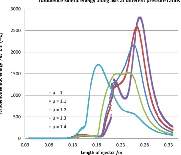
The figure 3 shows the contours of Mach number in mixing chamber area. At the pressure ratio μ of 1, there is a strong shock wave at beginning of diffusor section. Which is corresponding to the highest kinetic energy k with the peak is around 2800 m2∙ s−2 (Fig. 4).
Then with the increase of μ to 1.1, 1.2, 1.3, the flow becomes less intense and no shockwave is seen at ending section of mixing chamber (Fig. 3). This phenomenon is related to the decrease of turbulence kinetic energy. Peak values k also gradually move to the left as μ increases. In spite of those, the ER does not seem to be affected by μ. The flow at the end of mixing chamber at these working pressures is still supersonic with Mach numbers slightly greater than 1.
0 Pa
9700 Pa
19400
29100
38800
Fig. 3.:Contours of Mach number at different pressure ratio
Fig. 4.: Turbulence kinetic energy along axis at different pressure ratios 0
500 1000 1500 2000 2500 3000
0.03 0.08 0.13 0.18 0.23 0.28 0.33
Tu
rb
ul
en
ce
ki
ne
tic
en
er
gy
/
𝑚𝑚
^2
∙𝑠𝑠
^(
−
2)
Length of ejector /m
Turbulence kinetic energy along axis at different pressure ratios
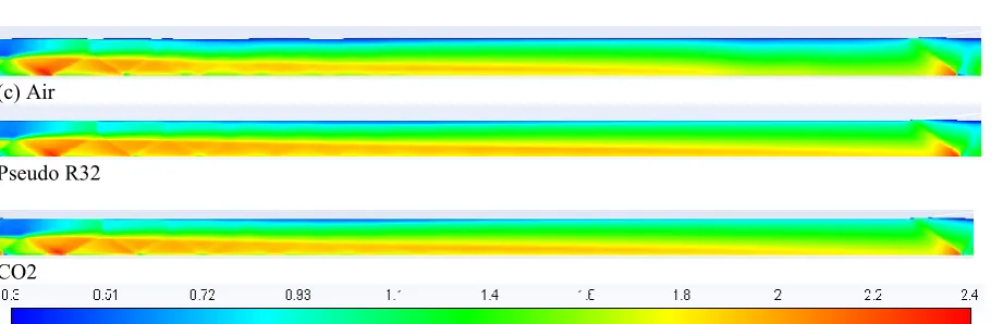
(c) Air
Pseudo R32
CO2
Fig. 5. Mach contours of different ideal gases
There is certainly a relation between critical pressure ratio and positions of peak values k, if μ exceeds critical value, the kinetic energy will transform to turbulence immediately after the primary nozzle. Therefore, the kinetic energy of flow will diminish and entrains fewer medium from suction chamber as consequence. This observation gives good explanation why ER decreases suddenly when μ reaches critical value.
3.3 Entrainment ratio of different gases
In contrast to other characteristics, mass fluxes varied related to the molecular weight but not in linear behaviour, though (Table 3). The entrainment ratios of all gases were remained the same despite of the changes of mass flow rates. From this we can go to a conclusion: the ER is not affected by working gases (at least for ideal gases). It means that changing working fluid does not significantly affect performance of ejector. This is an important point, because basically, we can apply high performance ejector from other researches for our desired working fluids without the needs of geometry reinvestigation as long as they share same working conditions.
Table 3. Mass fluxes of ideal gases
R32 Air CO2
Primary-inlet
(kg/s) 0.0113 0.00861 0.0103
Secondary-inlet
(kg/s) 0.0095 0.00722 0.0086
Outlet (kg/s) -0.0208 -0.01584 -0.0190
Net (kg/s) 2.59E-07 -1.73E-06 -4.49E-06
ER 0.841 0.838 0.835
3.4 Density-based and pressure-based, a comparison of real gas simulations
Historical speaking, the pressure-based solver was developed for low speeds incompressible flows. However, recently it has been reformulated and extended to solve wider range from incompressible to high compressible. This part gives comparison between a well-known solver for shock wave, density-based and
pressure-based, which was believed as unsuitable for high compressible flow.
We would like have the answer for the question: can pressure-based solver give proper results in simulation high compressible with shockwave flow?
Again, all working conditions were remained but working fluid. NIST real gas model of R32 was called in Ansys Fluent. Then two solvers were applied. These calculations were very time consuming.
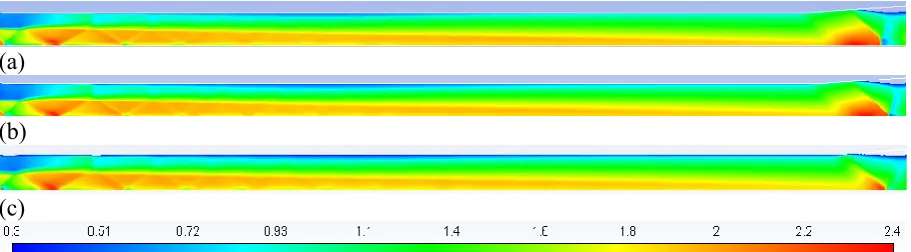
Figure 6 shows contours of Mach number of pressure-based and density-pressure-based solver of real gas model. Both gave very similar results, in graphic and in number. As seen in the figure 6, there are differences in intensiveness of shockwaves at the beginning and at the end mixing chamber but it hard to tell any difference at other aspects. The calculation of the pressure-based solver took significant less time than the other. In addition, density-based solver was very sensitive to working pressure, for example the problem went to divergence just by slightly increase primary pressure, while the pressure based still got convergence. In the figure 7 we can notice that the mass flux of secondary flow in case of pressure-based is slightly greater, leading a higher ER by 1%. From these two points, pressure-based solver is obvious the winner. The pressure-based solver in the latest Ansys Fluent version is mature to solve complex problem such as high compressible with shockwave real gas flow.
Fig. 6. Mach contours of pressure-based (upper) and density-based solver
(a)
(b)
(c)
Fig. 7. Mach contours of pressure-based, real gas (a) and based, real gas (b) solver and ideal gas Pseudo R32 density-based solver
4 Conclusions
The entrainment ratios of ejector are certainly has connection with the turbulence kinetic energy changes inside the ejector, as point out in the last section. It was observed that if there is a jump of the turbulence value right after primary nozzle, means the primary flow at the exiting nozzle is highly turbulent, then the ER is low, off-design regime. In contrast, ejector is on-off-design regime when that primary flow are has low turbulence kinetic energy after exiting primary nozzle for a certain distance. This will give a sense for further detail investigation of relationship of ER and 𝜇𝜇, as well as with the length of mixing chamber.
Secondly, the entrainment ratios of ejector were remained constantly for different working fluids (as least for ideal gases). This means that the performance of ejector is not varied significant with different refrigerants in certain conditions.
Lastly, real gas model simulations seemed to be unnecessary because too much effort was put into it with just a little benefit paid back. And the pressure-based solver (with couple solver) could handle the supersonic
flow of real gas model well enough, unlike traditional belief. Therefore, researchers should consider pressure-based as prior solver even for high compressible, supersonic flow with complex thermo-physical changing such as shock waves to take advantages of this solver (less time-consuming, more stable). Obviously, these observations are needed to verify by further works.
Acknowledgment
1. A. Hemidi, F. Henry, S. Leclaire, J. M. Seynhaeve, and Y. Bartosiewicz, Appl. Therm. Eng., vol. 29, no. 8–9, pp. 1523–1531, (2009).
2. L. Su, “Cfd Simulation and Shape Optimization
of Supersonic Ejectors for Refrigeration” (2015). 3. Y. Allouche, C. Bouden, and S. Varga, Int. J.
Refrig., vol. 39, pp. 186–195, (2014).
4. R. Yapıcı, Energy Convers. Manag., vol. 49, no.
5, pp. 953–961, (2008).
5. A. Hemidi, F. Henry, S. Leclaire, J.-M. Seynhaeve, and Y. Bartosiewicz, Appl. Therm. Eng., vol. 29, no. 14, pp. 2990–2998, (2009). 6. J. Yan, W. Cai, and Y. Li, Renew. Energy, vol.
46, pp. 155–163, (2012).
7. “Service manual for products using R32.”
web access at "http://www.icglimited.co.uk/library/web/1.
Daikin/4. Emura/Emura - Wall Mounted Units (with R32 Refrigerant)/RXJ M2V1B/RXJ M2V1B - Service Manual.pdf"
8. J. Kracik and V. Dvorak, EPJ Web Conf., vol.
143, p. 2056, (2017).
9. ANSYS, “ANSYS FLUENT User’s Guide,” vol.
15317, no. November, p. 2498, (2011).
10 N. Ruangtrakoon, T. Thongtip, S. Aphornratana, and T. Sriveerakul, Int. J. Therm. Sci., vol. 63, pp. 133–145, (2013).
11. S. He, Y. Li, and R. Z. Wang, vol. 13, no. 8, pp. 1760–1780, (2009).
12. N. Van VU, “Study on ejector using CFD
simulation.” (to be published)