Analysis of Tall Structures with and without
Openings in Shear Walls
Amitkumar Yadav1, Dr. Vikram Patil2, Somanagouda Takkalaki 3
1
Civil Engineering, B.R. Harne College of Engineering & Technology, Mumbai, Maharashtra 421503, India
2
Civil Engineering, B.R. Harne College of Engineering & Technology, Mumbai, Maharashtra 421503, India
3
Civil Engineering, B.R. Harne College of Engineering & Technology, Mumbai, Maharashtra 421503, India
Abstract
A Tall Structures with R.C.C frame type are becoming most popular in many of the metropolitan region in India. These type of structures are mostly provided with long shear walls to improve the lateral load resistance system against earthquake and wind loads. A shear wall may contain many openings as per architectural and functional requirements such as horizontal and vertical for circulation purpose. These type of openings in shear walls may affect the overall behavior of the structure. Thus, it is necessary to study the effect of shear wall for various parameters such as Deflection, Bending Moments and Shear Force.
A 3-D analysis of the frame structure with shear wall structure using ETABS for 70 story of building, located in seismic zone III as per IS 1893-2016 (Part2) has been carried out. A Response Spectrum method is adopted for the analysis purpose. The study covers the location and types of openings in shear walls. The structural behavior in terms of deflections, bending moment and shear force are presented and discussed
Keywords: Response Spectrum Method, ETABS version 15, R.C.C Shear Wall, Types of Openings, Base Moment, Shear Force, Deflections.
1. Introduction
Many medium-rise buildings are being constructed in India, using shear walls frame system to provide earthquake resistance to reinforced concrete frames. Shear walls are vertical structural elements that are used as lateral load resistance. These shear walls may have openings for the windows, doors and duct spaces for functional reasons. Framed structures with shear walls are mainly adopted as the structural system for high-rise buildings structures. Introduction of shear wall in a building is a structurally efficient solution to stiffen the building because they provide the necessary lateral strength and stiffness to resist horizontal forces. The size and location of shear wall is extremely critical otherwise, the bending moment at the end of a beam cannot be transferred to the shear wall.
A. Frames
A Rigid R.C frames of rectangular components, beams and columns connected together in the same plane by means of rigid joints. The lateral stiffness of such a frame depends upon the bending stiffness of the column, beams, and connections in the plane. The rigid frame principal advantage is its open rectangular arrangement, which allows freedom of planning and easy fitting of doors and windows.
B. Shear Wall
Shear walls are vertical stiffening elements are designed to resist lateral forces exerted by wind or earthquake. The shape and location of shear wall have significant effect on their structural behavior under lateral loads. These shear wall resist horizontal force because of their high rigidity as deep beams are reacting to shear and flexure against overturning. Shear walls are much stiffer than horizontal rigid frame. Different types of shear wall are i) Based on shape are Box Section, L- section, U- section, W- section, H- section, and T- section. ii) Based on elevation are Short: H/D <1, Squat: 1 < H/D < 3, Cantilever: H/D > 3. Where, H = Total Height of Shear Wall, D = Length of Wall in plan. iii) Based on behavior are Ordinary Shear wall and Special Shear wall.
D. Advantages of Shear Wall
1. It provides adequate strength to resist large lateral loads without excessive additional cost.
2. It provides adequate stiffness to resist lateral displacement within permissible limits, thus reducing risk of non-structural damage.
3. They should be located such a way that they also act as functional walls and do not interfere with the architectural of the building.
4. Shear wall should be placed along both the axis, so that lateral stiffness can be provided in both directions, particularly in the case of square buildings.
5) To avoid torsion effect shear wall should be placed symmetrically about the axis.
E. Function of Shear Wall
The main function of a Shear Wall can be described as follows.
1. Providing Lateral Strength to building: Shear Wall must provide lateral shear strength to the building to resist the horizontal earthquake forces, wind forces and transfer these forces to the foundation.
2. Providing Lateral Stiffness to building: Shear Walls provide large stiffness to building in the direction of their orientation, which reduces lateral sway of the building and thus reduces damage to structure.
2. Objective and Scope
1) The main objective of this work is to avoid the failure of shear wall due to inappropriate location of opening. For satisfying the mentioned objectives following points were studied.
2) Detailed analytical study on opening in shear wall of high rise buildings using ETABS version 15.
3) The present study is limited to analysis of 70 story of R.C.C. Buildings.
4) To determine the effect on structure by providing dual system.
5) To understand effect of opening of two different size.
The Scope of work is limited to
• To understand the behavior of high-rise structure
analytically having openings in shear wall.
• Comparative study of Shear wall with and
without opening.
• Understanding the effect of opening due to
change at different height and location.
• Comparative study of Linear Dynamic analysis of
structure with and without opening.
• To calculate the percentage, change in the values
of various structural parameters like Deflection, Bending Moments and Shear Force, using response spectrum method.
3. Methodology
For the structural analysis there are few methods which is used to understand the behavior of structure. Some of the methods are explain below.
1. Equivalent Static Method: This approach defines a series of forces acting on a building to represent the effect of earthquake ground motion. It assumes that the building responds in its fundamental mode. For this to be true, the building must be low-rise and must not twist significantly when the ground moves. As per this method first the design base shear shall be computed for the building as a whole. Then the base shear shall be distributed to the various floor levels at the corresponding center of mass and finally the design seismic force shall be distributed to individual lateral load resisting elements through structural analysis considering the floor diaphragm action. This method is applicable for regular building with height less than 15m in seismic zone II as per IS code 1893-2016.
2. Response Spectrum Method: The response spectrum represents an envelope of upper bound responses, based on several different ground motion records. For the purpose of seismic analysis, the design spectrum given in IS: 1893 -2016 is used. This spectrum is based on strong motion records of eight Indian earthquakes. This method is an elastic dynamic analysis approach that relies on the assumption that dynamic response of the structure may be found by considering the independent response of each natural mode of vibration and then combining the response of each in same way. This is advantageous in the fact that generally only few of the lowest modes of vibration have significance while calculating moments, shear and deflections at different levels of the building.
base shear is less in Dynamic method as compared to static method. As base shear is less in static than dynamic the displacement will be less in dynamic and also the moment hence dynamic method is used for analysis.
Figure 1: Comparison of Base Shear
4. PROBLEM STATEMENT
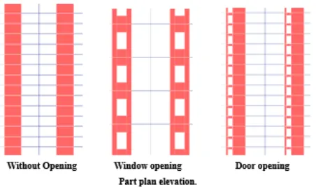
The present study involves the study of structures with and without openings at centrally located and at corners as shown below. The opening size for doors and windows is 1.2m*2.1m and 1.5m*1.5m respectively. The height considered for study purpose is 70 story. The aim of study is to find out the differences in various parameters of structures of an irregular shaped high-rise building using Etabs software is used for analytical study and dynamic wind force are considered as lateral load for study purpose. In this present study two different types of openings and a without opening model will be carried out and the results are compared. The plan dimension is 50m X 50m, and floor to floor height will be 3.0m having varying grade of concrete with rebar grade of Fe 415. The beams and Slabs sizes are remains Constant for all floors i.e. 230*750 mm and 135mm thick respectively.
Figure 2: Floor Plan
Figure3: Part Plan Elevation
Details of building load configurations is as per IS 875 part 1-1987 & IS 875 part 2-1987 as shown in table.
Table 1: Load Configuration
Description Loadings
Self-weight As per Etabs
Floor Finish 1 kN/sq.m
Live loads 2kN/sq.m
wall load 2 kN/sq.m
Live loads Staircase 2kN/sq.m
Table 2: Structural Parameters Building G+70 Floor
5. RESULTS
The structure has been studied for parameters like Bending Moment, Shear Force and Deflection for structure without openings and two different types of openings i.e. door and window As in tall building mostly wind load is governed, so wind load is considered as lateral load for analysis purpose and the result is compared for both in X any Y direction. The models are,
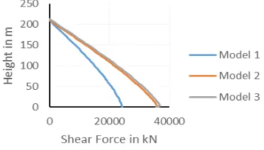
Model 1 is without opening. Model 2 is with window opening. Model 3 is with door opening.
Sr. No Floor No Column
Size mm Shear wall size mm
Grade of
Concrete
N/mm2
1 0-15 700*700 1000 M45
2 16-30 600*600 800 M40
3 31-45 500*500 600 M35
4 45-60 400*400 400 M30
Figure 4. Comparison of Deflection (Wind along X)
Figure 5. Comparison of Deflection (Wind across X)
Figure 6. Comparison of Deflection (Wind along Y)
Figure 7. Comparison of Deflection (Wind across Y) In 70 story building the Deflection in Across X and Across Y is more than Along X and Along Y. Due to opening of
door and window the percentage increase in along X direction is 15.43 % in model 2 and 18.82 % in model 3 as compared to model 1. Similarly, for across X the percentage increase in deflection is 17.45 % in model 2 and 30.86 % in model 3 as compared to model 1 and the percentage increasing in along Y is 10 % in model 2 and 16.68 % in model 3 as compared to model 1. Similarly, for across Y the percentage increase in deflection is 10% in model 2 and 16.13 % in model 3 as compared to model 1.
Figure 8. Comparison of B.M (Wind along X)
Figure 9. Comparison of B.M (Wind across X)
Figure 11. Comparison of B.M (Wind across Y)
In 70 story building the Bending Moment in Across X and Across Y is more than Along X and Along Y. Due to opening of door and window the percentage increasing in along X is 31.95 % in model 2 and 32.99 % in model 3 as compared to model 1. Similarly, for across X the percentage increase in Bending Moment is 32.35 % in model 2 and 37.30 % in model 3 as compared to model 1 and the percentage increasing in along Y is 31.97 % in model 2 and 33.31 % in model 3 as compared to model 1. Similarly, for across Y the percentage increase in Bending Moment is 32.29% in model 2 and 37.67 % in model 3 as compared to model 1.
Figure 12. Comparison of Shear Force (Wind along X)
Figure 13. Comparison of Shear Force (Wind across X)
Figure 14. Comparison of Shear Force (Wind along Y)
Figure 15. Comparison of Shear Force (Wind across Y)
In 70 story building the Shear force in Across X and Across Y is more than Along X and Along Y. Due to opening of different sizes the percentage increasing in along X is 31.95 % in model 2 and 32.99 % in model 3 as compared to model 1. Similarly, for across X the percentage increase in Shear force is 29.06 % in model 2 and 29.65 % in model 3 as compared to model 1 and the percentage increasing in along Y is 29.71 % in model 2 and 31.54 % in model 3 as compared to model 1. Similarly, for across Y the percentage increase in Shear force is 29% in model 2 and 29.07 % in model 3 as compared to model 1.
6. CONCLUSIONS
Based on the results it can be concluded that
1. It is observed that deflection, Bending Moment,
and Shear Force increases as the size of opening increases in Shear wall.
2. Deflection, Bending Moment, and Shear Force is
observed more in model 3 which has more area of opening which a type of door is opening.
3. A maximum percentage for deflection is observed
4. The Deflection exceeds the permissible limits for wind in Across X direction.
5. Results of analysis in Across X and Y direction is more than in Along X and Y.
6. Hence it can be concluded that the opening in
shear wall should be avoided or it should be of minimum size and number as the height of structure goes on increasing for tall structures.
7. REFERENCES
Research paper
1] M. Shariq, H. Abbas, H. Irtaza, M. Qamaruddin , “Influence of openings on seismic performance of masonry building walls, Journal of Building and Environment Engg, Vol 43, March 2007, PP. 1232–1240
2.] G. Ozpalanlar, “Evaluation of Earthquake Response Analysis Methods for Low-Rise Base Isolated Buildings” World Conference on Earthquake Engineering, oct.2008. 3] Hamdy H. A. Abd-el-rahim, “Influence of Requisite Architectural Openings in Shear Walls Efficiency” Journal of Engineering Sciences, Vol. 38, March, 2010. PP. 421-435 4] Vinayak Kulkarni, Swapnil Cholekar, Hemant Sonawadekar,“Effect of openings of shear wall in high rise buildings” Int. Journal of Applied Sciences and
Engineering Research, Vol. 3, May2014, PP. 776- 781
5] Pooja Hegde, “ Effect of Base Opening in Reinforced Concrete Shear Wall” The International Institute for
Science Technology and Education” Vol. 6 2014.
6] Vishal A. Itware, Dr. Uttam B. Kalwane “Effects of Openings in Shear Wall on Seismic Response of Structure”
Int. Journal of
Engineering Research and
Applications, Vol. 5, Issue 7 ( Part - 1) July 2015, 41-45 7] Bhruguli H. Gandhi, “Effect Of Opening On Behavior Of Shear Wall” International Journal For Technological
Research In Engineering, Vol. 3, Dec-2015, 875-878
8] Ruchi Sharma , Jignesh A. Amin , “Effects of opening in shear walls of 30- storey building”Journal of Materials
and Engineering Structures, March 2015, 44-55
9] Aarthi Harini, G. Senthil Kumar, “Behavior of R.C. Shear Wall with Staggered Openings under Seismic
Loads” International Journal For Research And
Technology, Vol 2, March 2015, 91-96
10] Anand S. Attal, Jyoti P. Bhusari“Effect of Opening in Shear Wall ” International Journal of Engineering Research, Vol 5, Feb. 2016 , 572-577. 11] Reshma Chavan, “ Effects Of opening in Shear Wall” IORS Journal of Mechanical and Civil Engineering, Vol. 13, Feb-2016, PP. 1-6
12] Aneeket . T. Patil, Sachin B. Kadam, “Behaviour of Multi-storey Building under the effect of Wind and Earthquake for Different Configuration of Shear Wall”
Journal of Civil Engineering and Environmental Technology, Vol. 3, June-2016, PP. 558-563.
13] S. H. Jagadle, “Analysis of Various Thickness of Shear Wall with Openings and Without Openings and their Percentage Reinforcement” International Journal of Research in Engineering, Science and Technologies, Vol. 2 March 2016, PP. 212-218.
14] Swetha K. S, “Effects of Openings in Shear Wall, International ResearchJournal of Engineering and Technology, Vol. 4, May 2017.
15] Mohamed Safeer Kodappana, “Study on Dynamic Behaviour of Shear Wall with Staggered Openings in Irregular R.C. Framed Structures” International Journal of Scientific Research in Science, Engineering and Technology, Vol. 3, April 2017, PP. 561-567.
16] Sruthy K.S., “Effect of Opening On Reinforced Concrete Coupled Shear Wall” International Journal of Science and Scientific and Engineering Research, Vol.8, Nov. 2017, PP.42-51.
I.S. Codes
17] IS456 (2000) - “Plain and Reinforced Concrete – Code of Practice’.
18] IS1893 (2016) Part I, ‘Criteria For Earthquake Resistant Design of Structures’, Bureau of Indian Standards, New Delhi, India.
19] IS 875 Part 1 (2015) -“Code of Practice for Design
Loads (Other than Earthquake) for buildings and Structures “, Part 1- Dead Loads
20] IS 875 Part 2 (2015) -“Code of Practice for Design
Loads (Other than Earthquake) for buildings and Structures “, Part 2– Imposed Loads.
21] IS 875 Part 3 (2015)- “Code of Practice for Design
Loads (Other than Earthquake) for buildings and Structures “, Part 3- Wind Loads
22] IS 13920-2016-Ductile Design and detailing of reinforced concrete structures subjected to seismic forces.
Books
23] U H Varyani – Structural Design of Multistoried Buildings, Second edition, South Asian Publishers – New Delhi, 2002
24] T. Rambhupal Reddy, “Effects of Opening in Shear Wall of Multistoried Building” Indian Institute of technology, June 2006.
url links
Amitkumar B. Yadav Student of B. R. Harne College of Engineering and Technology, Mumbai University.
Dr. Vikram A. Patil Principal and Guide of B. R. Harne College of Engineering and Technology, Mumbai University completed his Ph.D in Structural Engineering from IIT-Roorkee.