Influence of Abrasive Shape on the Abrasion and Phase Transformation of Monocrystalline Silicon
Full text
Figure
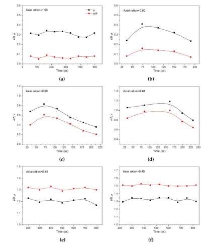
![Figure 3. Displacement of the upper specimen along y-[010] direction vs. time and axial ratio](https://thumb-us.123doks.com/thumbv2/123dok_us/8007288.1330640/5.595.187.409.447.611/figure-displacement-upper-specimen-direction-time-axial-ratio.webp)


Related documents
MTT, invasion and migration assays showed that acidic HCC- derived exosomes significantly increased cell prolifer- ation, migration, and invasion of recipient cells compared with
Throughput, delay, jitter and packet loss performances of various e-learning applications have been analyzed over WiLD networks1. The simulation results suggest that the
(A, left) Pyclograni reveals depressed left kidney suggesting suprarenal mass. (B,
Thanks to its flexibility, the algorithm can be applied to the estimation of Laplace regression with censored data, mixed-effects quantile regression, and other models based on
"Austin Contemporary Visual Arts Association Exhibition," Dougherty Cultural Arts Center, Austin, Texas. Judged by James Melchert, Director, National Endowment for the
or less risk factors for cardiorespiratory disease can be prescribed exercises using heart rate and supplementary exercise intensity measures.. These include the Borg Rate
To clarify how schools may affect students’ resilient outcomes, we formulated and tested four distinct models of the risk factors and resilience- promoting features of schools: (a)
The process for extracting the relevant data for the 2003‐06 period was laborious and
