18th International Conference on Structural Mechanics in Reactor Technology (SMiRT 18) Beijing, China, August 7-12, 2005 SMiRT18-K16-5
SEISMIC ANALYSIS OF LIQUID STORAGE CONTAINER IN NUCLEAR
REACTORS
Zhengming ZHANG
Phone: 86-10-62784809-413
Fax: 86-10-62797136
E-mail: [email protected]
Ming XU
Phone: 86-10-62784824
E-mail:
[email protected]
Shuyan HE
Phone: 86-10-62784823, Fax: 86-10-62797136
E-mail: [email protected]
ABSTRACT
Seismic analysis of liquid storage containers is always difficult in the seismic design of nuclear reactor equipment. The main reason is that the liquid will generate significant seismic loads under earthquake. These dynamic liquid loads usually form the main source of the stresses in the container. For this kind of structure-fluid coupling problem, some simplified theoretical methods were usually used previously. But this can’t satisfy the requirements of engineering design. The Finite Element Method, which is now full developed, is very useful for the structural analysis but not matured for the structure-fluid coupling problem. This paper introduces a method suitable for engineering mechanical analysis. Combining theoretical analysis of the dynamic liquid loads and finite element analysis of the structure together, this method can give practical solutions in the seismic design of liquid storage containers.
Keywords: Liquid storage container, Structure-liquid coupling vibration, Seismic analysis
1. PROBLEMS
Under the action of earthquake or other outside excitation, the liquid storage container will bear dynamic liquid loads besides the inertia forces generated in the structure itself. These loads may generate significant effects on the strength and the stability of the container. Therefore, it is necessary to consider the liquid shaking and impulsion in seismic analysis besides the inertia forces of the structure.[1,2,3]
Although there have well-developed dynamic analysis methods of structure, there is still no proper analysis method on the problem of structure-liquid coupling vibration. The former research method was usually the theoretic analysis. To take account of the dynamic liquid characteristic, a common method is to divide the dynamic liquid loads into convective force generated by the liquid shaking and impulsive force generated by liquid and container moving together (as shown in Figure 1). Detailed introduction can be found in reference [4].
In this paper, an engineering seismic calculation method of the liquid storage container will be introduced. The idea is to use FEA software to establish a FEA model of the container, and calculate the dynamic responses of the structure. The dynamic liquid loads will be simplified to the distributed forces on the container wall through theoretic analysis, and then more reasonable dynamic liquid loads can be obtained.
2. DYNAMIC LIQUID LOADS OF LIQUID STORAGE CONTAINER
To the dynamic liquid loads of the liquid storage container, former researchers had done a lot of theoretic analysis. In this paper, their results will be applied directly. A brief introduction will be given, reference [5] has detailed introduction.
2.1 Theoretic analysis about the dynamic liquid loads
The liquid storage container with column and rectangle shape is mainly discussed here. For the conveniency of theoretic analysis, the container is usually assumed to have rigid wall with ideal liquid inside. Also, it’s assumed that the ground movement has only horizontal component with no rotational component. Under these assumptions, the velocity potential of the liquid satisfies the Laplace Equation :
0
2=
∇
ϕ
(1)the corresponding dynamic liquid loads is:
t
p
∂
∂
−
=
ρ
ϕ
(2)where
ρ
is the liquid density. Figure 1 shows the geometry shape and the coordinate system of the liquidstorage container with column and rectangle shape. Under the assumptions above, the dynamic liquid loads on the sidewall can be solved as:
⎥
⎦
⎤
⎢
⎣
⎡
+
−
=
∑
∞ =10
(
)
(
)
)
,
(
j j w j j wq
y
P
d
t
x
A
t
y
p
(3)where generalized coordinate
q
j(
t
)
is the solution of the equation below:)
(
)
(
~
)
(
~
2
)
(
0 2t
x
t
q
t
q
t
q
j j jj j j+
ξ
ω
+
ω
=
−
(4)In Equation (3) and (4),
x
0(
t
)
is the horizontal component of the ground acceleration during earthquake;j
ξ
is the critical damping ratio of the liquid at thej
th vibration mode shape;)
/
(
)
/
(
)
(
a
h
x
ch
a
y
x
ch
y
P
j j wj
=
;)
/
tanh(
~
2a
h
x
x
a
g
j j j=
ω
; other coefficients are related with the shape of the container. To the column shapecontainer,
A
=
ρ
a
sin
θ
,1
2
2−
=
j jx
d
(x
j is thej
th root of derivativeJ
1′
(
x
)
of the first order Besselfunction
J
1(
x
)
,its value is 1.841, 5.331, 8.536, 11.706, 14.863, etc). To rectangle shape container (planeproblem),
A
=
ρ
a
,x
j=
(
2
j
−
1
)
π
/
2
, 22
j j
x
d
=
. Where,a
is the radius of container if it is columnshape and is the half side length if it is rectangle shape.
The form of Equation (3) is similar to the seismic response of elastic structure, where coefficient
d
jcorresponds to the mode shape participating factor of elastic structure,
P
jw(
y
)
corresponds to the mode shapeAfter known the acceleration
x
0(
t
)
of the ground movement, the time-history of dynamic liquid loads can be calculated by Equation(3). Though it’s an infinite series in form, it’s enough to just get the former few items in practical calculation. In fact, even only the first item of the series is chosen in engineering design, the error will not exceed a few percent.2.2 Application of the response spectra theory
In order to use response spectra to calculate the dynamic liquid loads, Equation (3) is changed to the form below:
(
)
⎥
⎥
⎦
⎤
⎢
⎢
⎣
⎡
+
+
⎟⎟
⎠
⎞
⎜⎜
⎝
⎛
−
−
=
∑
∑
∞ = ∞ = 1 0 0 1)
(
)
(
1
)
,
(
j j w j j j w j j wq
x
y
P
d
x
y
P
d
A
t
y
p
(5)In Equation (5), the first item at the right side represents the impulsive force. It happens when the ground movement
x
0(
t
)
is approximate to instantaneous impulse, the disturb frequency is far larger than the liquidfrequency, so the liquid can be treated as rigid body. It represents the dynamic liquid loads with no surface vibration and has the same time-history with the ground acceleration
x
0(
t
)
. The second item at the right side represents the convective force. It is accumulated by the product of infinite distributed massAd
jP
jw( )
y
andtime function
(
x
0+
q
j)
(
j
=
1
,
2
,
"
)
. It represents the dynamic liquid loads of infinite liquid mode shape. Each time function(
x
0+
q
j)
in Equation (5) represents the absolute acceleration response of a single-degree-of-freedom system with frequencyω
~
j and critical damping ratioξ
junder earthquake. Itsmaximum value is the acceleration spectra value
gk
β
j (k
is the earthquake coefficient, representing themaximum ground acceleration with the unit of gravity acceleration
g
;β
j is the dynamic coefficient,representing the value of acceleration spectra with the unit of the maximum ground acceleration). The maximum value of
x
0 in Equation (5) is the maximum ground accelerationgk
. In this way, it gives the possibility ofusing the acceleration spectra directly.
The
x
0(
t
)
and(
x
0+
q
j)
in Equation (5) are different time functions, their maximum value usually cannot happen at the same time. Based on the same modal superposition method as used in elastic structure, the of Square Root of the Sum of the Squares (SRSS) method can be used to calculate the maximum dynamic liquid loads on the sidewall :(
)
2 1 2 1)
(
)
(
1
)
(
∑
∑
∞ = ∞ =+
⎟⎟
⎠
⎞
⎜⎜
⎝
⎛
−
−
=
j w j j j j w j j wy
P
d
y
P
d
Akg
y
p
β
(6)If only the first mode is considered, Equation (6) can be simplified as below:
To the container with column shape, the maximum dynamic liquid loads on the sidewall is:
(
)
(
)
(
(
)
)
2 1 2/
84
.
1
/
84
.
1
837
.
0
/
84
.
1
/
84
.
1
837
.
0
1
sin
)
(
⎥
⎦
⎤
⎢
⎣
⎡
+
⎟⎟
⎠
⎞
⎜⎜
⎝
⎛
−
−
=
a
h
ch
a
y
ch
a
h
ch
a
y
ch
ga
ck
y
p
wρ
θ
β
(7)
To the container with rectangle shape, the maximum dynamic liquid loads on the sidewall is:
(
)
(
)
(
(
)
)
2 1 2 2 22
/
2
/
8
2
/
2
/
8
1
)
(
⎥
⎦
⎤
⎢
⎣
⎡
+
⎟⎟
⎠
⎞
⎜⎜
⎝
⎛
−
−
=
a
h
ch
a
y
ch
a
h
ch
a
y
ch
ga
ck
y
p
wπ
π
β
π
π
π
π
Where
c
is the structure coefficient. This coefficient can take into consideration the effect that the structure can absorb the earthquake energy after generating plastic deformation. In the usual structural aseismatic design,4
.
0
2
.
0
−
=
c
. It can be increased properly in the design of liquid storage container.Hereinbefore, the SRSS method is used to estimate the dynamic liquid loads. Strictly speaking, the SRSS method should be used in the combination of internal force. That means, the internal loads generated by the impulsive force and every mode shape forces should be calculated separately, then they should be combined by SRSS method and the maximum internal loads can be obtained at last. However, it is too complex to do like this. Considering that the dynamic liquid loads don’t change symbol again and again like the earthquake force generated by each mode shape of the elastic structure, the error from combining forces directly is very small, and the above simplified method can be adopted.
2.3 Selection of the liquid damping ratio
ξ
jand the dynamic coefficient
β
jGenerally speaking, the damping of liquid is much little compared with that of structure. The critical damping ratio of liquid is usually less than one percent to the common liquid storage container. But there is no spectra value less than one percent in the design response spectra. Reference [5] gives a solution:By comparing the acceleration response spectra of different damping recorded in several typical earthquake, it can be known that the response spectra value of zero damping is about 1.5-3 times larger than that of damping ratio
05
.
0
=
ξ
. Considering that the damping of liquid is very small, it can be obtained approximately by enlarging the response spectra value ofξ
=
0
.
05
a time larger.3. SEISMIC ANALYSIS OF LIQUID STORAGE CONTAINER
The fire-protection pool of 10MW High Temperature gas-cooled Reactor (HTR-10) will be taken as the example to introduce the seismic calculation method of the liquid storage container.
3.1 Structure of the pool and its seismic calculation requirements
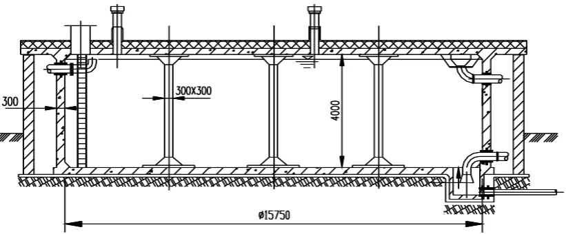
The pool is column shape and its structure is shown in Figure 2. It is made up of the inside reinforced concrete wall, the cover and the outside block wall. The inside diameter of the pool is 15.75m and the height is 4m. There are 9 reinforced concrete pillars in the pool for bearing the cover. There is usually a lot of water in the pool for fire protection.
For a proper aseismatic design, the designer wants to know the detailed distribution of forces in the concrete wall, the pillars and the cover. Traditional theoretical analysis can’t these requirements. The dynamic response of the structure itself, the dynamic liquid loads and the regulations in nuclear codes should be considered together to do the FEA calculation, then the detailed results can be obtained.
3.2 FEA model for the seismic calculation of the pool
The seismic calculation is based on the idea below: Establishing the FEA model of the pool and calculating the dynamic response of the structure using general-purpose FEA software. Then the dynamic liquid loads are simplified reasonably as the outside loads in the FEA model, and the forces generated in the structure can be calculated. Finally, based on the nuclear code, all kinds of forces are combined together.
Figure 3 shows the FEA model of the pool. The model contains the concrete wall, the cover (simulated by shell elements), and the pillars (simulated by beam elements but are not revealed in the figure) of the pool. No water is included in the model. The FEA program applied in this calculation is MSC.NASTRAN, the preprocessor and postprocessor software is MSC.PATRAN.
3.3 Seismic calculation of the pool
Only the calculation under SSE earthquake condition is introduced.
The earthquake excitations are input from the bottom of the concrete wall and the bottom of the pillars. As the regulations of the nuclear code, the structure responses under the earthquake will be calculated in two orthogonal horizontal directions and one vertical direction separately.
Second, the structure responses generated by dynamic liquid loads are calculated. Ignoring the effect of the water shaking to the pillars, the dynamic liquid loads on the concrete wall can be calculated by Equation (7). The parameters in equation (7) are:
k
=
0
.
34
because the maximum ground acceleration of the bedrock of HTR-10 is 0.34g;β
1=
6
.
1
to take the double peak value of the spectra with damping ratio 0.05 as the peak acceleration of water;c
=
0
.
4
is chosen conservatively; anda
=
7
.
875
m
is the pool radius andh
=
4
m
is the pool height.
The wave caused by water shaking will generate dynamic liquid loads on the cover, but there still haven’t any good method to deal with it. Reference [6] points out that the force on the cover generated by liquid shaking can reach
1000
Kg/m
2. As a conservative approximation,1000
Kg/m
2 will be taken as the dynamic liquid force on the cover.Then, bringing the dynamic liquid forces into the model in two orthogonal horizontal directions, the stress distribution in the structure can be calculated separately. The dynamic liquid loads caused by vertical earthquake are very small and is not considered here.
At last, the stress components are combined together. The interior forces of the structure in the same direction are superimposed linearly, including the interior forces caused by static water pressure. Then the interior forces in three directions are combined by the SRSS method, and the interior forces in every parts of the pool can be obtained at last.
Table 1 gives parts of the calculation results.
Table 1. Seismic calculation results of the fire-protection pool (maximum value)
Parts Shearing force Axial force Moment
Root of sidewall 103.3KN/m 62.8KN/m 53.2KN-m/m
Root of pillars 2.6KN 214.1KN 4.2KN-m
4. DISCUSSION
To the coupling vibration problems between elastic structure and liquid, theoretic calculation can only aims at simple structures. The method introduced in this paper can combine theoretic analysis and FEA calculation together, so it can satisfy the aseismatic requirements of engineering problems with more complex structures.
The deformation of the container wall is not considered in this method. For most engineering problems, the structural deformation caused by dynamic liquid loads is really small, so this approximation will not introduce large error.
A traditional engineering method to deal with the coupling vibration problems between structure and liquid is to equal the liquid to the additional mass in the structure. When the impulsive force of the dynamic liquid is large, this method is suitable. But for a container with flat structure as the example in this paper, the convective force of the dynamic liquid is rather large, the additional mass method will cause large error.
The response spectra method is adopted in this paper to calculate the structure response and the liquid is taken as loads, the change of the natural frequencies of the structure caused by the liquid is not considered. This will cause some error, but to the example in this paper, the pool has a cover and the radius-to-height ratio is large, so the lower mode shapes of the structure are mainly the vibration of the cover and the vibration of the sidewall is small. The dynamic liquid mainly affects the vibration of the sidewall, so the liquid will not affect the lower order natural frequencies of the structure significantly. Considering that the lower mode shapes are the most important factors that affect the earthquake responses of the structure, the method used in this paper will not introduce large error in the calculation of the earthquake response of the structure.
REFERENCES
[2] GB50267-97. Chinese national standard, Code for seismic design of nuclear power plant.
[3] ASCE 4-86. Seismic Analysis of Safety-Related Nuclear Structures and Commentary on Standard for Seismic Analysis of Safety Related Nuclear Structures.
[4] N.J.I. Adams. Seismic Design Rules for Flat Bottom Cylindrical Liquid Storage Tanks. Int. J. Press. Ves. & Piping 49(1992), p61-95.
[5] Ju Rong-chu, ZengXin-chuan. Elastic Structure-liquid coupling vibration. Beijing, 1983.
[6] HAF J0002. Chinese nuclear safety documentations, Seismic design for nuclear facilities containing limited radioactivity.