THE BENCHMARK PROJECT IRIS ON MISSILE IMPACTS ON
CONCRETE CONTAINMENT STRUCTURES: MODELLING
APPROACH & ANALYSIS RESULTS OF JRC
O.Martin1, V.Centro2, T.Schwoertzig2
1
European Commission, Joint Research Centre – Institute for Energy, Petten, THE NETHERLANDS
2
Altair Engineering France, Antony, FRANCE E-mail of corresponding author: [email protected]
ABSTRACT
This paper describes the modelling approach and major results of the numerical analyses performed by the Joint Research Centre (JRC) – Institute for Energy (IE), Petten, The Netherlands and Altair Engineering France within the benchmark project “Improving Robustness Assessment Methodologies for Structures impacted by Missiles (IRIS)”. The benchmark project was initiated and carried out within the “Subgroup on Concrete” of the “Working Group on the Integrity and Ageing of Components and Structures (WG IAGE)” of the Nuclear Energy Agency (NEA) of the OECD and lasted the complete year of 2010. Within IRIS each participant was requested to perform numerical analyses on three rather different missile impact tests (two flexural failure tests and one punching shear test) in which missiles were impacted into reinforced concrete slabs. The two flexural failure tests were the Meppen-II-4 Test and a new flexural failure test performed at VTT. The punching shear test was a new missile impact test performed at VTT during the benchmark project. The objective of the numerical analyses was to investigate to what extend they are capable to predict the outcome of these tests. The FE analyses presented in this paper were carried out using complete three dimensional models with Lagrangian meshes for concrete slabs and missiles.
The deformation behaviour of the missiles in all three tests could be predicted accurately by the FE analyses. The slab behaviour was more difficult to predict. The punching through of the missile in the punching shear test at VTT could not be predicted, but scabbing pattern and shear cone inside the slab were estimated quite accurately. Cracking and damage patterns could be well predicted for all three tests, where as the prediction of magnitude and frequency of time series for slab displacements, rebar strains and reaction forces (for Meppen-II-4 Test) varied between the tests. The FE analyses have shown that the prediction of the outcomes of punching shear test is more difficult than for a flexural failure test and that the outcomes of flexural failure tests can be predicted with quite some accuracy with today’s FE codes.
INTRODUCTION
This paper describes the modelling approach and major results of the numerical analyses performed by the Joint Research Centre (JRC) – Institute for Energy (IE), Petten, The Netherlands and Altair Engineering France within the benchmark project “Improving Robustness Assessment Methodologies for Structures impacted by Missiles (IRIS)”. The benchmark project was initiated and carried out within the “Subgroup on Concrete” of the “Working Group on the Integrity and Ageing of Components and Structures (WG IAGE)” of the Nuclear Energy Agency (NEA) of the OECD and lasted the complete year of 2010. Within IRIS each participant was requested to perform numerical analyses on three different missile impact tests in which missiles were impacted into reinforced concrete slabs. The three missile impact tests were one test of the Meppen Slab Tests [1-5] and two new missile impact tests performed at the Technical Research Centre of Finland (VTT) in spring 2010 [6, 7]. The objective of the numerical analyses was to investigate to what extend they are capable to predict the outcome of these tests.
THE MISSILE IMPACT TESTS OF THE IRIS BENCHMARK PROJECT
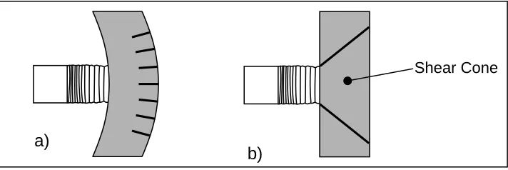
concrete slab, forming the so-called “shear cone”. If the shear stresses are excessively, high the shear cone may be punched out of the concrete slab. Both failure mechanisms are normally accompanied by scabbing (fall off of concrete particles on the backside of the slab, to a considerable extent at punching shear failure and to a smaller extent at flexural failure.
Fig. 1: a) Flexural failure and b) punching shear failure.
a)
b)
Shear Cone
The Meppen Slab Tests is a series of missile impact tests that were performed in the 1970s and early 1980s near the German town of Meppen to investigate the safety of concrete containment buildings of German nuclear power plants (NPPs) against the impact of military aircrafts [1-4]. In the second series of those tests steel pipes resembling the hull of military aircrafts were impacted against reinforced concrete slabs of the dimensions 6.5m × 6m × 0.7m. Each concrete slab had a layer of vertical and horizontal reinforcements at its front and backside surface
respectively and transverse reinforcements to connect the two [2-5]. In the 4th test of the 2nd series of the Meppen
Slab Tests, hereafter referred as the Meppen-II-4 Test, a missile with a mass of 1016kg and an initial velocity of 247.7m/s was impacted against the above described concrete slab. The Meppen-II-4 Test is a flexural failure test. Because of this and the increased values for mass and initial velocity of the missile compared to the other tests of the
2nd series it was chosen for the IRIS benchmark project.
The two missile impact tests performed at VTT are a flexural failure test [6], hereafter referred to as VTT-IRSN Flexural Test, and a punching shear test [7], hereafter referred to as VTT-CNSC-VTT-IRSN Punching Shear Test. In the VTT-IRSN Flexural Test a thin walled steel pipe with a mass of 50.5kg and an initial velocity of 110m/s was impacted against a reinforced concrete slab of the dimensions 2.1m × 2.1m × 0.15m with layers of vertical and horizontal reinforcements at its front and backside and transverse reinforcements between the two [6]. The concrete slab was simply supported along lines of 2m length parallel to the edges both on the front and backside of the slab.
In the VTT-CNSC-IRSN Punching Shear Test a hard missile (steel pipe of 10mm thickness filled with lightweight concrete and having a solid steel dome) of a total mass of 47kg and initial velocity of 135m/s was impacted into a reinforced concrete slab of dimensions 2.1m × 2.1m × 0.25m with layers of vertical and horizontal reinforcements at its front and backside respectively, but no transverse reinforcements [7]. The concrete slab was simply supported along lines of 2m length parallel to the edges both on the front and backside of the slab.
FE MODELLING APPROACH
Modelling of Concrete Slabs
Fig. 2: FE mesh of concrete slab and beam elements for reinforcements for Meppen-II-4 Test.
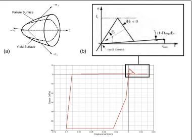
The constitutive behaviour of the concrete is modelled with the non-uniform hardening plasticity model of Han and Chen [9]. It is a Drucker-Prager/Cap model and was designed to model the constitutive behaviour of reinforced concrete under high impact loading. It is the standard material model for reinforced concrete in the FE solver RADIOSS [8]. The constitutive model of Han and Chen is characterised by a tri-axial open failure envelope with a closed yield envelope (cap) inside, which are displayed in Figure 3. The constitutive model allows anisotropic plasticity and hardening, where as the underlying hardening rule is non-uniform. Behaviour in tension and compression are different and failure is achieved either by tensile cracking (brittle fracture) or compressive crushing. Figure 3 shows the principle stress-displacement curve. The constitutive model of Han and Chen accounts for opening and closure of cracks and sensitivity of shear stresses towards different states of compression (pressure sensitivity).
Fig. 3: Concrete material model by Han and Chen [9].
(a) (b)
−σ3
−σ1
−σ2 ξ
Failure Surface
The material model of Han and Chen has in total 24 parameters. In RADIOSS it is implemented in such a way that with five basic material parameters, which are normally available from standard uni-axial material tests, a full description of the constitutive model can be achieved. These five basic material parameters are the initial mass density, Young’s modulus, Poisson ratio, uni-axial compression strength and tensile strength. The remaining material parameters are then estimated from these five basic parameters via standard default ratios or other relationships or simply by taking default values. This is also the adopted approach for all the FE analyses on the three missile impact tests, since only basic material properties were given to the benchmark participants [5-7]. These were initial mass density, Young’s modulus, Poisson ratio, uni-axial compression strength and tensile splitting strength. The tensile strength was calculated from the provided tensile splitting strength and an assumed tensile
tangent modulus of Ht=-3000 MPa (see Figure 3).
For the brick elements directly attached to the beam elements for the reinforcement a different tensile strength value is chosen. The reinforcements inside the real concrete slabs occupy a certain volume. In the FE models the reinforcements are modelled with beam elements, which do not take away volume of the brick elements resembling the concrete. The consequence is an overestimation of concrete that could lead to an unrealistic build-up of crack energy in the concrete. In order to avoid this, the tensile strength of the brick elements directly attached to the beam elements for the rebars are raised by a factor of four. Experience has shown that such factor is adequate.
For the FE model of the VTT-CNSC-IRSN Punching Shear Test an erosion criteria is applied to the elements on the backside of the concrete slab to allow for expected significant scabbing. A tensile failure strain of 50% is assigned to these elements.
For the reinforcements elastic-plastic deformation behaviour is assumed, which are described with Johnson-Cook models in all three tests. Identical hardening curves are assumed for tension and compression for each case. The Johnson-Cook model parameters are derived from the stress-strain curves on the data sheets of the tests [5-7]. Strain-rate effects of the reinforcement are considered when appropriate data was provided in the corresponding data sheets. Strain-rate effects are seen as more important for the missiles. Pre-stressing of reinforcements is not taken into account, since experience from previous analyses has shown that it has negligible effects on the analysis results.
The FE mesh of the reinforced concrete slab for the Meppen-II-4 Test is simply supported on its backside at nodes, which correspond to the mounting points of the concrete slab in the real test. The supporting frame for the concrete slabs of the two VTT impact tests is included in the FE models by defining stripes of rigid walls along the edges of the slab on each side. Kinematic contacts are defined between nodes on the bearing surfaces and the rigid wall stripes. Additionally the rigid wall stripes are connected to springs in order to add damping and transversal deformation of the global steel fame. The stiffness of the springs is adjusted according the impact conditions.
Modelling of Missiles
Lagrangian meshes are used for the missiles in the analyses of all three tests. Thin walled parts like pipes are predominantly modelled with four noded shell elements of reduced integration with some three noded shell elements. Solid parts of the missiles, e.g. the dome and concrete filling of the missile of the VTT-CNSC-IRSN Punching Shear Test, are modelled with linear brick elements of reduced integration. Figure 4 shows two of the meshes for the missiles.
Fig. 4: FE models of missiles for (a) VTT-CNSC-IRSN Punching Shear Test and (b) VTT-IRSN Flexural Test [10].
(a) (b)
Meppen-II-4 Test and the VTT-IRSN Flexural Test. For the rear sections of these missiles and for the entire missile of the VTT-CNSC-IRSN Punching Shear Test no strain-rate effects are considered. For the lightweight concrete filling the same constitutive model with the same material parameters are used as for the concrete of the slab. Only the mass density is reduced in order to accommodate for the mass value of the light-weight concrete given on the data sheets for the VTT-CNSC-IRSN Punching Shear Test. The adjustment of the mass densities of the different sections of the missiles is also applied to the FE models of the missiles of the two flexural tests, so that the mass of each section mesh or the complete mesh matches with the corresponding mass values of the real missiles.
A general contact algorithm based on the penalty method is used for the interaction between missile and concrete slab. All contacts are assumed to be friction free, i.e. Coulomb friction is neglected. Self-contact for the missiles are considered in all the models. Possible interactions between beam elements are considered via edge-to-edge contacts.
RESULTS
Meppen-II-4 Test
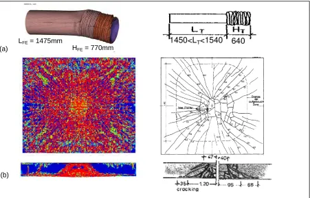
Figures 5 and 6 show a sample of computed results in comparison to the test results. The computed duration of the impact process is 26ms compared to 33ms in the real test and the missile loses all its momentum as in the real test [11]. The FE analysis gives the shape of the missile after the impact correctly and also the computed lengths of folded and unfolded sections are quite accurate (see Figure 5a). Figure 5b shows that the FE analysis resembles the crack pattern of the damaged concrete slab of the real test quite satisfactory. Also the shear cone inside the concrete slab is resembled quite accurately. Figure 6a reveals that the computed displacements of the slab are larger than the measured ones. This could be the result of neglected damping in the FE analysis. The frequency of the time series of the computed displacements is smaller than for the measured ones, but complete agreement in frequencies of computed and measured time series is generally difficult to achieve. This is also visible for Figure 6b showing the time series for one of the reaction forces of the concrete slab. However, there is a good agreement in amplitude of the reaction force.
(a)
(b)
LFE = 1475mm
HFE = 770mm
Fig. 6: More analysis and test results for the Meppen-II-4 Test. K6 -400 -300 -200 -100 0 100 200 300 400 500 600 700
0 0.02 0.04 0.06 0.08 0.1 0.12
Time [s]
F
o
rce [kN]
Test FE Analysis Displacement W6 -70 -60 -50 -40 -30 -20 -10 0
0 0.02 0.04 0.06 0.08 0.1 0.12
Time [s] D isp la cemen t [ m m ] Test FE Analysis
(a) (b)
VTT-IRSN Flexural Test
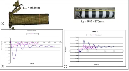
Figure 7 shows some of the computational results in comparison to the test results for the VTT-IRSN Flexural Test. As displayed in Figure 7a the missile is compressed together considerably during the test. The length of the missile after the impact is well predicted by the FE analysis. The crack pattern of the slab given by the FE analysis is similar to the one for the analysis on the Meppen-II-4 Test, but in the test the concrete slab showed only little signs of cracking on its outside surface. Figure 7b shows the computed and measured displacement in the centre on the backside of the slab. The FE analysis gives smaller amplitudes for the displacement compared to the tests, whereas the frequency is overestimated by the computations. This trend could also be observed for slab displacements at other locations. Figure 7c shows the computed and measured strains for one of the rebar locations. Also for the strains in the reinforcements the FE analysis underestimates the amplitude, but overestimates the frequency. A possible explanation could be a too stiff modelling of the slab bearings.
(a)
LFE = 963mm
LT = 940 - 970mm
Displacement W1 -35 -30 -25 -20 -15 -10 -5 0 5
-0.02 0.00 0.02 0.04 0.06 0.08 0.10 0.12 0.14 0.16 0.18
Time [s] Di sp lacem en t [ m m ]
Test FE Analysis
Gauge 12 -0.2 -0.15 -0.1 -0.05 0 0.05 0.1 0.15 0.2
-0.05 0 0.05 0.1 0.15 0.2 0.25
Time [s] Str a in [ % ]
Test FE Analysis
(b) (c)
Fig. 7: Analysis and test results for the VTT-IRSN Flexural Test.
VTT-CNSC-IRSN Punching Shear Test
the expected shear cone inside the slab. The little deformation the missile experienced during the test, is resembled by the FE analysis (Figure 8b). Figure 8c displays the computed and measured strain of one of the rebars inside the slab. The FE model overestimates the strain’s amplitude. This was also observed for the strains of other rebars and slab displacements. The magnitude of the slab displacements was generally significantly overestimated by the FE analyses. All these results show that it is generally more difficult to predict the outcomes of a punching shear test compared to a flexural failure test.
(a)
(b)
Gauge 3
-0.1 -0.05 0 0.05 0.1 0.15 0.2 0.25 0.3
-0.01 0 0.01 0.02 0.03 0.04 0.05 0.06
Time [s]
St
ra
in
[
%
]
Test FE Analysis
(c)
Fig. 8: Analysis and test results for the VTT-CNSC-IRSN Punching Shear Test.
CONCLUSIONS
FE analyses on three rather different missile impact tests have been carried out, two flexural failure test and one punching shear test, using the explicit solver RADIOSS Version 10.0.04. Complete 3D FE models with Lagrangian meshes for concrete slab and missile have been used for the analysis of each test.
The deformation behaviour of the missiles was well predicted by the FE analyses for all three tests. Concerning the slab behaviour the FE analyses on the individual tests delivered different results. The FE analyses for the Meppen-II-4 Test resembled the crack pattern on the outside surface of the slab and inside the slab quite accurately. The magnitude of the computed displacements was generally higher compared to the measured ones, which could be the result of neglected damping inside the FE model. The frequency of the time series of the computed displacements is smaller than for the measured ones, but complete agreement in frequencies of computed and measured time series is generally difficult to achieve. However, there is a good agreement in magnitude of computed and measured reaction forces. In summary the FE analyses on the Meppen-II-4 Test predicted the outcomes of that test quite well.
which is in complete contrast to the analysis of the Meppen-II-4 Test. A possible explanation could be the different boundary conditions for both analyses.
The overall result of the VTT-CNSC-IRSN Punching Shear Test, punching through of missile, could not be predicted by the FE analysis, but the significant scabbing of the concrete slab and shear cone inside the slab were resembled by the FE analysis. The magnitudes of rebar strains and the slab displacements were overestimated by the FE analysis. The computed results show that it is generally more difficult to predict the outcomes of a punching shear test compared to a flexural failure test, but the outcome of flexural failure tests can be predicted quite well with today’s available FE codes.
Possible future work could be to investigate the influence of damping on the computational results of flexural failure tests, especially slab displacements, reaction forces and strains in reinforcements. Concerning analyses on punching shear tests possible future tasks could be an investigation of damage criteria (erosion algorithm) on computed results.
ACKNOWLEDGEMENT
The authors would like to thank the organising committee of IRIS, Mr. Jean-Mathieu Rambach, Mr. Francois Tarallo (both IRSN, France), Mr. Nebojsa Orbovic (CNSC) and Mr. Alejandro Huerta (OECD-NEA), for all their efforts in initiating and organising this benchmark project. The authors would also like to thank Mr. Christian Heckötter from Gesellschaft für Reaktorsysteme (GRS, Germany) and Ms. Arja Saarenheimo (VTT) for kindly providing the results of the missile impact tests.
REFERENCES
[1] Jonas, W., Meshkat, R., Riech, H. and Rüdiger, E., “Experimental Invetsigations to Determine the
Ultimate Bearing Capacity of Reinforced Concrete Slabs subject to Deformable Missiles”, Transactions
of the 5th SMiRT Conference, Berlin, Germany, 1979, paper no. J8/5.
[2] Nachtsheim, W., Stangenberg, F., “Interpretation of the Meppen Slab Tests – Comparison with
parameteric Investigations”, Nuclear Engineering and Design, Vol. 75, 1982, pp. 283-290.
[3] Nachtsheim, W., Stangenberg, F., “Selected Results of the Meppen Slab Tests – State of Interpretation,
Comparison with Computational Investigations”, Transactions of the 7th SMiRT Conference, Chicago, Il,
USA, 1983, paper no. J8/1.
[4] Rüdiger, E. & Riech, H., “Experimental and Theoretical Investigations on the Impact of Deformable
Missiles onto Reinforced Concrete Slabs”, Transactions of the 7th SMiRT Conference, Chicago, Il, USA,
1983, paper no. J8/3.
[5] Gesellschaft für Reacktorsysteme mbH (GRS), “Problem Statement concerning the Meppen-Tests II/4
and II/5”, Data materials for IRIS Benchmark participants, 2010.
[6] IRSN, “Data Synthesis of the VTT-IRSN Flexural Test – Revision B”, Data materials for IRIS
Benchmark participants, 2010.
[7] IRSN, “Data Synthesis for the VTT-CNSC-IRSN Punching Shear Test – Revision B”, Data materials for
IRIS Benchmark participants, 2010.
[8] Altair Engineering Inc., The RADIOSS Manual Version 10.0, Troy, MI, 2009.
[9] Han, D.J., Chen, W.F., “A non-uniform hardening plasticity model for concrete materials”, Mechanics of
Materials, Vol. 4 (3-4), 1985, pp. 283-302.
[10] Martin, O., Centro, V. and Schwoertzig, T., “Numerical Analyses on the Missile Impact Tests performed
at VTT within the Benchmark Project IRIS – Modelling Approach & Preliminary Results”, EUR report – Scientific and Technical Research Series, Office for official Publications of the European Communities, Luxembourg, to be published.
[11] Martin, O., Centro, V. and Schwoertzig, T., “Finite element analysis on the Meppen Slab Tests –
modelling approach & first results”, atw – International Journal for Nuclear Power, 55 (12), 2010, pp.
![Fig. 4: FE models of missiles for (a) VTT-CNSC-IRSN Punching Shear Test and (b) VTT-IRSN Flexural Test [10]](https://thumb-us.123doks.com/thumbv2/123dok_us/1750240.1224409/4.612.133.481.531.648/models-missiles-cnsc-irsn-punching-shear-test-flexural.webp)