Finite Element Analysis of Thin Whitetopped
Pavements
Arthi.S
1, Narasimha.V.L
2, Pandurangan.K
3PG Student, Department of Civil Engineering, Pondicherry Engineering College, Pondicherry, India1 Professor, Department of Civil Engineering, Pondicherry Engineering College, Pondicherry, India2 Associate Professor, Department of Civil Engineering, Pondicherry Engineering College, Pondicherry, India3
ABSTRACT: White topping is defined as Plain Cement Concrete overlay on existing bituminous layer. It provides a new innovative method of rehabilitation which is designed to extend the life to a deteriorated existing bituminous pavement. In this study, edge stresses and deflections of thin Whitetopping overlay for different subgrade condition, modulus of existing bituminous layer, different bonding conditions has been computed by three dimensional finite element method (FEM) using ANSYS software. Temperature stress for different bonding condition was also studied. It is observed that with the increase of thin Whitetopping thickness, concrete tensile stress and deflection decreases for different subgrade CBR value and the modulus of existing bituminous layer. Tensile stress at the bottom of Whitetopping increases by 75% when the interface condition is Unbonded. Irrespective of the bonding condition between the layers, the stiffness of the bituminous layer has little influence on the tensile stress in concrete to the extent of 5% to 10%.Stress due to temperature differential of 15 -20 oC increases to about 10% as compared to a pavement without temperature effects. For the same range of temperature differential, it is seen that temperature stress increases about 80% in unbonded pavement than bonded pavement. It is concluded that bonding at the interface is the most important factor affecting the behaviour of thin whitetopped pavements.
KEYWORDS: Concrete slab, Interface, Contact, Finite Element Model.
I. INTRODUCTION
Whitetopping is a cement concrete overlay constructed on the top of existing bituminous pavement. It is a form of pavement rehabilitation that is designed to extend the life to a deteriorated bituminous pavement. It is used to improve the structural and functional capacity of a roadway. It uses the strength and stiffness of the existing bituminous pavement as a stabilized base course for the new concrete pavement. All the pavements, which have now become badly in condition due for strengthening, are the potential candidates for Whitetopping. As the use of Whitetopping overlay construction is on increase in India, it is necessary to have an improved understanding of the analysis, behavior of whitetopping overlays in order to enhance the rationality of the current design standards and its performance to Indian scenario. There is an increasing trend for using mechanistic approach for design of pavement. Finite element method (FEM) is the most popular mechanistic tool available for analysis. It is a more versatile approach to calculate stresses and deflection developed in pavements due to wheel load configuration.
II. LITERATURE REVIEW
III. FINITE ELEMENT MODELLING
In the present study, a 3- dimensional finite element model for whitetopping pavement system has been developed. The pavement model is a four layer system as shown in fig1consists of concrete layer, existing bituminous layer, subbase layer and subgrade layer. For this, the structural analysis package “ANSYS” has been used. An eight-node solid element (SOLID65) was used to model the concrete slab. The solid element has eight nodes with three degrees of freedom at each node – translations in the nodal x, y, and z directions.3-D brick element SOLID45, having 8 nodes with three degrees of freedom per node translations in the nodal x, y and z directions, are used to model the existing bituminous layer, granular layer and the subgrade. The interface between the concrete slab and existing bituminous layer is represented by contact element TARGE 170 and CONTAC174. SOLID5 is an eight node element is used to find temperature stress. In this analysis, a Mapped mesh was used to get better results. In this study, the model consists of 42592 brick element with 47081 nodes. The bottom of the subgrade was fixed in all directions. All other side faces are restrained in x and z directions.
Fig 1: Four-layer pavement model. DATA USED:
Dimension of the whitetopping pavement model is 4.5mx3.5m. Axle load of 10.2 tonnes is used in analysis of pavement. Table 1 and Table 2 shows the structural and thermal properties of different layers of whitetopped pavements used for finite element analysis respectively.
Table 1: Structural Properties of different layers Layer Thickness
(mm)
Elastic Modulus (N/mm2)
Poisson ratio Density (kg/m3)
Concrete layer 100,150, 200
31623 0.15 2400
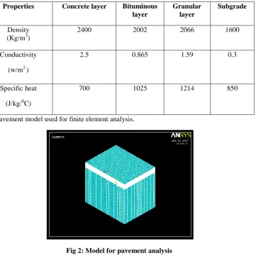
Table 2: Thermal Properties of different layers
Properties Concrete layer Bituminous layer
Granular layer
Subgrade
Density (Kg/m3)
2400 2002 2066 1600
Conductivity (w/m2 )
2.5 0.865 1.59 0.3
Specific heat (J/kg/0C)
700 1025 1214 850
Fig 2 shows the pavement model used for finite element analysis.
Fig 2: Model for pavement analysis
IV. RESULT AND DISCUSSION
Effect of subgrade CBR
(a) (b)
Fig 3: Concrete tensile stress Vs. Subgrade CBR Value (a) Bonded pavement (b) unbonded pavement
Fig 4 shows the variation of deflection with different subgrade CBR values for different interface condition. From the graph, it is seen that deflection decreases with increase in subgrade CBR value.
(a) (b)
Fig 4: Deflection Vs. Subgrade CBR Value (a) Bonded pavement (b) unbonded pavement
Effect of interface bonding condition
The interface bonding condition between Whitetopping and the existing bituminous layer is the most important factor affecting Whitetopping behaviour. Tensile stress increases about 75% for the change in interface condition from fully bonded pavement to completely unbonded pavement. Fig 5 shows the concrete tensile stress for different interface condition. Whitetopping thickness has a more pronounced effect on an unbonded interface condition than a bonded condition.
0 0.1 0.2 0.3 0.4 0.5 0.6
2 6 10 20 100
T en si le S tr ess( N /m m 2 ) CBR(%) 100(mm) 150(mm) 200(mm) 0 0.5 1 1.5 2
2 6 10 20 100
T en si le S tr ess (N /m m 2 ) CBR(%) 100(mm) 150(mm) 200(mm) 0 0.1 0.2 0.3 0.4 0.5 0.6 0.7
2 4 6 8 10 12 20 50
100 D ef le ct io n (m m ) CBR(%) 100(mm) 150(mm) 200(mm) 0 0.2 0.4 0.6 0.8
2 4 6 8 10 12 20 50
Fig 5: Concrete Tensile Stress vs. Interface Bonding Condition for different thickness of Whitetopping pavements with bituminous modulus 1000N/mm2
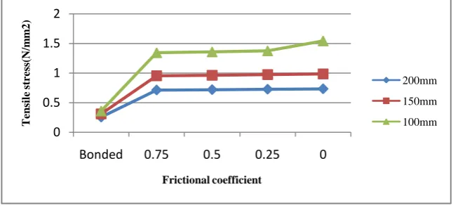
As interface bonding condition plays a major role in the behaviour of whitetopped pavements, partial bonding between the interfaces was also considered in this study. Fig 6 show the concrete tensile stress variation for different frictional coefficients 1 (fully bonded), 0.75, 0.5, 0.25 and 0 (Unbonded), used at the interface for different thickness of whitetopped pavements. It is seen from the graph that the concrete tensile stress decreases with increase in coefficient of friction and decreases with increase in thickness of whitetopped pavement.
Fig 6: Concrete tensile Stress vs. Frictional Coefficient
Effect of Whitetopping thickness
Fig 7 shows the variation of Concrete tensile stress for different Whitetopping thickness. Tensile stress significantly decreases with an increase in TWT thickness. There is 75% increase in concrete tensile stress in unbonded pavement than bonded pavement.
0 0.5 1 1.5 2
Bonded 0.75 0.5 0.25 0
T
en
si
le
st
re
ss(
N
/m
m
2
)
Frictional coefficient
200mm
150mm
100mm 0
0.2 0.4 0.6 0.8 1 1.2 1.4
Bonded Unbonded
T
en
si
le
st
re
ss(
N
/m
m
2
)
Interface Condition
100mm
150mm
(a) (b)
Fig 7: Concrete Tensile Stress vs. Whitetopping Thickness Graph (a) Bonded pavement (b) Unbonded pavement
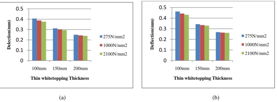
Fig 8 shows the variation of deflection for Whitetopping thickness. Deflection decreases with an increase in Whitetopping thickness. For Unbonded thin Whitetopping the effect of Whitetopping thickness is more pronounced than other conditions.
(a) (b)
Fig 8: Deflection vs. Whitetopping Thickness Graph (a) Bonded pavement (b) Unbonded pavement
Effect of modulus of bituminous layer
Concrete tensile stress versus bituminous modulus plots for different interface condition has been shown in fig 9. There is not much variation in concrete tensile stress with increase in modulus of bituminous layer for both bonded and unbonded pavement. Therefore, modulus of bituminous layer has less effect on different interface condition between concrete overlay and existing bituminous layer.
0 0.1 0.2 0.3 0.4
100 150 200
Te n sil e S tre ss (N /m m 2 )
Thin whitetopping Thickness(mm)
Modulus of Bituminous layer (275N/mm2) Modulus of Bituminous layer (1000N/mm2) Modulus of Bituminous layer (2100N/mm2) 0 0.5 1 1.5
100 150 200
T en si le st re ss( N /m m 2 )
Thin whitetopping Thickness (mm)
Modulus of Bituminous layer (275N/mm2) Modulus of Bituminous layer (1000N/mm2) Modulus of Bituminous layer (2100N/mm2) 0 0.1 0.2 0.3 0.4 0.5
100mm 150mm 200mm
D el ec ti o n (m m )
Thin whitetopping Thickness
275N/mm2 1000N/mm2 2100N/mm2 0 0.1 0.2 0.3 0.4 0.5
100mm 150mm 200mm
D ef le ct io n (m m )
Thin whitetopping Thickness
275N/mm2
1000N/mm2
(a) (b)
Fig 9: Concrete Tensile Stress vs. Modulus of bituminous layer Graph (a) Bonded pavement (b) Unbonded pavement
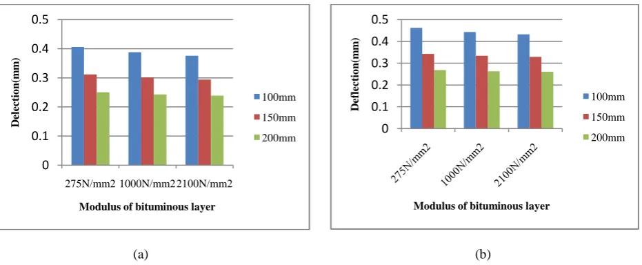
Deflection versus modulus of bituminous plots for different interface condition has been shown in fig 10. With the increase in modulus of bituminous layer, deflection decreases.
(a) (b)
Fig 10: Deflection vs. Modulus of bituminous layer (a) Bonded pavement (b) Unbonded pavement 0
0.1 0.2 0.3 0.4
T
en
si
le
S
tr
ess(
N
/m
m
2
)
Modulus of Bituminous layer
100mm
150mm
200mm
0 0.5 1 1.5
275N/mm2 1000N/mm22100N/mm2
T
en
si
le
st
re
ss(
N
/m
m
2
)
Modulus of bituminous layer
100mm
150mm
200mm
0 0.1 0.2 0.3 0.4 0.5
275N/mm2 1000N/mm22100N/mm2
D
el
ec
ti
o
n
(m
m
)
Modulus of bituminous layer
100mm
150mm
200mm 0
0.1 0.2 0.3 0.4 0.5
D
ef
le
ct
io
n
(m
m
)
Modulus of bituminous layer
100mm
150mm
Contour plot for stress Contour plot for deflection
Effect of temperature stress
The temperature stress for temperature differentials of 150C and 200C on thin whitetopped pavements were examined. Temperature stresses for different Whitetopping thickness have been shown in Fig 11.
(a) (b)
Fig 11: Temperature stress vs. Thickness of Whitetopping Graph (a) Temperature differential 150C (b) Temperature differential 200C.
0 0.5 1 1.5 2 2.5
100 150 200
T
em
p
er
a
tu
re
S
tr
ess(
N
/m
m
2
)
Thin whitetopping thickness(mm)
Bonded
unbonded
0 0.5 1 1.5 2 2.5
100 150 200
T
em
p
er
a
tu
re
st
re
ss(
N
/m
m
2
)
Thin whitetopping thickness(mm)
Bonded
V. CONCLUSION
The objective of this study was to assess the behaviour of thin Whitetopping on existing bituminous pavements for different condition of Subgrade, Thickness of Whitetopping, Modulus of bituminous layer, bonding conditions and temperature differentials. From this study, the following conclusions were made:
1) Interface bonding conditions between thin Whitetopping and the existing bituminous layer are the most important factors that affect thin Whitetopping behaviour. Tensile stress at the bottom of Whitetopping increases by 75% when the interface condition is Unbonded. When the partial bonding was modeled by varying the frictional coefficient by 0, 0.25, 0.5, 0.75 resulted in a considerable drop in tensile stress with increase in coefficient of friction.
2) When the subgrade CBR is very low of 2%, as compared with 100mm thick Whitetopping, tensile stress decreases by 22% and 40% in 150mm and 200mm thick concrete layer respectively for bonded pavement. Similarly, as compared with 100mm thick Whitetopping, tensile stress decreases by 28% and 48% in 150mm and 200mm thick concrete layer respectively for Unbonded pavement. Tensile stresses are observed at the bottom of concrete layer. The tensile stress decreases with increase in CBR value. There is not much variation of tensile stress in bonded pavement but the tensile stress decreases by 25% to 40% in unbonded pavement for CBR value of 100%. Deflections were found to be decreases from 20% to 33% for bonded thin Whitetopping and 24% to 38% for unbonded thin whitetopped pavement. 3) When the thickness is changed from 100mm, 150mm and 200mm, concrete tensile stress decreases by 13% to 28% for 150mm and 200mm respectively as compared with 100mm thick Whitetopping for bonded condition. Concrete tensile stress also decreases by 30% to 48% for for150mm and 200mm respectively as compared with 100mm thick Whitetopping for Unbonded condition. Deflection decreases by 23% to 38% for bonded thin Whitetopping and 25% to 42% for unbonded thin Whitetopping. For Unbonded thin Whitetopping the effect of thin Whitetopping thickness is more pronounced than bonded pavement.
4) Irrespective of bonded and unbonded condition, the stiffness of the bituminous layer has little influence to the extent of 5% to 10% on the behaviour of thin Whitetopping.
5)The temperature stress increases about 80% in unbonded pavement than bonded pavement. The temperature stress also increases about 10% with increase in temperature differential from 15 0C to 20 0C.
REFERENCES
[1] Hossain.M, Muqtadir.A, Hoque A.M, “Three-Dimensional, Finite Element Analysis of Concrete Pavement System”, Journal of Civil Engineer, 1997.
[2] Huang, Y. H. Pavement Analysis and Design. Englewood Cliffs, NJ: Prentice Hall, 2004.
[3] Jundhare.D.R, Khare.K.C and Jain.R.K, “Study of Edge Stresses and Deflections in Whitetopping Overlay on Winkler Foundation”, Indian Geotechnical Conference, 2010.
[4] IRC: 58-2002 “Guidelines for the Design of Plain Jointed Rigid Pavements for Highways (Second Revision)”, Indian Road Congress, New Delhi, 2002.