(An ISO 3297: 2007 Certified Organization)
Vol. 4, Issue 5, May 2015
Design and Development of a Platform for
Processing Bio-Images and Signals Using
Agent Oriented Programming
G.Tholkappia Arasu
1, S. Mathankumar
2, A.Nagappan
3P.G. Student, Department of Biomedical Engineering, VMKV Engineering College, Salem, Tamilnadu, India1
Assistant Professor, Department of Electrical and ElectronicsEngineering, VMKV Engineering College, Salem,
Tamilnadu, India2
Principal, VMKV Engineering College, Salem, Tamilnadu, India3
ABSTRACT: Agent can be defined as a component that, given a goal could act in the place of a user within its domain knowledge. Agents are also called intelligent agents, as intelligence is a key component of agency. Agent oriented approach can be viewed as next step of Object Oriented approach. The project work attempts to demonstrate the concept of developing Multi-Agent platform for processing of Bio-Images and signals. It also demonstrates the concept of developing and deploying agents using JADE – Java Agent DEvelopment framework. The technical goal of this work is to develop a multi agent platform for processing of bio-images and signals aiming at assisting medical practitioners in developing standard examination procedures. If a medical practitioner wants to have an expert opinion about mammogram images and EEG / ECG / EMG of his patient, Generic Agent can be invoked to which he has to specify the SSN (Social Security Number) of the patient, the type of the image and signal and the corresponding data file. The Generic Agent in turn will search for the Specific Agent – Breast image Agent , EEG Agent, ECG Agent, EMG Agent based on the image and signal type on the network and if found, the corresponding information will be passed to the specific agent by the Generic Agent. The result is being sent to the Generic Agent and it stores / updates the result in the Database using the Java Data Base Connectivity. As the agents on the JADE environment run on Threads, the response time is very less which helps the medical practitioner to make a quick diagnosis of mammogram images and signals.
KEYWORDS: Social Security Number, Breast Image Agent, Signal Agent, Java Agent DEvelopment framework
I. INTRODUCTION
Agent can be defined as a component that, given a goal could act in the place of a user within its domain knowledge. Agents are also called intelligent agents, as intelligence is a key component of agency. Agent oriented approach can be viewed as next step of Object Oriented approach. This work attempts to demonstrate the concept of developing Multi-Agent platform for processing of Bio-images using Digital Processing Techniques. It also demonstrates the concept of developing agents using JADE – Java Agent Development framework.
I
nternational
J
ournal of
I
nnovative
R
esearch in
S
cience,
E
ngineering and
T
echnology
(An ISO 3297: 2007 Certified Organization)
Vol. 4, Issue 5, May 2015
Move back and forth
1. Planning
Defining the objectives
Is an agent-based solution the best alternative?
Use another technique
2. Analysis
1 - Use Cases
3. Design
1 - Agent Splitting/Merging/Renaming
2 - Interaction Specification
2 - Initial Agent Types Identification
3 - Responsibilities Identification 3 - Ad-Hoc Interaction Protocol Definition
4 - Acquaintances Identification 4 - Message Templates
5 - Agent Refinement 5 - Description to be Registered/Searched (Yellow Pages)
6 - Agent Deployment Information 6 - Agent-Resource Interactions
7 - Agent-User Interactions
8 - Internal Agent Behaviours
9 - Defining an Ontology
10 - Content Language Selection
4. Implementation & Testing
Unit Testing and Deployment Yes
No
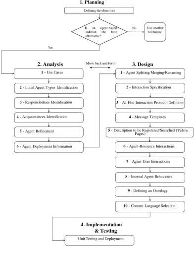
II. METHODOLOGY OVERVIEW
A methodology serves as a guide for the system designer when developing a system. In general, a software development methodology is comprising of:
Figure 2.1. Overview of the Methodology
(An ISO 3297: 2007 Certified Organization)
Vol. 4, Issue 5, May 2015
A set of heuristic rules that support the developer in making relevant choices.
A number of artifacts, i.e. diagrams, schemas or documents representing in graphical or textual form one or more models of the system.
A suitable notation to be used in the artifacts.
A set of patterns that can be applied to solve common situations.
The focus of the work is on the process and the artifacts that are produced and illustrating them. A draft notation is also introduced to be used in constructing these artifacts and, where relevant, some heuristic rules and design patterns are presented. The described process covers the analysis phase and the design phase and is shown in Figure 2.1.
The analysis phase is general in nature and independent of the adopted platform. Conversely, the design phase specifically assumes JADE as the implementation platform and focuses directly on the classes and concepts provided by JADE. Observing Figure 2 . 1, it can be seen that there is strict boundary between the analysis and design phases. Moreover, the methodology is of an iterative nature, thus allowing to move back and forth
between the analysis and design phases and the steps therein. At the end of the design phase, i t i s able to progress straight to the implementation, which is where the actual coding occurs. For the sake of the progress, a question is included (see Figure 1), which initially asks whether to use an agent-based solution or not. If the answer is yes, the analysis phase will be started, while if the answer is no, seek an alternative solution. As mentioned in the Introduction, the decision on whether to adopt an agent-based solution is one which should be made only after consulting the literature, and, if possible, analyzing their problem with respect to some guidelines (such as in [21]). After observing problem domains and cases where an agent-based solution has been implemented effectively, it has been decided to go for Agent oriented Programming for setting up Platform for Processing EEG / ECG / EMG Waveforms.
In the methodology adopted, some assumptions have been made. These include:
The definition of an agent defined in Section 2.1 is assumed.
The JADE platform is the platform of choice for implementation.
There are a relatively small number of agents (less than 10).
The organizational structure of system is static, meaning that no n-emergent behaviour at runtime is not expected, and thus, not considered.
Security is not a concern.
2.2. The Agent based Bio-Image and signal Processing Scenario
The proposed work attempts to demonstrate the concept of developing Multi-Agent platform for processing of Bio- Images and signals. It also demonstrates the concept of developing agents using JADE – Java Agent DEvelopment framework. The agents are trained, intelligent system that is capable of setting up the platform for processing the EEG / ECG / EMG waveforms. The agents themselves communicate with each other in decision making process. The technical goal of this work is to develop a multi agent platform for processing of bio-Images and signals aiming at assisting medical practitioners in developing standard examination procedures.
If a medical practitioner wants to have an expert opinion about Mammogram Images, EEG / ECG / EMG of his patient, Generic Agent can be invoked to which he has to specify the SSN (Social Security Number) of the patient, the type of the signal and the corresponding data file. The Generic Agent in turn will search for the Specific Agent – Breast Image Agent, EEG Agent, ECG Agent, EMG Agent based on the signal type on the network and if found, the corresponding information will be passed to the specific agent by the Generic Agent. For example the EMG medical practitioner wishes to have an expert opinion, the EMG Agent with all necessary information, will look for an EMG Expert System (HINT, DARE, CANDID, MIYOSYS-II). Getting the Expert knowledge, the interpretation will be sent back to the Generic Agent through EMG Agent. The expert opinion will be displayed on the user side as well as it will be stored in
Database by DB Agent for further references
.
III. ANALYSIS AND DESIGN
The analysis phase aims to clarify the problem without any (or minimal) concerns about the solution.
I
nternational
J
ournal of
I
nnovative
R
esearch in
S
cience,
E
ngineering and
T
echnology
(An ISO 3297: 2007 Certified Organization)
Vol. 4, Issue 5, May 2015
Benign
EEG Expert Systems
ECG Expert Systems
EMG Expert Systems Malignant
Performance Analysis
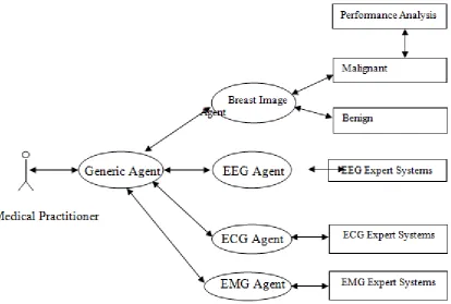
Use cases are an effective way to capture the potential functional requirements of a new system. Each use case presents one or more scenarios that demonstrate how the system should interact with the end user or another system to achieve a specific goal. There are a number of standards for representing use cases. The most popular is the Unified Modeling Language (UML) specification [33], which defines a graphical notation. Though use cases are used extensively by object-oriented practitioners, their applicability is not restricted to object oriented systems, because they are not object orientated in nature [14]. Hence, it is also possible to apply use cases (without modification) to capture the functional requirements of multi-agent systems. Accordingly, the use cases a r e defined, and a use case diagram produced as shown in Figure 3.1.
Figure 3.1. Use case diagram for Multi-Agent System
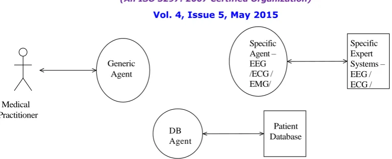
3.2 Step 2: Initial Agent Types Identification
This step involves identification of the main agent types and subsequent formation of a first draft of the agent diagram. The following rules have been adopted in this step:
Add one type of agent per user/device.
Add one type of agent per resource (which includes legacy software).
(An ISO 3297: 2007 Certified Organization)
Vol. 4, Issue 5, May 2015
Generic Agent
Specific Agent – EEG /ECG / EMG/
Medical Practitioner
DB Agent
Patient Database
Specific Expert Systems – EEG / ECG /
EMG
Figure 3.2. Agent diagram for Multi-Agent System after Step 2
1. Agent types: the actual agent types, represented by circles.
2. Humans: people that must interact with the system under development, represented by the UML actor
symbol.
3. Resources: external systems that must interact with the system under development, represented
by rectangles.
4. Acquaintances: represented by an arrow linking instances of the above elements, specifying that the linked
elements will interact in some way while the system is in operation. Note that, at this stage, only acquaintances between agents and resources / humans are shown in the agent diagram (i.e. agent-agent interactions are deferred to a later step). In the agent diagram produced in this step (see Figure 3.2), the agents are acting as transducers, i.e. as an interface between the external/legacy systems/people, and the other agents in the system.
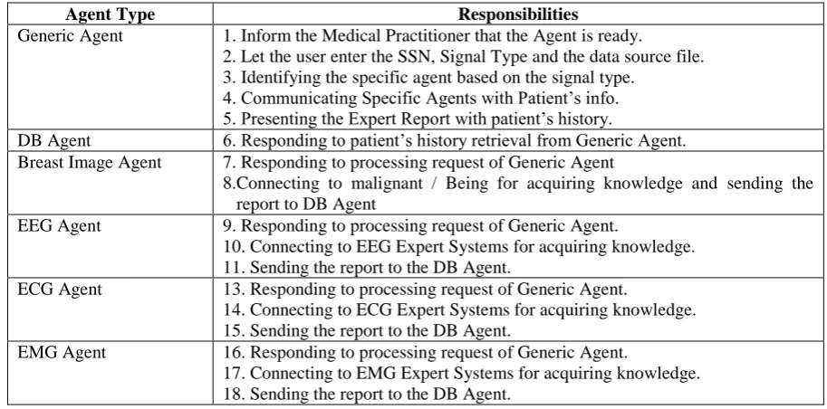
3.3 Step 3: Responsibilities Identification
In this step, for each identified agent type, an initial list is made of its main responsibilities in an informal and intuitive way. The artifact resulting from this process is the responsibility table.
The following rules have been adopted in this step:
Derive the initial set of responsibilities from the use cases identified in Step 1.
Consider the agents where these responsibilities are clearer first and delay the identification of responsibilities for other agents to later steps.
By applying the above rules to the Multi-Agent System Development, the consideration of the Generic agent is initiated and Table 1 is produced.
Table 3.3. Responsibility table for multi-agent system after Step 3.
Agent Type Responsibilities
Generic Agent Inform the Medical Practitioner that the Agent is ready.
Let the user enter the SSN, Signal Type and the data source file. Communicating Specific Agents with Patient’s info.
Present the Expert Report with patient’s history.
3.4 Step 4: Acquaintances Identification
In this step, the focus is on who needs to interact with whom and the agent diagram (Figure 3.1) is updated by adding proper acquaintance relations connecting agents that need to have one or more interactions. The term acquaintance comes from Gaia [35], and is used in the same sense in the proposed system.
I
nternational
J
ournal of
I
nnovative
R
esearch in
S
cience,
E
ngineering and
T
echnology
(An ISO 3297: 2007 Certified Organization)
Vol. 4, Issue 5, May 2015
Figure 3.4. Agent diagram for multi-agent system refined after Step 4
Table 3.4. Responsibility table for multi-agent system updated after Step 4.
Agent Type Responsibilities
Generic Agent Inform the Medical Practitioner that the Agent is ready.
Let the user enter the SSN, Signal Type and the data source file. Identifying the specific agent based on the signal type.
Communicating Specific Agents with Patient’s info. Present the Expert Report with patient’s history.
DB Agent Respond to patient’s history retrieval from Generic Agent
3.5 Step 5: Agent Refinement
In this step, the set of agent types initially identified in Step 2 (see Section 3.2) are refined by applying a number of considerations. These are related to:
Support: what supporting information agents need to accomplish their
responsibilities, and how, when and where is this information generated/stored.
Discovery: how agents linked by an acquaintance relation discover each other.
Management and monitoring: is the system required to keep track of existing agents, or the starting and
stopping of agents on demand.
3.5.1 Support
These considerations are highly dependent on the domain, and hence, it is quite difficult to provide generic indications. Once the Generic Agent is fed with the required details, it in turn searches for the specific agent to pass the required messages. If the specific agent is ready the processing of the signal will be initiated. The refined responsibilities table is presented in Table 3.5.3.
3.5.2 Discovery
In the simplest case, agent discovery can be accomplished by means of proper naming conventions. For example, in the proposed system the processing agents are named after the type of signal it processes – EEG Agent, ECG Agent, EMG Agent.
Adopting naming conventions is very simple and efficient, but has some limitations:
Agent na mes must be globally unique.
Agents which are going to be involved in an interaction must typically be known in advance. This works well provided that it is known in advance that there is one, and only one, such agent.
Assuming naming conventions is typically not very extensible.
Naming conventions may lead to additional work when applied to an agent that can appear and disappear dynamically. The reason being that a naming convention does not provide any presence information, and therefore, addressed agents may not be available when an attempt is made to contact them.
Naming conventions cannot be adopted when different users may start their own agents and choose names Generic
Agent
Specific Agent – EEG /ECG / EMG
Medical Practitioner
DB Agent
Patient Database
(An ISO 3297: 2007 Certified Organization)
Vol. 4, Issue 5, May 2015
themselves. In such cases, there is no guarantee that name uniqueness is preserved.
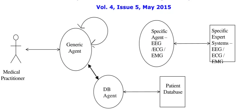
3.5.3 Management and Monitoring
Other agent types can be added to address issues such as monitoring agent faults and restoring them, creation of supporting agents that are needed only under certain conditions, or providing presence information. Having refined the set of agent types, the process is to go back to Steps 2, 3, and 4(Sections 3.2, 3.3, and 3.4, respectively), and iterate until sufficiently detailed descriptions of the agent types, their responsibilities, and acquaintance relations, respectively, are reached. On doing this, with respect to the multi-agent system, the artifacts shown in Figure 3.5.3 and Table 3.5.3 are obtained.
Figure 3.5.3 Agent diagram for multi-agent system refined after Step 5.
Table 3.5.3 Responsibility table for multi-agent system updated after Step 5
Agent Type Responsibilities
Generic Agent 1. Inform the Medical Practitioner that the Agent is ready.
2. Let the user enter the SSN, Signal Type and the data source file. 3. Identifying the specific agent based on the signal type.
4. Communicating Specific Agents with Patient’s info. 5. Presenting the Expert Report with patient’s history.
DB Agent 6. Responding to patient’s history retrieval from Generic Agent. Breast Image Agent 7. Responding to processing request of Generic Agent
8.Connecting to malignant / Being for acquiring knowledge and sending the report to DB Agent
EEG Agent 9. Responding to processing request of Generic Agent.
10. Connecting to EEG Expert Systems for acquiring knowledge. 11. Sending the report to the DB Agent.
ECG Agent 13. Responding to processing request of Generic Agent.
14. Connecting to ECG Expert Systems for acquiring knowledge. 15. Sending the report to the DB Agent.
EMG Agent 16. Responding to processing request of Generic Agent.
17. Connecting to EMG Expert Systems for acquiring knowledge. 18. Sending the report to the DB Agent.
3.6 Step 6: Agent Deployment Information
Another artifact that can be useful to produce is the agent deployment diagram, where the physical hosts/devices agents are going to be deployed are indicated. The agent deployment diagram for the multi-agent system is shown in Figure 6. It should be noted that this diagram is not intended to give any detailed information about deployment (in contrast to the UML deployment diagram, where details such as the communication modes between nodes are given). The sole purpose of the agent deployment diagram is to highlight basic deployment requirements that are referred to during design when applying considerations such as agent splitting and merging (Section 4.1) or when
Generic Agent
Specific Agent – EEG /ECG / EMG
Medical Practitioner
DB Agent
Patient Database
I
nternational
J
ournal of
I
nnovative
R
esearch in
S
cience,
E
ngineering and
T
echnology
(An ISO 3297: 2007 Certified Organization)
Vol. 4, Issue 5, May 2015
considering communication efficiency.
igure 3.6. A
gent deployment diagram for multi-agent system after Step 6.
3.7Design
Once the problem has been clarified to a sufficient level of detail, a move is made from the analysis to the design phase, which aims to specify the solution. There is not a strong boundary between these two phases, and while iterating on the analysis or design, one can move between the two (see Figure 1). Since from this point on, the proposed methodology focuses on the JADE platform (and hence., the constructs provided by it). Carrying out the design phase allows to reach a level of detail that is sufficient enough to have a relatively straightforward transition to the implementation, with the possibility of a significant amount of code being generated. Similar to the analysis, the design phase ha s been carried out by following a number of logical steps, with a certain degree of overlap. The steps in the design phase are discussed in detail as shown in the figure
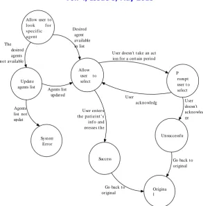
3.7.1Internal Agent Behaviours
The actual job an agent has to do is typically carried out within the agent’s “behaviour(s)”. Hence, in this step, the agent responsibilities are looked up (via the responsibility table) identified in the analysis phase and maped them to agent behaviours. First of all, the following rule has been applied: For a responsibility related to an interaction in the interaction table described in Step 2 of the design phase (Section 4.2), obtain the JADE class implementing the interaction protocol and role selected for that interaction and provide a suitable extension. The responsibilities have been implemented using completely application-specific behaviours. These classes include:
OneShotBehaviour: implementing an atomic task that runs once and terminates immediately.
CyclicBehaviour: implementing a task that is always active, and performs the same operations each time it is
scheduled.
TickerBehaviour: implementing a task that periodically executes the same operations.
WakerBehaviour: implementing an atomic task that runs once after a certain amount of time, and then
terminates.
The State Transition Diagram in Figure 3.7.1 demonstrates that for the responsibilities defined in the analysis phase, there may be many “sub-responsibilities” (unanticipated responsibilities arising from the main responsibilities in the responsibility table) when mapping to agent behaviours (leading to an update of the responsibility table).
Generic Agent
EEG Agent
ECG Agent
EMG Agent
Expert System
-EEG
Expert System - ECG
Expert System - EMG
Medical
Practitioner – User System
(An ISO 3297: 2007 Certified Organization)
Vol. 4, Issue 5, May 2015
Allow user t o loo k fo r specif ic agent Desired agent available in list The desired agents not available in list
User doesn't t ake an act ion for a cert ain period of t ime
Allow user t o select Agent
P rompt user t o select Datfile Updat e
agents list Agents list
updat ed User
acknowledg es prompt User doesn't acknowled ge
prompt aft er cert ain period of t ime Agents
list not updat ed
User enters the patieint’s info and presses t he
"Done" but t on Unsuccessfu
l Syst em
Error
Success Go back t o
original screen
Go back t o original screen Origina l Screen
Figure 3.7.1. State Transition Diagram for “let the Generic agent enters the SSN, Signal Type and Data file name” responsibility.
IV. DEPLOYMENT AND TESTING
I
nternational
J
ournal of
I
nnovative
R
esearch in
S
cience,
E
ngineering and
T
echnology
(An ISO 3297: 2007 Certified Organization)
Vol. 4, Issue 5, May 2015
Fig(a) Original Mammogram image fig (b) Gabor Magnitude Phase
Fig( c ) Gabor orientation field
V. CONCLUSIONS AND FUTURE WORK
The JADE platform is a popular, FIPA-compliant platform for the development of multi-agent systems. However, prior to this, no formal work on bio-images and signal processing had been proposed for the analysis and design of multi-agent systems using the JADE platform. The multi-agent system for processing Bio-Images and signals will help the medical practitioners to have a standard examination procedure. It also helps the medical practitioner to interact with the expert in the field his need in order to make a proper judgment in the diagnosis phase. As the agents on the JADE environment run on Threads, the response time is very less which helps the medical practitioner to make a quick diagnosis of mammogram images and signals. The breast cancer images are classified using of Computer Aided System and the results will be analyzed.
REFERENCES
1. G. Caire and D. Cabanillas, “JADE tutorial: creating and using application specific ontologies”, 2004, see: http://jade.tilab.com/doc/CLOntoSupport.pdf.
2. C. Campo, Directory Facilitator and Service Discovery Agent, FIPA Document Repository, 2002, see: http://www.fipa.org/docs/input/f-in-00070/f-in-00070.pdf.
(An ISO 3297: 2007 Certified Organization)
Vol. 4, Issue 5, May 2015
5. The FIPA AUML Web Site, see: http://www.auml.org/.
6. M. R. Genesereth and S. P. and Ketchpel, "Software Agents," Communication of the ACM, vol. 37(7), 1994. 7. JADE – Java Agent DEvelopment Framework, see: http://jade.tilab.com/.
8. N. R. Jennings, “Agent-based Computing: Promise and Perils,” Proceedings of the 16th International Joint Conference on
Artificial Intelligence (IJCAI-99), Stockholm, Sweden, 1999, pp. 1429-1436.
9. M. Luck, R. Ashri, and M. D’Inverno, Agent-Based Software Development, Artech House Publishers, 2004.
10. M. Luck, P. McBurney, and C. Preist. “Agent Technology: Enabling Next Generation Computing,” AgentLink, 2003, see: http://www.agentlink.org/admin/docs/2003/2003-48.pdf.
11. E. Milgrom (Ed.), “Final guidelines for the identification of relevant problem areas where agent technology is appropriate” (from the MESSAGE methodology), EURESCOM, 2001, see: http://www.eurescom.de/~pub-deliverables/P900-series/P907/D2/p907d2. pdf.
12.The Model – View -Controller, see:http://java.sun.com/blueprints /patterns/MVC-detailed.html. 13. Protégé, see: http://protege.stanford.edu/.
14. S. Paurobally, J. Cunningham, and N. R. Jennings, “Developing agent interaction protocols graphically and logically,” Proceedings of
the First International Workshop on Programming Multi-Agent Systems, Melbourne, Australia, 2003, pp. 45-54.
15. Y. Shoham,“Agent Oriented Programming,”Artificial Intelligence,vol.60(1),pp.51-92, 1993.
16. A.Sturm and O.Shehory, “A framework for evaluating agent-oriented methodologies,” Agent-Oriented Information
Systems, 5th International Bi-Conference Workshop (AOIS 2003), Melbourne, Australia, July 14, 2003.
17. Unified Modeling Language (UML), see: http://www.uml.org/.
18. M. Wooldridge, An Introduction to Multiagent Systems, John Wiley and Sons, 2002.
19. M. Wooldridge, N. R. Jennings, and D. Kinny, “The gaia methodology for agent-oriented analysis and design,” Autonomous Agents and
Multi-Agent Systems, vol.3(3), pp. 285-312, 2000.
20. M. J. Wooldridge and N. R. Jennings “Pitfalls of agent-oriented development,” Proceedings of the 2nd International Conference on
Autonomous Agents (Agents- 98), Minneapolis, USA, pp. 385-391, 1998.