Transactions,SMiRT-23 Manchester, United Kingdom - August 10-14, 2015
Division V, Paper 795
SASSI FLEXIBLE VOLUME SUBSTRUCTURING METHODS FOR
DEEPLY EMBEDDED STRUCTURES; SELECTION OF EXCAVATED
SOIL INTERACTION NODES AND ELEMENT MESHING
Dan M. Ghiocel 1
1Chief of Engineering, Ghiocel Predictive Technologies, Inc., New York, USA
ABSTRACT
The paper presents key aspects of the application of the SASSI Flexible Volume (FV) substructuring to deeply embedded structures, such as small modular reactors (SMR). Different substructuring methods which use different idealizations of the excavated soil dynamic behavior are compared. The investigated SSI models include i) full SMR models, ii) quarter SMR models, iii) SMR massless foundation models and iv) SMR excavation cavity models. Sensitivity studies address the excavation mesh size and mesh nonuniformity. Both uniform and highly non-uniform soil profiles are considered. Comparative SSI results are obtained in terms of the acceleration transfer function (ATF) amplitudes. Based on the presented results, application guidelines of the SASSI substructuring for deeply embedded structures are provided.
SASSI FLEXIBLE VOLUME METHODS
In the SASSI Flexible Volume (FV) substructuring only the free-field soil impedances and the free-field motions are needed for defining the seismic load vector. Both free-field soil motions and impedance functions for embedment soil layers are computed fast using accurate frequency-dependent consistent boundaries for the reflected wave propagation in the infinite soil 3D space. An unique feature of the FV substructuring approach, is that the SSI analysis is performed for the structure dynamically coupled with the excavated soil (the soil removed by the embedment). It should be understood that in the context of the FV substructuring, the wave scattering effects are included by the excavated soil motion. The excavated soil acts as a cavity within the soil deposit. If the excavated soil motion is predicted inaccurately, then this could directly affect the wave scattering effects, and further the SSI responses.
The FV substructuring methods, such as FV, SM and MSM are different by how the excavated soil is modelled. Therefore, these methods differ in the level of approximation introduced for capturing the excavated soil behaviour under the free-field soil excitation. The difference in the excavated soil modelling introduced by the different selections of the SSI interaction nodes impacts directly on the kinematic SSI (or wave scattering) solution accuracy.
The SM assumes that the interaction nodes are defined only by the nodes at the interface of the excavated soil with the surrounding soil deposit. This implies that SM uses correct equations of motion only for part of the excavated soil nodes that are the interaction nodes at the interface of the excavation model with the surrounding soil deposit. For the rest of the excavated soil equations that correspond to the non-interaction nodes, the free-field soil seismic load and impedance terms are neglected. As a result of the approximate SSI modelling for a number of equations of motion in the excavated soil at the non-interaction nodes, the excavated soil motion includes a number of spurious vibration modes. These spurious modes can be excited by the short wavelength components in the mid and high frequency ranges. For softer excavated soils there is a larger number of spurious modes in the mid-high frequency range of engineering interest than for stiffer soils. Thus, the SM solution depreciates faster for the softer excavated soils and higher frequency seismic excitations. For low frequency inputs, since the wave scattering effects are reduced, the effects of the approximate modelling and prediction of the excavation soil dynamics is much less important, and, therefore, SM is reasonably accurate for such situations.
MSM, in addition to the interaction nodes defined by SM at the FE model-far-field soil interface, MSM includes as interaction nodes also the excavation nodes at the ground surface. Including the surface nodes as interaction nodes greatly improves the excavated soil response accuracy since the scattered surface wave motions are captured much more accurately. It was shown that MSM provides a great increase in the accuracy in comparison with SM. MSM appears an accurate and robust method for typical nuclear islands for the frequency ranges of interest in practical applications (Gutierez, 2011, Ghiocel et al, 2013). However, for deeply embedded structures such as SMRs, the MSM accuracy breaks down (Ghiocel, 2013, 2014).
For deeply embedded structures, additional excavation internal nodes need to be defined as interaction nodes at different depths within the excavation. These internal interaction nodes are able to capture the existence of significant scattered body waves and soil layer interface waves within deep excavation “pools”. For getting an appropriate modelling, the additional excavation internal nodes defined as interaction nodes should be defined on continuous horizontal surfaces within the excavation. The number of required layers of internal interaction nodes within excavation depends on the soil column properties. This defines the “Fast Flexible Volume” (FFV) method. The FFV method defines as interaction nodes all the excavation outer surface nodes plus additional horizontal layers of the excavation internal nodes. Thus, the FFV excavation model represents a more refined reduced-order model including internal nodes than the MSM excavation model. The spacing between the internal interaction node layers is an important parameter for the FFV method.
The wave scattering effects could be also affected by the excavation mesh size and mesh nonuniformity. Next section includes few case studies that address the excavation volume mesh issues for deeply embedded structures.
CASE STUDIES
and mesh nouniformity, iii) use of excavation cavity models and massless foundation models to assess wave scattering effects, and iv) use of quarter SSI models instead of full SSI models to validated the SSI solution accuracy. All SSI analyses were performed using the ACS SASSI software (2015).
Substructuring Methods
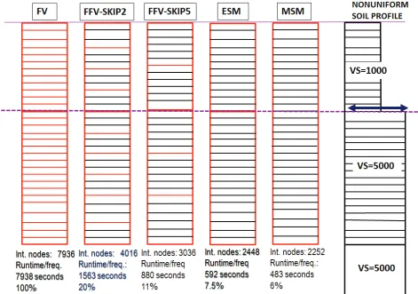
Figure 1 shows the SMR massless foundation model that was used for investigating the accuracy of different FV substructuring methods. The generic SMR foundation model is a shell FE model with an overall size 120ft x 100ft x 100ft (H x L x W). The basement shell and the soil excavation mesh size is 4ft x 8ft x 8ft (4ft vertical and 8ft horizontal). The basement includes 30 embedment soil layers, down to a foundation depth of 120 ft. Figure 2 (right) shows the two geological layer soil profile that was considered. The top soft soil layer with a Vs = 1,000 fps goes down to a depth of 48ft. Below the 48ft depth, the hard soil layer with a Vs = 5,000 fps (outcrop) extends down to an unlimited depth. The seismic input control motion was defined at the top of the hard soil layer considered to be the outcrop.
For this study five scenarios of modelling the excavated soil were considered, as shown in Figure 2 (left). These five modellings were defined using four types of SSI substructuring methods with different selection of interaction nodes (plotted with red lines): i) Flexible Volume (FV) method, as the reference method, ii) Fast Flexible Volume (FFV) method with two different sets of excavation internal interaction nodes, iii) Modified Subtraction Method (MSM) and iv) Extended Subtraction Method (ESM).
The FFV method was considered with two modelling options as illustrated in Figure 2 (left): i) FFV-Skip2, for which the excavation internal interaction nodes were selected by repeatedly skipping two consecutive node layers, and ii) FFV-Skip5, for which the excavation internal interaction nodes were selected by repeatedly skipping five consecutive node layers. MSM includes all the excavation volume outer surface nodes as interaction nodes, while ESM (extended substraction method) includes an additional layer of interaction nodes at the 48ft depth that is at the level of the abrupt change in the embedment soil stiffness. SM was excluded from the illustrated results, since for this deeply embedded SSI problem performs very poorly.
Figure 2 (left) at the bottom includes for each of the five SSI modelling scenarios, information on the number of interaction nodes and the SSI analysis runtime in seconds and percentage of the FV method runtime. It should be noted that FFV is 5-10 times faster than FV, while MSM is about 17 times faster than FV.
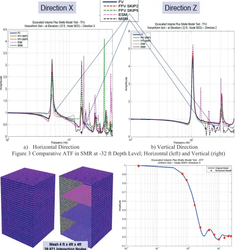
Figure 3 illustrates the accuracy performance of the five SSI modelling scenarios. Selected results show the acceleration transfer function (ATF) amplitudes in horizontal and vertical directions on the SMR foundation at the -32ft depth that is ¼ of the total embedment depth. It should be noted that except
FFV-Skip2, all the other excavation “reduced-order models” provide results that deviate from the “reference”
FV method. ESM performs the worst, even poorer than MSM. For the SMR problem at hand, only the FFV-Skip2 results match very closely the FV results for the entire frequency range. The conclusion is valid for any node locations within the SMR foundation. Based on the obtained results, we recommend the use of the FFV-Skip2 for typical SMR problems. The SSI analysis runtime savings are about 80% for FFV-Skip2 in comparison with FV as described in Figure 3.
Excavation Horizontal Mesh Size
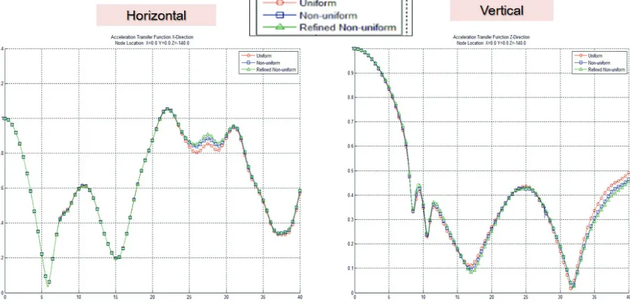
excavation horizontal mesh size is 1.5-2.0 times larger than the vertical mesh size, or even larger, the computed SSI responses are still reasonably accurate. Herein, a comparison of SSI results for two different horizontal embedment mesh sizes is presented. The two SMR embedment horizontal meshes are i) 8ft mesh size inclusing 7,938 interaction nodes, shown in Figure 1, and ii) 4ft mesh size including 29,371 interaction nodes, as shown in Figure 4 (left). The soil profile was assumed to be uniform with a Vs = 1,000 fps. Seismic input motion was defined at the ground surface. The comparative computed ATF results in Figure 4 (right) show that the use of a horizontal mesh size of 4ft instead of 8ft, although increases by about 10 times the SSI analysis runtime and by about 4 times the number of interaction nodes and the memory storage, has a negligible impact on the SSI response accuracy. We recommend to SSI analysts to always perform preliminary sensitivity analysis with different excavation horizontal mesh sizes rather than use directly a small mesh size that is equal to the vertical mesh size. The saving for the SSI analysis runtime could be tremendous.
Excavation Mesh Nonuniformity
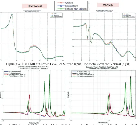
Figure 5 (left) shows the SMR SSI model considered for the study. The SMR structure has a size of 200ft x 100ft x 100ft (H x L x W) and an embedment of 140ft depth. The soil profile shown in Figure 5 (right) was assumed to be highly non-uniform with a soil stiffness inversion within the SMR embedment depth. Three embedment mesh scenarios were assumed as illustrated in Figure 6: i) Uniform mesh size, ii) Non-uniform mesh size, and iii) Refined non-Non-uniform mesh size.
Figures 7 and 8 show the ATF amplitudes computed for the three mesh scenarios in the horizontal and vertical directions within the SMR model at the foundation level and the ground surface level. The computed SSI responses indicate a close agreement between the three excavation mesh models. Based on the obtained results, the effects of the excavation horizontal mesh nonuniformity on the SSI responses appears less significant.
Excavation Cavity vs. Foundation Models
The SMR massless foundation model and the two layer soil profile shown in Figures 1 and 2 are used. Both the FV and the FFV-Skip2 methods are applied. The SSI analysis is performed for the SMR massless foundation model (EM) and for its excavation cavity model (ECM) that includes only the excavation volume elements and no structure or foundation elements. The ECM model includes only the excavated soil cavity.
Figure 9 shows the SMR foundation model results in terms of the ATF computed in the horizontal and vertical directions at the SMR foundation level for the input motion defined at the outcrop level (top of soil layer 13) and the foundation level (top of soil layer 31), respectively.
Figure 10 shows the ECM model results in terms of the ATF computed in horizontal and vertical directions at the SMR foundation level for the input motion defined at the outcrop level (top of soil layer 13). It should be noted that the ATF results in Figure 9 obtained for the SMR FM model indicate that the FV and FFV-Skip2 methods provide basically identical results for both seismic input level scenarios at the outcrop and foundation levels. However, it should be noted that the ATF results in Figure 10 obtained for the SMR ECM model show a much poorer matching between the two methods, also indicating that both FV and FFV-Skip2 are numerically less stable. The ATF curves for ECM are less smooth.
instead of ECM. If ECM is used, then, the conclusions based on result comparisons could be affected by the poor numerical condition of the excavation model in soft soils. We recommend the use of realistic SMR foundation massless models for such validation studies rather than ECM that could be numerically overly sensitive.
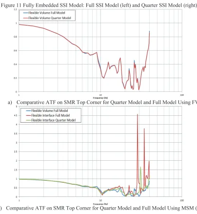
Quarter SSI Models vs. Full SSI Models
As known, Quarter SSI models provide identical results with Full SSI models for the double symmetric SSI models. However, is not fully true. When the embedded SSI model is numerically sensitive, Quarter SSI models may provide results which are slightly different than Full SSI models. It appears that the symmetric and antisymmetric kinematic boundary conditions imposed to the Quarter SSI models help the numerical stability of sensitive FE models, and, therefore, for such sensitive FE models they behave more stable than the Full SSI models. Figure 11 shows for a fully embedded structure the Full SSI model (left) and the Quarter SSI model (right). Figure 12a shows a comparison for the ATF computed at the top corner of the embedded foundation for the Quarter and Full SSI models using the “reference” FV method. As expected, the ATF results overlap.
In contrast, Figure 12b shows a comparison for the ATF computed at the top corner of the embedded SMR foundation for the Quarter and Full SSI models using the MSM method (with the interaction nodes defined on the outer surface of the excavation volume). The ATF results are different for Quarter and Full SSI models. As shown in Figure 12b, the Quarter SSI model with MSM is more stable than the Full SSI model with MSM. These ATF results raised the question on how reliable are the MSM Quarter SSI model results for checking the numerical accuracy of the MSM Full SSI models. Based on these results, the use of Quarter SSI models to validate the Full SSI model accuracy might be not always appropriate for MSM, since as shown herein, the MSM Full model could be significantly more unstable than the MSM Quarter model. Thus, the conclusions drawn from the Quarter SSI models related to the applied SSI subtructuring method accuracy could be different than the conclusions drawn directly from the Full SSI models.
REFERENCES
Ghiocel, D.M. (2011). “Flexible Volume (FV or DM), Flexible Interface Foundation-Soil-Interface-Nodes FSIN or Subtraction and Excavation-Volume-Boundary-Foundation-Soil-Interface-Nodes EVBN or Modified Subtraction Methods: A Series of Case Studies”, presented to the Defense Nuclear Facility Safety Board (DNFSB), Washington D.C, March, 30
Ghiocel, D.M., Yue, D., Fuyama, H., Kitani, T. and McKenna, M.(2013).”Validation of Modified Subtraction Method for Seismic SSI Analysis of Large-Size Embedded Nuclear Islands”, SMiRT22 Proceedings, Division V, San Francisco, California, August 18-23
Ghiocel D, M. (2014). SASSI Methodology-Based Sensitivity Studies for Deeply Embedded Structures Such As Small Modular Reactors (SMRs)”, U.S. Department of Energy Natural Phenomena Hazards Meeting, Session on "Soil-Structure Interaction", Germantown, MD, USA, October 21-22
http://www.energy.gov/sites/prod/files/2015/05/f22/DOE-NH-SMR-SSI-Methods-Oct-21-2014.pdf.
Ghiocel Predictive Technologies, Inc. (2015). “ACS SASSI - An Advanced Computational Software for 3D Dynamic Analyses Including SSI Effects”, ACS SASSI Version 3.0 Manuals, March 31,
http://www.ghiocel-tech.com/enggTools/ACS%20SASSI_V300_Brief_Description_Dec_31_2014.pdf
Figure 1 SMR Massless SSI Model; Outside View (left) and Vertical Section (right)
a) Horizontal Direction b) Vertical Direction
Figure 3 Comparative ATF in SMR at -32 ft Depth Level; Horizontal (left) and Vertical (right)
a) Refined Mesh SMR model b) Comparative ATF in Horizontal Direction
Figure 5 SMR SSI Model for Excavation Mesh Study (left) with Nonuniform Soil Profile (right)
Figure 6 SMR Excavated Soil Mesh Models: i) Uniform, ii) Non-uniform and iii) Refined Non-Uniform
Figure 8 ATF in SMR at Surface Level for Surface Input; Horizontal (left) and Vertical (right)
Figure 9 ATF for the SMR Foundation Model (FM) Computed at Foundation Level for Nonuniform Soil with Outcrop and Foundation Inputs (Top of Layer 13 and Top of Layer 31)
Figure 11 Fully Embedded SSI Model: Full SSI Model (left) and Quarter SSI Model (right)
a) Comparative ATF on SMR Top Corner for Quarter Model and Full Model Using FV
b) Comparative ATF on SMR Top Corner for Quarter Model and Full Model Using MSM (or FI)