Substructuring As A Tool For Design Of Floor Slabs
K.V.Subramanian 1), M.S.Bavare 1), H.A.Mapari 1), U.S.P.Verma 2), A.Shrivastava 2) and N.M.Rao 2) 1) TCE Consulting Engineers Limited, Mumbai, India
2) Nuclear Power Corporation of India Limited, Mumbai, India A B S T R A C T
In most of the complex Finite Element (FE) Modelling analyses sub-components if included in the global model of structure may cause extremely large problem size. This would not render themselves to a cost-effective analysis solutions. This is due to modelling efforts, post-analysis processing efforts & time factor involved. A rational yet cost- effective approach is to go for an application of concept of sub-structuring for design of local regions e.g. floor slabs as presented in this paper. The extent of the sub-structure could be limited adequately beyond the region of interest.
I N T R O D U C T I O N
Internal Structures (IS) of Reactor Buildings of Nuclear Power plants are complex Reinforced Concrete (RC) structures in terms of structural analysis, design & construction. Structural analysis is carried out on a Global Finite element model. In the global model representation of floor in its finer form to model local areas, cut-outs etc is not necessary, since focus is on the design of walls. As far as the design of floors is concerned, element results for some floor regions in the global model can not be used because coarse meshing has represented the floor. Due to large size of mathematical problem, the concept of sub-structuring is employed which is rational.
This paper illustrates the application of sub-structuring in the complex environment to analyse & design of floor slabs.
S T R U C T U R A L A R R A N G E M E N T
The IS of Reactor building comprises of RC floors, RC walls, RC & structural steel columns. A typical floor considered in the paper is a reinforced concrete floor. General slab thickness about 1000 mm. Floor is constructed with concrete mix with heavy density aggregate as a radiation-shielding requirement. The floor slab is constructed integrally with RC wall beam-arrangement. The floor has circular periphery around; the floor has cut-outs as operational requirement of the plant. The whole structure is supported on a common mat foundation.
NEED OF S U B - S T R U C T U R I N G AND M O D E L A D O P T E D
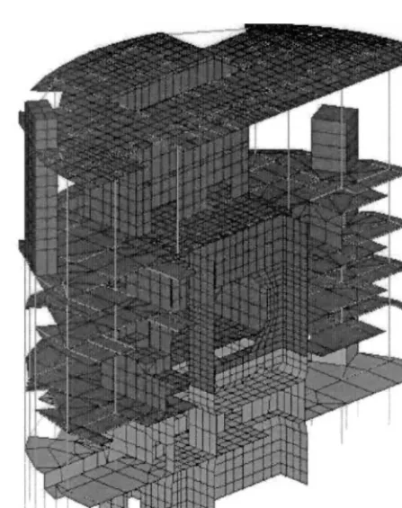
Being a part of a complex three-dimensional Internal Structure (IS) consisting primarily of RC walls, RC floor slabs, and columns of RC & steel; modelling of the structure is an appreciably complex job. (Refer Fig. 1). The structural geometry is symmetric about the East-West centre-line. As such North half of the structure is modelled & analysed with appropriate boundary conditions on EW symmetry plane depending upon the loading layout either symmetric or ant- symmetric. A general refinement of the global model would end up into an un-manageable analytical model in terms of computer memory, time etc. Further it is computationally intensive work due to a variety of loading types, load combinations, scrutiny for critical combinations & finally the element-wise reinforcement design. As far as design of floors is concerned, it was contemplated that element results of global model would not provide reasonably accurate information like membrane forces, bending moments, and out of plane & in plane shear forces for design of floors.
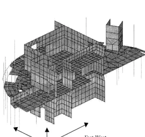
As such it was considered to adopt sub,structuring approach for the floor. In the domain of sub-structure; along with the floor of interest, its connecting walls above & below are included up to next floor levels above & below but excluding those floors (Refer Fig.2). The element regions of the floor are subdivided, forming a finer mesh. For enhanced accuracy, isoparametric 8-node shell element is used for discretising the sub-structure. This element provides benefit of calculations of transverse shear forces as well as it accounts for shear deflections. Sets of displacement boundary conditions are specified at nodes common between sub-structure & global model depending upon the nature of the load as described in next paragraph.
SMiRT 16, Washington DC, August 2001 Paper # 1676
Types Of Loading
The structural analyses for global model & sub-structure are carried out for loading like self weight of structure, floor live loads during normal operating conditions as well as during erection & shut-down conditions, hydrostatic loading, equipment loads (Ro), operating temperature (To), accident pressure (Pa), accident temperature (Ta), seismic loading like SSE & OBE along NS, EW &Vertical directions.
Global Model
Structural analysis of the global three-dimensional model of Intemal Structure is carried out wherein the floor slabs, walls, columns are included in the model (Refer Fig.l). The quadrilateral shell element & three-dimensional elastic beam element used are used for the design of walls & columns of the structure. The floor slabs are modelled coarsely to represent essentially their in-plane rigidity. For this reason, these results obtained for floor slabs can not be used for design of floors.
Procedure adopted, for global analysis is outlined as under;
• Structure as a whole being symmetric, half structure is discretised, with nodes on symmetry plane appropriately restrained depending upon symmetry or anti-symmetry of loads.
• Nodes at junction with mat foundation are fixed in all six Degrees Of Freedom (DOF).
• FE analysis of the entire structural system (global model) is carried out for the load cases individually.
• Displacement results of global model after analysis are extracted for the nodes defining the boundaries (to be applied on the substructure defined below). These displacements would serve as boundary displacements for sub-structure described below.
~i i! i
S u b - S t r u c t u r e
Analysis of sub-structure is performed as below following the global analysis as discussed earlier.
1. A portion of the global structure (i.e. a substructure) comprising of the floor slab of interest with walls & columns joining the floor to the next floor level above & below is cut from the global model. The floor slabs are generally of large thickness; as such higher order shell element (eight-node isoparametric type) including effect of shear deflections is used, for enhanced accuracy. Model of the floor developed thus is further refined enabling the modelling of all openings, cut-outs etc & precise locations for application of floor loading.
2. For load cases like gravity loads, distributed live loads etc, fixed boundary conditions are specified at the nodes along cut-boundaries. It was considered that application of displacements loading (on boundaries of sub- structure) using global model displacement results is unnecessary, since a major lateral sway was not observed under these loading.
3. In the cases of loads causing side sway like seismic loading Safe Shut-down Earthquake (SSE) along EW & NS directions, displacement components (translational Ux, Uy, Uz & rotational ROTx, ROTy, ROTz) at the boundary between sub-structure & global structure need to be specified at the substructure boundaries. Except in case of vertical seismic loading appropriate representation (as stated in 2 above) is made to depict the flexural bending of the floor slab.
4. The loads (e.g. nodal loading, elemental surface pressures, gravity loading, body forces like temperatures etc) used on the global model but now within the domain of sub-structure are applied on the sub-structure.
5. With the above, FE analysis of the sub-structure is carried out for elemental forces. Combinations of element forces are performed (as per ACI: 349-1985). Seismic combinations between North-South (NS), East-West (EW) & Vertical components are carried out as per 100-40-40-combination rule. Seismic combination effects are combined with non-seismic loading as per ACI: 349-1985. Design of RC section is carried out as per ACI: 349-1985.
ii ii :ii .~. !ii~...~i . . . ,.~i:!~ ~ ... ~;',~,', ~iil .Nii N *~:~~ ~J N ~-~'~ ... '!: !!~ ~ii
i .... !
, . . .
i i i • ....
i
~ ~ ~ t-West
Nbrth-South
RESULTS
A comparison of element forces in the floor slab is presented in Graphs 1 through 4 for demonstrating the efficacy of sub-structuring approach.
8O
E 40 •
~o liiiiii!:ii~
i i
i ii!iiiii i i
i i i
~
i I
li iiii
~
i ii i iiii i ii iiiii
i i~i
i i I
= 7 iiii ~li~i~ iiiii~ii~iiiiiiiiiii}iiiiiiiiii}iiiiiiiiiiiiiiiiiiiiii i iiiii iiii~o liiiiiiiiiiiiiiiii i i i( iiiiii
X - C O O R D ( m )
Graph :1 Bending moment (Mx) plot along EW direction for Dead load case
-
.~ool
i i
i
ii
i i liiiil iii ii ii ii iii ii I
~oo ~iiiiii i?iiiiiiiiiiiWiiiiiiiiii~iiii
iiiiiii
ii i i iiiii iiii iiiiiilBiiiiiiii?iiiii~
i!!!!! !!i!! ~!!!!i!! !!!!!!iiii!
,?
~ooo ~
! !!! !!!!
iiiii ii i iiiiiiiiiiiiiiiiiiiii
iiiiiiii iiiiiiiiiiiii?iiiiiiiiiii
iiii iiiiiiiiiii i
X-C OORD ( m )
Graph :2 Membrane force (Tx) variation along a strip in EW direction for Ta case.
~oo ~
-
o ~
! ! ! i !
I
i
~
!!!!!!!!!
iii
iii iiiiiiiiiiiiiiiiiiiiiiiiiiiiiii
iiiiii!iii!iii!!!l!iiiiiii
iiiiiii iiii i iii iiiiiiiiiiiiiii!!!iiiiiiiiii iiiii
iiiiiiiiiii
iiiiiiiiiiiiiii
iiiii iiiiI
X-C OORD ( m )
o.6
!i
~ [ ~ ~ i i ~ i i i
i i
i
, 5 ...
_ o.4 Ii
0.3i
!
i iiiiiiiiiiiiiiiiiiiiiiiiiiiiiill
,ii
i i
ii
0.2 i
i
~
i ii i i i i i
i iiii i il
i iiiiiiiiiiii i liili
i i i i
]
i
i i
iiiiii i iiiiiiiiii iii i ii i
i ii
o
I
ii i i
~ i l
i
iiiiiiii
ii
!ii
I
-°l~ii
i i
~ii~',ii~ i
iiiiii!i:.iii~ii~iii~ i i ii i~iiii i!ii
iii iii i ii~iif,
i
~
r~
-0.2-0.a
!!
i
i i i
!
i N
i iil
-04 J
~
~
X-COORDINATE (M)
Graph
"4 Vertical Displacements (Uz) for SSE-EW Case OBSERVATIONS & DISCUSSION OF RESULTSGraphs on the variation of element forces along an element strip in EW direction of structures are presented. Following are the observations.
From Graph:-1: Global modelling of the floor slab shows lesser moments in the floor slab in relation to sub- model especially near the junction with walls at the end of the floor panel.
From Graph:-2 : Global modelling of the floor slab shows lesser membrane force in the floor slab in relation to sub-model.
From Graph:-3 : Global modelling of the floor slab shows close matching of moment diagram for SSE:EW case which is a sway case.
From Graph:-4 : Global modelling of the floor slab shows close matching of Vertical displacements Uz in the floor slab in relation to sub-model.
It appears from the graphs that, the sub-model results are higher than those of the global model, as such it shall be used for the RCC design of floor slab.
C O N C L U S I O N
Concept of sub-structuring as applied in the analysis of floor slab systems in Reactor Building is described in this paper. The approach involves less computational time, effort, saving in resources & in data processing. Such an approach is highly recommended in similar situations.
A C K N O W L E D G E M E N T
The authors thank the management of TCE Consulting Engineers Limited and Nuclear Power Corporation of India Limited for the constant encouragement received and having given the permission to publish this paper.
N O M E N C L A T U R E
ACI American Concrete Institute
DOF = Degree Of Freedom
EW = East West
IS = Internal Structure
NS = North South
OBE Operating Basis Earthquake
Pa = Accident pressure
RCC or RC ROTx, ROTy, ROTz
SSE To, Ta Ux, Uy, Uz
respectively.
Reinforced Cement Concrete
Nodal Rotational displacement components about global, X,Y, and Z-direction of structure.
Safe Shut down Earihquake
Temperature loading during normal operating & accident conditions respectively. Nodal Translational displacements, respectively along global X,Y, and Z-directions of structure.
R E F E R E N C E S