Division V
SENSITIVITY OF EMBEDDED STRUCTURES TO FLOOR DIAPHRAGM
ACTION IN SEISMIC SSI ANALYSIS
Ayman Saudy1 and Medhat Elgohary2
1 Senior Technical Expert, Civil & Seismic Engineering, Amec Foster Wheeler, Canada 2 Manager, Civil & Seismic Engineering, Amec Foster Wheeler, Canada
INTRODUCTION
To determine their seismic responses, safety-related structures are numerically simulated by either a lumped-mass-stick (LMS) model or a 3D shell; i.e. consistent-mass, (3DS) model, per standards such as CSA N289.3 and ASCE 4-16. LMS models are required to capture and understand the overall structural behaviour, while 3DS models provide more detailed and accurate local responses and can be used for design purposes. The validation of analysis models in adequately capturing the global dynamic characteristics as well as the localized structural responses of the real structure is mandated by applicable nuclear codes and standards. In addition, in lieu of inspecting sensitivity of the analysis model to key modelling parameters, LMS models can generally be used to validate more detailed 3DS models.
The development of LMS models for embedded shear wall structures needs to account for the stiffness of different structural elements; particularly its basement walls and base slab. In addition to the structural embedment effect and how it is simulated, the effect of floor diaphragm action is a potential contributor to the responses of the structure. Sensitivity of the structural seismic responses to element type, configuration, and material mechanical properties used in simulating the in-plane diaphragm action of floors below grade should be investigated.
This paper presents a summary of investigations carried out to identify sources for the differences in the seismic responses determined using a LMS model and a 3DS model of a typical embedded safety-related shear wall structure. Based on the identified sources, a set of recommendations for strategies to model the structure using LMS models for use in seismic SSI analyses is made.
MODELLING APPROACHES
Two modelling approaches are generally followed in simulating geometry and both mass and stiffness properties of safety-related structures to determine their responses to seismic loads. These are the Lumped-Mass-Stick (LMS) and 3D Shell (3DS); i.e. consistent-mass, modelling approaches. Both modelling approaches are quite suitable and generally followed in the seismic analyses for structural responses including Soil-Structure-Interaction (SSI) effects.
The following steps are followed when the LMS modelling approach is used to simulate the dynamic characteristics of the super-structure:
• Each floor is considered to rigidly connect the lateral-load resisting mechanisms in its own plane. • Stiffness properties (axial, flexural & shear) of the lateral-load resisting mechanisms are represented
by massless beam elements connecting between rigid floors and located at respective shear centres. • Mass of the structure is lumped at a sufficient number of nodes located at elevations of rigid floors. • Equivalent mass for live loads on and equipment anchored to floors is included in the lumped masses. • Eccentricities of floor masses are accounted for by offsetting the lumped masses to a set of mass
When a 3DS modelling approach is used to simulate the dynamic characteristics of the super-structure, then, the following steps are followed:
• Geometry of different load-carrying structural parts; e.g. columns, beams, floor slabs, is represented by beam, shell or solid elements.
• Sectional properties are assigned to the elements to model structural stiffness (axial, flexural &shear). • Mass of the structure is accounted for via assigned material densities to beam, shell or solid elements. • Live loads on floors and platform live loads are included as added equivalent floor densities and mass
of equipment is assigned to nodes at their respective locations.
• Floor eccentricities are implicitly accounted for via the spatial geometrical modelling of all stiffness elements and the precise distribution of structural and equipment masses.
In case of surface foundation, solid elements are generally used in modelling the basemat transferring the structural loads to the supporting soil. However, in case of embedded structures, basement walls below grade need to be modelled with either shell or solid elements to be able to adequately simulate both the interaction with retained soils and the potential separation between the basement walls and foundation from the supporting soils.
When a sub-structuring technique, as the one proposed by Lysmer, is used to perform seismic SSI analyses of embedded structures, two more models are needed in addition to the model of the structure: a model for soil layering and another for soil excavations. The soil model describes the horizontally layered soil around and beneath the embedded structure overlaying an elastic half-space. The soil excavation model represents the soil volume that is removed for the below-grade part of the structure. Adequately-sized soil layers and solid elements for soil excavation volume to enable effective seismic wave propagation within the frequency range of interest, per CSA N289.3 and ASCE 4-16.
A CASE STUDY
A typical safety-related structure is required to perform assigned safety functions during different plant conditions. These safety functions include housing and protection of safety-related mechanical, electrical and control components from the harmful effects of common mode failures such as seismic events.
In this study, a six-storey reinforced concrete structure is investigated. The layout of the structure is characterized with internal and external reinforced concrete shear walls extending along its height. While the external walls have very limited openings, the internal walls are laid out to form, along with the floor slabs, compartments or rooms for different uses. The overall footprint of the structure is approximately 52m long by 40m wide and its total height is about 46m. The structure is partially embedded about 20m below grade. The basemat is a 2.5 m thick raft foundation directly bearing on the supporting soil.
Two models were developed for the structure: a LMS model and a 3DS model. The LMS model is used for determining the overall dynamic characteristics of the structure and the structural seismic responses at key locations. The 3DS model is used in the detailed design of the structure per applicable design codes. The two models were developed ensuring their corresponding dynamic characteristics match each other such that sources of potential discrepancies of their responses are eliminated.
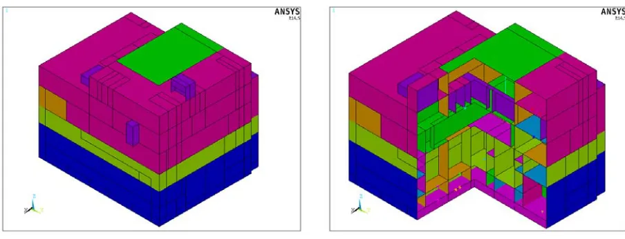
3DS Model
elements. Force transfer (moment and shear) between beam elements, shell elements, and solid elements is adequately simulated. Figure 1 presents the 3DS model of the studied structure.
Figure 1. Consistent-Mass-Stiffness (3DS) Model
LMS Model
The LMS model of the structure includes (a) the basemat and portions of below-grade external walls, and (b) a lumped-mass stick for the rest of the structure. In addition to all floor slabs, the lumped-mass stick represents below-grade internal walls and above-grade internal and external walls of the structure.
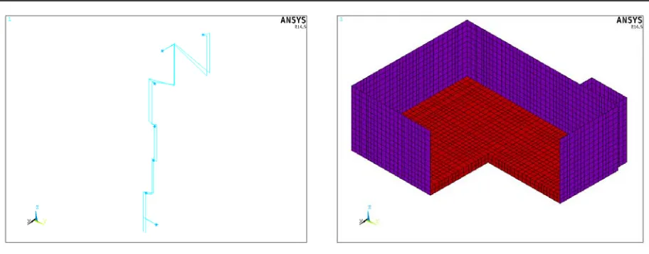
The stick part of the model is made of two sets of vertical beam elements, or sticks representing the structure’s flexural and axial stiffness. The wall system between any two floors is modelled using two beam elements placed vertically at the wall system’s centres of flexural and axial stiffness. Because the centres of flexural and axial stiffness are not aligned vertically, the beam elements at each floor characterizing the top and bottom wall systems are connected with rigid links. In addition, floor masses are lumped at nodes corresponding to the centre of mass for each floor. A set of oscillators are introduced at the locations of lumped floor masses to simulate vertical vibrations of floor slabs. The lumped masses are connected to the corresponding stick beams using rigid links. The basemat and external walls below grade are explicitly modelled. Due to its relatively large thickness, solid elements are used to model the basemat. Below-grade external walls are modelled using shell elements. Force transfer (moment and shear) between shells of the external walls and solids of the basemat is adequately simulated. Figure 2 presents the stick part and exterior walls and basement part of the LMS model.
(a) Stick Part (b) Exterior Walls & Basemat Part Figure 2. Stick & Basemat Parts of Lumped-Mas-Stick (LMS) Model
Figure 3. Lumped-Mas-Stick (LMS) Model
SENSITIVITY OF RIGID LINKS
Modal analysis of each of the two models was carried out. Surface foundation were assumed in these analyses, i.e. only the nodes of the basemat bottom surface are restrained. The analysis for each model includes the effect of shear deformations developed in beam elements simulating flexural response. The dynamic characteristics of the structures as determined based on each of the two models are listed in Table 1. The LMS model is found to be stiffer than the 3DS model since its fundamental frequency is different from that of the 3DS model by 24%. Since the total mass for each of the two models is identical, the stiffer response of the LMS model is attributed to how the diaphragm action; i.e. in-plane stiffness, of below-grade floors is simulated. This section presents studies performed to investigate the effect of how diaphragm action of below-grade floors is simulated on the structural seismic responses.
Table 1: Dynamic Characteristics of LMS & 3DS Models
Model f1x (Hz) f1y (Hz) f1z (Hz)
3DS 6.90 (EFR = 84.7%) 6.49 (EFR = 84.5%) 18.59 (EFR = 82.4%)
LMS 8.55 (EFR = 63.8%) 9.78 (EFR = 54.0%) 14.37 (EFR = 81.7%)
Sensitivity to Rigidity of Beams
To investigate the sensitivity of the LMS model to the rigidity assigned to the rigid beams forming the diaphragm action of below-grade floor slabs, the rigidity of the beam elements are varied. Modal analyses were carried out for different models with different rigidities assigned to the beam elements. In addition to restraining all nodes of the bottom surface of the basemat, out-of-plane degrees of freedom of all nodes of below-grade external walls are restrained. The premise is that if the LMS model is found to be sensitive to the rigidity of the rigid links, one can conclude that an optimized rigidity to be assigned to the beam elements of the rigid links would need to be evaluated since the LMS response would be sensitive to this is parameter.
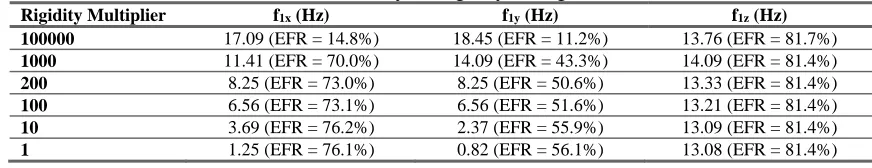
Table 2 presents the dynamic characteristics of this LMS model when the rigidity of the rigid beams is modified by a multiplier. The rigidity multiplier ranges from 1 to 100000. The three fundamental frequencies in each of the three global directions are tabulated along with their effective mass ratios. The fundamental frequencies in the lateral directions are confirmed to be sensitive to the rigidity assigned to the rigid beams. In addition, the effective mass contributions to the lateral vibration increase to more than 50% instead of about 11% for the case used in the analysis response comparison study. This finding is consistent with the observed stiffer behaviour of the surface-foundation LMS model as presented in in Table 1.
Table 2: Sensitivity to Rigidity of Rigid Beams
Rigidity Multiplier f1x (Hz) f1y (Hz) f1z (Hz)
100000 17.09 (EFR = 14.8%) 18.45 (EFR = 11.2%) 13.76 (EFR = 81.7%)
1000 11.41 (EFR = 70.0%) 14.09 (EFR = 43.3%) 14.09 (EFR = 81.4%)
200 8.25 (EFR = 73.0%) 8.25 (EFR = 50.6%) 13.33 (EFR = 81.4%)
100 6.56 (EFR = 73.1%) 6.56 (EFR = 51.6%) 13.21 (EFR = 81.4%)
10 3.69 (EFR = 76.2%) 2.37 (EFR = 55.9%) 13.09 (EFR = 81.4%)
1 1.25 (EFR = 76.1%) 0.82 (EFR = 56.1%) 13.08 (EFR = 81.4%)
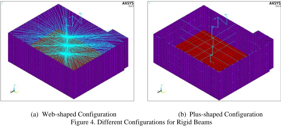
Sensitivity to Configuration of Links
To investigate the sensitivity of the LMS model to the configuration of rigid beams forming the diaphragm action of the basement floors, two alternate configurations were used in addition to the ‘X-shaped’ beams connecting each below-grade floor mass to the corner nodes of the external walls at the floor level. In the first alternate configuration, the diaphragm action is simulated via rigid beams connecting the floor centre of mass to all the nodes of below-grade external walls at the floor level forming a ‘Web-shaped’ configuration. No rigid beams is defined within the plane of the exterior walls at each floor level in this configuration. In the second alternate configuration, the set of rigid beams of the X-shaped configuration are replaced with a set of four beams connecting the basement floor mass to the mid nodes of the four below-grade external walls. The rigid beams defined within the plane of the external walls are kept in this ‘shaped’ configuration. Figure 4 presents the web-shaped and plus-shaped configurations of rigid beams. Table 3 presents the dynamic characteristics of the fixed-base LMS model for the three different configurations used in simulating diaphragm action of basement floors. The rigidity multiplier of the rigid beams used in the three configuration is 100000. The three fundamental frequencies in each of the three global directions are tabulated along with their effective mass ratios.
Table 3: Sensitivity to Configuration of Rigid Links
Configuration f1x (Hz) f1y (Hz) f1z (Hz)
X shaped 17.09 (EFR = 14.8%) 18.45 (EFR = 11.2%) 13.76 (EFR = 81.7%)
Web shaped 14.83 (EFR = 14.5%) 19.17 (EFR = 11.0%) 14.02 (EFR = 82.0%)
In another study, the effect of adding a diaphragm at the top surface of basemat is investigated. Modal analyses were carried out for different models with different configurations of rigid links simulating diaphragm action. The premise is that if the LMS model is found to be sensitive to the configuration of rigid links or to adding another diaphragm at the top of basemat level, one can conclude that a more refined configuration for the diaphragm action would be recommended for the LMS modelling. Table 4 presents the dynamic characteristics of the LMS model when diaphragm action is considered at the top surface of the basemat in each of the three configuration.
(a) Web-shaped Configuration (b) Plus-shaped Configuration Figure 4. Different Configurations for Rigid Beams
Table 4: Sensitivity to Additional Rigid Links at Basemat Level
Configuration f1x (Hz) f1y (Hz) f1z (Hz)
X shaped 17.09 (EFR = 14.8%) 18.46 (EFR = 11.2%) 13.77 (EFR = 81.7%)
Web shaped 14.83 (EFR = 14.5%) 19.19 (EFR = 11.1%) 14.03 (EFR = 81.8%)
Plus shaped 16.99 (EFR = 14.7%) 18.34 (EFR = 11.3%) 13.72 (EFR = 81.7%)
The fundamental frequencies of the LMS model are found to be sensitive to the configuration of rigid links simulating diaphragm action of basement floors. Therefore, it can be concluded that the configuration of rigid beams simulating diaphragm action of the below-grade floors can impact the dynamic characteristics of the LMS model.
In addition, adding a diaphragm action connecting the floor mass at the top of the basemat to the external below-grade walls in any of the three configuration has no effect on the dynamic characteristics of the LMS model. Therefore, it can be concluded that there is no need for additional simulation of the connection between the stick and external below-grade walls at the basemat level.
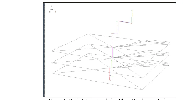
Figure 5. Rigid Links simulating Floor Diaphragm Action
STRUCTURAL SEISMIC SSI ANALYSIS
Standard design parameters describing geotechnical conditions and seismicity of the site were defined for the seismic analyses of the LMS and 3DS models accounting for SSI effects. A uniform geotechnical site condition is defined for this study as the Best Estimate (BE) soil properties of the hard site category according to Volume 2 of the European Utility Requirements (EUR). With regard to site seismicity, the design basis earthquake (DBE) for the structure is defined as EUR’s design ground response spectrum for hard sites. A set of three spectrum-compatible time histories were used in the seismic SSI analysis of the two models.
The SSI analyses were carried out using ACS-SASSI program following the sub-structuring technique [8] where flexible interface method is used to simulate the interaction effects of the soil with foundation. The control motion is defined at the grade level; i.e. surface. The cut-off for range of frequencies of the propagating ground motion waves is set at 50 Hz.
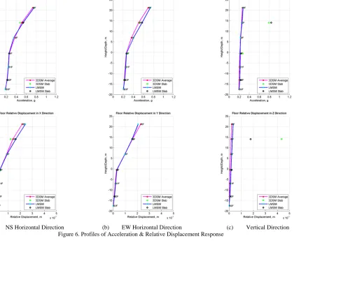
The floor acceleration and relative displacement responses along the height are generally consistent with the expected structural behaviour – i.e. higher response takes place at higher elevations. This trend is valid below grade as well as above grade; however, due to embedment, the trend below grade is less than above grade. Figure 6 presents the comparison of the profiles of acceleration and relative displacement responses for the two models. The figure shows the average floor response in case of the 3DS model. It can be observed that the maximum floor acceleration and relative displacement responses in the horizontal and vertical directions from the LMS model generally match the corresponding responses from the 3DS model.
(a) NS Horizontal Direction (b) EW Horizontal Direction
(c) Vertical Direction
SUMMARY & CONCLUSIONS
The development of lumped-mass-stick models for embedded shear wall structures need to account for relative stiffness of different structural elements; particularly its below-grade walls and basemat. Therefore, the effect of floor diaphragm action is a potential contributor to the responses of the structure. Sensitivity of the structural seismic responses to how in-plane diaphragm action of floors below grade is simulated is investigated.
Two analysis models of a typical safety related embedded structure: a lumped-mass-stick model and a consistent-mass-stiffness model, were developed for the purpose of investigating the floor diaphragm action effect on the structural seismic responses. The lumped-mass-stick model of the embedded structure consists of two parts: (a) a stick formed of beam elements and (b) a shell-and-solid element part for below-grade external wall and basemat. A set of rigid beams is used to simulate the diaphragm action of each below grade floor connecting the stick part of the model to the external walls.
Sensitivity of the lumped-mass-stick model to the configuration and rigidity of the set of rigid beams forming the floor diaphragm action is investigated. Based on the results of the performed investigations to evaluate the effect of how diaphragm action of below-grade floors is simulated, the following conclusions can be made.
• Level of rigidity assigned to elements simulating the diaphragm action of below-grade floors has a significant effect on the LMS model’s dynamic characteristics and in turn on its structural response to seismic motion.
• Configuration of rigid beams simulating the diaphragm action of below-grade floors has no effect on the dynamic characteristics of the LMS model.
• No need to include additional simulation of the diaphragm action at the basemat level.
The lumped-mass-stick model was updated based on the findings from the sensitivity studies. Then, seismic SSI analyses of each of the two models were carried out to determine their structural responses. Profiles of acceleration and relative displacement responses along the height and in-structure floor response spectra at key floor locations were evaluated and compared. Based on the response comparison, it can be observed that responses of the optimized lumped-mass-stick model generally match the corresponding responses of the consistent-mass-stiffness model.
It is recommended to validate the structural responses of the lumped-mass-stick model used in the analysis of embedded shear wall structures since the seismic responses are found to be sensitive to how floor diaphragm action is simulated
REFERENCES
American Society of Civil Engineers Standard ASCE/SEI 4-16. (2017). Seismic Analysis of Safety-Related Nuclear Structures. Reston, Virginia, USA.
Canadian Standard Association (CSA) Standard N289.3-10. (2010). Design Procedures for Seismic Qualification of Nuclear Power Plants. Mississauga, Ontario, Canada.
John Lysmer. (1978). "Analytical Procedures in Soil Dynamics," Report No. UCB/EERC-78-29, Earthquake Engineering Research Center, University of California, Berkeley, California, USA.
European Utility Requirements for LWR Nuclear Power Plants. (2012). Volume 2. Generic Nuclear Island Requirements.