Volume 2010, Article ID 420767,11pages doi:10.1155/2010/420767
Research Article
TOA Estimation and Data Association for Through-Wall
Tracking of Moving Targets
Jana Rov ˇn´akov´a and Duˇsan Kocur
Department of Electronics and Multimedia Communications, Technical University of Koˇsice, Faculty of Electrical Engineering and Informatics, Letn´a 9, 041 20 Koˇsice, Slovakia
Correspondence should be addressed to Jana Rov ˇn´akov´a,[email protected]
Received 2 December 2009; Revised 2 July 2010; Accepted 6 August 2010
Academic Editor: Sherwood W. Samn
Copyright © 2010 J. Rov ˇn´akov´a and D. Kocur. This is an open access article distributed under the Creative Commons Attribution License, which permits unrestricted use, distribution, and reproduction in any medium, provided the original work is properly cited.
Through-wall tracking of moving targets is of great interest for rescue, surveillance, and security operations. For its realization, the handheld ultrawideband radars with small antenna array provide a practical solution. The radar signal processing, which is hidden behind the estimation of the final target tracks, represents a complex process with several processing phases. In this paper, all phases for through wall tracking are outlined whereas the attention is devoted to the estimation of the correct input data for the localization phase. This is done by applying a new approach that combines the time of arrival (TOA) estimation and the data-association into a single step. The properties of the proposed algorithm are illustrated by processing of real radar signals. Here, the obtained results confirm that the proposed algorithm has provided good, stable, and robust TOA estimation including deghosting task solution.
1. Introduction
Through wall tracking of moving targets is very helpful in the situations where the entering of a room or a building is considered hazardous and it is desired to inspect its interior from outside through the walls. Examples include tracking of people in the dangerous environments (for purposes of policemen, firemen), through rubble localization following an emergency (e.g., earthquake, explosion), or room monitoring for unauthorized intruders. Such tracking can be advantageously realized by ultra-wideband (UWB) radars which operate in a lower GHz-range base-band— approximately up to 3.5 GHz. Electromagnetic waves trans-mitted by mentioned devices show reasonable penetration through most of typical building materials including rein-forced concrete, concrete block, sheet rock, brick, wood, plastic, tile, or berglass [1].
UWB radar signal processing for target tracking is a complex process that in general requires to suppress stationary clutter (background subtraction methods), to take a decision about the target presence or absence (detection methods), to estimate target position (localization methods),
and finally to monitor target motion over time (tracking methods) [2].
For the target positioning, the quantities such as the received signal strength intensity (RSSI), the angle of arrival (AOA), and time of arrival (TOA) are traditionally used. From them, the RSSI is the least adequate for the UWB case, since it does not profit from the fine space-time resolution of UWB signals and requires a site-specific path loss model. The estimation of AOA, on the other hand, requires multiple antennas or at least an antenna capable of beamforming at the receiver. This requirement implies size and complexity needs that are often not compatible with the low-cost, small-size constraints associated with the typical scenarios for UWB technology. Given the reasons above, TOA stands out as the most suitable signal parameter to be used for positioning with UWB devices [3]. Therefore, the phase of TOA estimation is also included into the radar signal processing procedure, namely, between the detection and localization phase.
false targets referred to as ghosts are usually created within the standard procedure of the target localization [4]. In order to avoid their generation, the association of the data obtained from different receiving channels should be incorporated into the considered processing procedure, too.
The intention of this paper is to describe a novel approach that combines the TOA estimation and the data-association into a single phase of UWB radar signal process-ing. In the literature, the most commonly reported methods for the TOA estimation are the correlation approach [5] and the energy collection-based approach [6]. In contrast to them, TOA-estimation stage of the algorithm proposed in this paper enables one to estimate the TOA of multiple distributed targets, formation of which results from the fact that the UWB radar range resolution is considerably finer than the physical dimensions of the target. In the field of data-association, a range and a range-to-track association belong between classical methods of data association for range-only-measuring radars [7]. If radar with angular measuring capability is used, the well-known data association techniques, such as that described in [8], can be used. The data-association stage of the algorithm proposed in this paper belongs between the range-to-range (more precisely TOA-to-TOA) association methods. It offers new simple solution of the deghosting task based on the assumption of a small distance between the adjacent anten-nas of the handheld radar system which is advantageously used for through wall target tracking.
The paper is organized as follows. At first, the complete radar signal processing procedure for the purpose of through wall tracking of moving targets is presented in Section 2. Then, the novel method of the TOA estimation and the data-association is introduced in Section 3. In Section 4, the performance of proposed approach is evaluated by processing of real radar signals obtained by the experimental UWB radar using maximum-length-binary-sequence (M-sequence) as stimulation signal [9]. Finally, Section 5 pro-vides some concluding remarks.
2. Radar Signal Processing Procedure
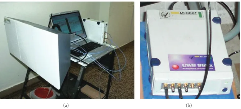
The procedure described in this section was designed for radar signals provided by the M-sequence UWB radar system (Figure 1) and tested for various measurement scenarios (walls of different thickness and material, outdoor or indoor measurements, targets of different size and amount). It consists of eight phases, namely, signal preprocessing, back-ground subtraction, weak signal enhancement, detection, TOA estimation and data-association, wall effect compen-sation, localization, and target tracking. Whole procedure employs 1D signal processing what results in its lower computational complexity in comparison with the imaging methods based on 2D signal processing [10, 11]. In the next paragraphs, a significance of particular phases together with the specific methods providing stable, good, and robust performance for considered through wall applications are outlined.
Raw radar data can be interpreted as a set of impulse responses of surroundings through which the signals emitted
by the radar were propagated. In the case of the M-sequence UWB radar such signals must be at first preprocessed by a time-zero setting. The time-zero is the exact time instant at which the transmitting antenna starts emitting the first elementary impulse of M-sequence (so-called chip). It depends, for example, on the cable lengths, total group delays of radar device electronic systems, and so forth, but especially on the chip position at which the M-sequence generator started to generate the first M-sequence. This position is randomly changed after every power supply reconnection. To find time-zero means rotate all received impulse responses in such a way that their first chips correspond to the spatial position of the transmitting antenna. For finding the number of chips needed for such rotating, we have easily utilized the cross-talk signals between transmitting and receiving antennas [12].
After the phase of raw radar signal preprocessing, a signal-to-noise ratio for radar signals is needed to improve. It is done bybackground subtractionrejecting especially the stationary and correlated clutter such as antenna coupling, impedance mismatch response, and ambient static clutter, and allows the response of moving targets to be detected. The background subtraction methods are based on the esti-mation of the stationary and correlated components of radar signal and are applied for the background estimation mainly in an unknown scene. From a variety of background sub-traction methods we have chosen the exponential averaging because of its robust performance and low complexity [13].
The empirical experiences with processing of the multiple-target scenarios were the reason why the phase of theweak signal enhancementhas been included into the radar signal processing procedure. Whereas in the single-target scenarios the signals scattered by the target are detectable almost in all observation time instants during which the target is moving, in the multiple-target scenarios usually the reflections only from that target situated the most closely to a receiving antenna is seen. In order to solve this problem, we used with advantage the signal normalization based on hierarchical searching of maxima referred to as the advance normalization [14].
Detection is the next step in the radar signal processing which comes after enhancement of weak signal. It represents a class of methods that on base of a statistical decision theory determine whether a target is absent or present in examined radar signals. Between detectors which are able to provide good and robust results in the case of through wall detection by UWB radar, constant false alarm rate (CFAR) detectors belong. They are based on Neymann-Person optimum criterion providing the maximum probability of detection for a given false alarm rate. In considered radar signal processing, the CFAR detector that assumed a Gaussian clutter model has been applied [15].
(a) (b)
Figure1: Experimental M-Sequence UWB radar system: (a) three horn antennas, PC unit and a radar device, (b) detail of the radar device.
detector output. In order to simplify the target localization, such distributed targets [16] are replaced by simple targets, that is, the target position in every observation time instant is given by the only one TOA. This phase of radar signal processing referred to as TOA estimation is performed on the basis of new algorithm, a description of which is given in the next section. The proposed algorithm enables one, in addition to the TOA estimation, to combine TOA estimated from both receiving antennas to such couples from which only the positions of the true targets can be computed during localization phase. This part of algorithm represents a data-associationphase.
The propagation of the electromagnetic waves through wall results in delay time of the signals reflected by the targets moving behind the wall. It means that the TOA estimated by the previous phase of radar signal processing are time shifted because of the wall presence. Their correction is achieved by the subtraction of the mentioned delay time whereby its estimation is the task of thewall effect compensationphase. The method referred to as the target trace correction of the 2nd kind provides promising results in this area [17]. For its utilization the wall parameters, such as permittivity, permeability, and thickness of the wall, must be known in advance.
The estimated and corrected TOA couples are in the following phase of the radar signal processing used as input parameters for localization algorithms. The aim of localization is to determine target coordinates in defined coordinate systems whereby target locations estimated in consecutive time instants create target trajectory. As the considered radar system consists from one transmitting and two receiving antennas, only noniterative direct method of localization can be used. In that case, the target coordinates are simply calculated like intersections of two ellipses given by the correctly associated TOA couples [18].
The particular locations of the target are estimated with certain random error usually described by its probability distribution function. Taking into account this model of the target position estimation, the target trajectory can be further processed by tracking algorithms. They provide a new
estimation of target location based on foregoing positions of the target. Usually, thetrackingresults in the target trajectory error decreasing including trajectory smoothing. In the case of multiple targets, track filtering must also deal with a track maintenance and with the problems of determining which measurements to associate with which targets being tracked. From different tracking algorithms the multiple-target tracking (MTT) system utilizing a linear Kalman filter has been chosen like the method which encloses complex procedure of UWB radar signal processing [19]. Detailed description of the used MTT system is given in [7]. The number of Kalman filters employed in the MTT system is equal to the maximum number of targets to be tracked. In our current work, we have fixed this number at 10, as we consider this amount sufficient for the through wall application.
3. TOA Estimation and Data Association
Because of the simplification, the following approach that combines TOA estimation and data-association into a single phase of UWB radar signal processing is referred to as TOA association. In this section, its basic principle and the algorithm description are presented. Subsequently, the advantages and disadvantages of the proposed TOA-association method are discussed.
P
ro
p
ag
at
io
nt
im
e(
n
s)
Observation time (s)
0 10 20 30 40
20 40 60 80 100
(a)
P
ro
p
ag
at
io
nt
im
e(
n
s)
24 26 32 34 36 38
10 15 20 25
30 30
Observation time (s) 28
(b)
Figure2: Detector output for the first receiving antennaRx1: (a) complete radargram with traces of two moving targets, (b) distributed target trace detail.
position at the detector outputs. They form so-calledtarget trace. In the part of the detector output, where the target should be detected, not only non-zero but also zero samples can be identified. This effect can be explained by a complex target radar cross-section due to the fact that the target size is much bigger than the radar resolution and by taking into account different shapes and properties of the target surface. The set of false alarms is especially due to imperfect signal processing under very strong clutter presence.
The first task of the TOA-association approach consists in substitution of the distributed target with a proper simple target. It enables to estimate one TOA for every target and is done by means of thresholded summation of detector output with interval length corresponding to the assumed size of a target. The higher the threshold value (later labeled asTLIM), the bigger the amount of the false alarms that is suppressed. On the other hand, the weak reflections from targets can be lost, too. Therefore, a smaller threshold setting is recommended seeing that the simple targets improperly indicated by the false alarms can be considerably reduced during the association phase.
The association phase of the proposed approach deals with the task how to recognize all couples of TOA estimated from both receivers in such a way that they produce, after localization process, the true target positions and no the ghost targets. The main idea consists in the utilization of known and short distance between adjacent antennas (in a handheld radar it is usually less than 50 cm) and results in exactly computable and small differences between TOA estimated from both receivers and belonging to the same single target. The difference is calculated on the basis of the triangle inequality arising from the antenna layout and an arbitrary target position (see the appendix).
3.2. Algorithm Description. Let us label the detector output ashkd(t,τ), wheretrepresents the propagation time of radar
signal (along vertical axis of radargram), τ represents the observation time (along horizontal axis of radargram), the subscriptdindicates detection phase, and the superscriptk∈ {1, 2}marks thekth receiver. Then the TOA-association algo-rithm operating in sequence through the vectors hkd(t,τj), for all j (i.e., through all columns of radargram) can be expressed in the following steps.
Step 1. Summation of detector output with interval length corresponding to the assumed size of a target.More precisely, it is a summation ofhkd(t,τ) over propagation time interval
t∈ {ti−Wp+1,ti−Wp+2,. . .,ti}, whereWpdenotes the interval
width.Wpcorresponds to a target size expressed in number of propagation time instants (samples of impulse response). Based on experimental observations of the detector output width (e.g., as is illustrated inFigure 2(b)), we have found thatWp =15 samples for our radar system. As one sample represents a range of 0.066 m, the interval widthWp = 15 samples corresponds to range approximately 1 m what is roughly the size of a person. The summation ofhk
d(t,τ) is given as follows:
hkd(ti,τ)= Wp−1
w=0
hkd(ti−w,τ). (1)
The aim of this step is to eliminate, at least partially, the influence of the wrong results of the detection, that is, the false alarms and the detection results where the target should be detected, but it has not been.
the target presence or absence, respectively. This step can be described by the expression
hkd(t,τ)=
Step 3. Substitution of distributed targets by simple targets. In this step, every continuous TOA interval is substituted by the only one TOA (only one propagation time instant) representing TOA of a potential simple target. On the basis of comparisons between computed and estimated traces we have found that the best representation of the lth simple target is given as follows:
TOAk0,l(τ)=hk
0,l(τ)−tLIM, (3)
wheretLIM=TLIM·tchrepresents the recomputation ofTLIM to propagation time duration by means of the propagation time sampling period tch = 1/ f, where f is a radar internal clock. The subscript 0 indicates that TOAk0,l(τ) is only potential simple target which can be in following steps excluded from further processing. In expression (3),h0,l(τ) is the beginning of thelth TOA interval found by the following procedure:
The variableNtexpresses the total number of the samples of
hkd(t,τ) along the propagation time axis.
Step 4. Artificial widening of potential simple targets. This part of algorithm represents a graphical interpretation of the theorem given in the appendix. The width of artificial widening m expresses the maximum feasible difference between TOA obtained by both receiving antennas and belonging to the same target. This constant term depends on the distance between transmitting and receiving antennas
d = dist(Tx,Rx1) = dist(Tx,Rx2) (not on the target size) and is given as follows:
m=2d
c +tcorr, (5)
wherecis the light propagation velocity andtcorr represents a small correcting factor added with intention to take into
account errors due to measurement and previous phases of radar signal processing. The artificial widening of TOAk0,l(τ) by the valuemenables crossing of searched TOA couples. For that purpose, the variablehkW(t,τ) expressing TOA intervals to be applied within data association phase is created:
hk
where the subscriptWindicates artificial widening.
Step 5. Data association.Data association is made by means of a simple summation of the sequenceshkW(t,τ) fork=1, 2 to the sequencehA(t,τ):
hA(t,τ)=h1W(t,τ) +h2W(t,τ), (7)
where subscript A indicates the association phase. With regard to the hk
W(t,τ) definition, hA(t,τ) ∈ {0, 1, 2, 3} whereas the significance of the particular values of hA(t,τ) is as follows:
1 isolated simple target fromRx1, 2 isolated simple target fromRx2, 3 associated couple of TOA.
(8)
In order to calculate later TOA of simple targets from the associated widened TOA couples, the following variables for every found thelth TOA couple in the observation timeτ
have to be evaluated:
(1)Wl(τ) expressing a width of association given by the length of thelth interval consisting of values “3” in
hA(t,τ);
(2)Cl(τ) expressing a central point of thelth interval; (3)ORx1,l(τ) expressing an order of TOA obtained from
Rx1in the examined couple.
Step 6. Completion of traces based on associated TOA couples found in the previous observation time instant. This stage enables to complete the potential couple of TOA by the missing TOA, if only one receiving channel has detected an echo due to a target. In the case of the isolated simple targets
hA(t,τj)=kfort∈ ti−(m/2),ti+ (m/2), such completion can be realized, if the following condition is fulfilled:
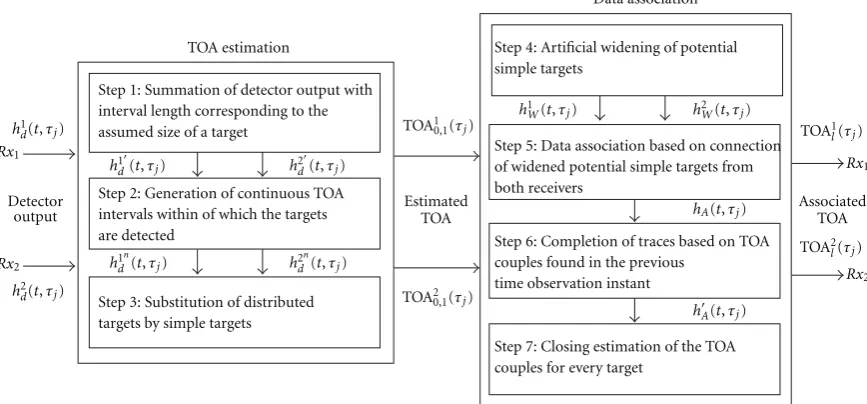
TOA estimation
Step 3: Substitution of distributed targets by simple targets
Step 4: Artificial widening of potential simple targets
Step 7: Closing estimation of the TOA couples for every target
Step 5: Data association based on connection of widened potential simple targets from both receivers
Step 1: Summation of detector output with interval length corresponding to the assumed size of a target
Step 6: Completion of traces based on TOA couples found in the previous
time observation instant Step 2: Generation of continuous TOA
intervals within of which the targets are detected
Figure3: A simplified flowchart of the TOA association method.
Then the isolated target is completed to the associated couple of TOA and the variables of the lth TOA couple from the previous observation time instant are saved for it, that is,:
Wl
Step 7. Closing estimation of the associated TOA couples.It is done by the reverse calculation of simple targets TOAkl(τ) on the basis of the width of associationWl(τ), the central point of associationCl(τ), and the order of TOA fromRx1in the examined coupleORx1,l(τ) according to the expression
TOAkl(τ)=
Then the closing TOA couple appointed as TOA1l(τ) and TOA2l(τ) enables one to estimate the correct position of thelth target in the observation time instant τ by using a suitable localization method based on TOA measurements. A simplified flowchart illustrating the described algorithm is depicted inFigure 3.
3.3. Pros and Cons. The advantage of the proposed TOA association method is that in spite of the step amount it has still a low computational complexity. The average time of whole processing of one impulse response, that is, from raw signal preprocessing until computation of final target positions, is around 0.012 s in the MATLAB programming
environment (Version 7.8.0.347, R2009a). From that, the TOA-association method takes roughly 70%. Inasmuch as the time interval between receiving of the consequent radar signal is approximately 0.074 s for the M-sequence UWB radar under consideration, the whole procedure can be theoretically used for a real-time signal processing.
The losses of targets in some critical situations represent the disadvantage of the proposed TOA-association method. Close-spaced targets and targets moving symmetrically in regard to the antenna layout are examples of such situations. A solution of this problem is the subject of our actual research.
4. Experimental Results
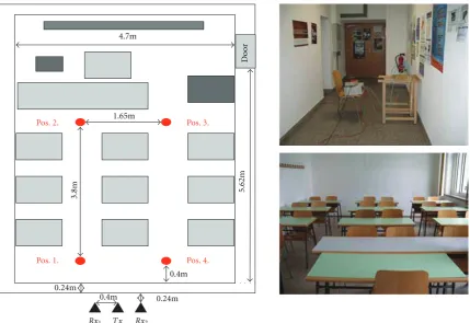
The performance of the proposed TOA-association approach is demonstrated by processing of the real radar signals. The signals were acquired by the aforementioned experimental M-sequence UWB radar equipped with one transmitting (Tx) and two receiving antennas (Rx1, Rx2). The system clock frequency of the radar device is about 4.5 GHz, which results in the operational bandwidth of about DC−2.25 GHz. The M-sequence order emitted by radar is 9, that is, the impulse response covers 511 samples regularly spread over 114 ns. This corresponds to an observation window of 114 ns leading to an unambiguous range of about 16 m.
Pos. 2.
Pos. 1.
Pos. 3.
Pos. 4.
Rx1 Rx2
1.65m 4.7m
3.8m 5.62m
0.4m
0.4m 0.24m 0.24m
Tx
Doo
r
Figure 4: The analyzed scenario with two moving targets: the scenario scheme, the picture of antenna layout, and the picture of the measurement room interior.
The raw radar signals corresponding to the described scenario are depicted in Figures 5(a) and 5(b). In these radargrams, only the cross-talk signal (a direct wave between
Tx andRxk, k = 1, 2) and the reflections of the emitted electromagnetic wave from the wall can be viewed, inasmuch as they are very strong in comparison with weak signals scattered by the moving targets. After utilization of the cross-talk signal for preprocessing (Figures 5(c)and5(d)), the background has been estimated by the exponential averaging. After its subtraction from the raw radar data, the primary traces of moving targets have arisen in the radargrams (Figures 5(e) and 5(f)). For enhancement of the target moving in bigger distance from the radar system, the advance normalization has been applied (Figures 6(a) and 6(b)). In spite of that fact that the obtained signals are noticeably noisy, the CFAR detector, in contrast to the energy detector [16] or the interperiod correlation processor (IPCP) [20], has highlighted the target traces (Figures6(c)and6(d)). The huge amount of the false alarms has resulted in the huge amount of the potential simple targets (Figure 6(e)), but most of them have been successfully suppressed within the association phase (Figure 6(f)). The target locations computed on the basis of estimated TOA couples are depicted inFigure 7(a). The localization errors are larger in the upper part of the picture what results mostly from the larger distance to antennas (Tx has coordinates [0, 0]). Inasmuch as not all wall parameters have been known for the analyzed scenario, the wall effect could not be
compensated and its consequences have also been included in the localization error. The last picture (Figure 7(b)) represents the estimated tracks of the targets as the final results achieved by the described complete radar signal processing procedure. It can be seen from this figure that the estimated tracks correspond with true target trajectories. The correct discrimination between target tracks was made on the basis of association process included in the complex MTT system. The discontinuities of the tracks in the symmetric multitarget situations result from losses TOA in the case of the target trace crossing.
Based on the radar signal processing performed for the analyzed scenario, approximately eight ghost targets could be generated due to the incorrect TOA association. Even though this amount is considerably smaller than the number of the TOA couples improperly indicated by the false alarms and confirmed during association phase, the elimination of the ghosts represents a preferable benefit. It results from the fact that the ghost positions would form two additional continuous trajectories. These could be during the tracking phase evaluated like the other moving targets whereby the wrong TOA couples have created random locations mostly located outside the depicted area.
5. Conclusion
Observation time (s)
Figure5: Raw radar signals: (a) radargram forRx1, (b) radargram forRx2; preprocessed signals: (c) radargram forRx1, (d) radargram for
1
Figure6: Enhanced signals: (a) radargram forRx1, (b) radargram forRx2; detector output: (c) radargram forRx1, (d) radargram forRx2;
TOA-association: (e) joint radargram for bothRxk,k=1, 2 with artificially widened potential simple targets, (f) joint radargram for both
−3 −2 −1 0 0
1 1
2
2 3
3 4
5 6
x-coordinate (m)
y
-c
oor
d
inat
e
(m)
(a)
−3 −2 −1 0 1 2 3
0 1 2 3 4 5 6
x-coordinate (m)
y
-c
oor
d
inat
e
(m)
(b)
Figure7: (a) Target positions estimated by the direct localization, (b) target tracks estimated by the MTT system.
of the complex UWB radar signal processing procedure. The robust estimation of TOA for the multiple distributed targets, the solution of the deghosting task, and from there resulting target localization and tracking improvement belong to its major benefits. The presented experimental results have illustrated the performance of the full procedure by using the scenario for through wall tracking of two moving targets. The comparison of the true and estimated target tracks has confirmed the correctness of the proposed approach.
The TOA-association method has been originally designed for the handheld radar with one transmitting and two receiving antennas. However, the proposed algorithm can be extended directly for multistatic radar systems exploiting an antenna array with the arbitrary number of the receiving antennas placed along a line with small distance between the particular antennas. Thus the basic benefits of the proposed TOA-estimation and data association method would also be advantageous for more complex radar systems.
Appendix
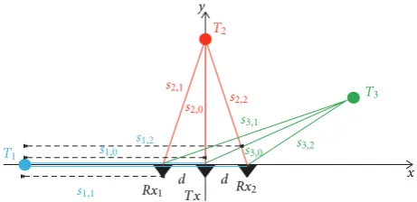
Theorem 1. Let TOAkl represent TOA corresponding to thelth target. Let us assume that TOAkl has been estimated by means of thekth receiving antenna of a radar system if the coordinates of the transmitting antenna (Tx) and the receiving antennas (Rx1, Rx2) are Tx = [0, 0],Rx1 = [−d, 0],Rx2 = [d, 0], respectively. Then, ifd=dist(Tx,Rx1)=dist(Tx,Rx2)is the distance between transmitting and receiving antennas andv
is the electromagnetic wave propagation velocity, the following inequality holds:
∀l TOA2l −TOA1l≤2d
v . (A.1)
Proof. Let us label the distance betweenTx and a targetTl assl,0and the distance between the targetTlandRxk assl,k (Figure 8).
Tx
Rx1 Rx2
T3
T1
T2
x y
s1,2 s2,1
s2,0 s2,2 s3,1
s3,0 s3,2
s1,1 s1,0
d d
Figure8: The scheme of the layout of the radar antennas and the targets in the monitored area.
As it is outlined in Figure 8, in general, a target can be located at three basic different positions inside a monitored area: on thex-axis (targetT1), on they-axis (targetT2), or out of the axes (targetT3). Now, let us consider subsequently all feasible cases of the target position with regard to (A.1):
(1)T1=[x1, 0] As
TOA1
1=s
1,0+s1,1
v =
2s1,1+d
v ,
TOA21=s1,0 +s1,2
v =
2s1,1+ 3d
v .
(A.2)
Then, the following equality holds:
TOA21−TOA11=2d
v . (A.3)
As
TOA12=s2,0+s2,1
v ,
TOA22=s 2,0+s2,2
v , s2,1=s2,2.
(A.4)
Then, the following equality holds:
TOA22−TOA12=0. (A.5)
(3)T3=[x3,y3] As
TOA13=s3,0+s3,1
v ,
TOA23=s3,0 +s3,2
v ,
s3,2−s3,1<2d
(A.6)
(resulting from the triangle inequality in the triangle given byRx1−Rx2−T3).
Then, the following inequality holds:
TOA23−TOA13<2d
v . (A.7)
Based on (A.3), (A.5), and (A.7) the statement (A.1) is proven.
Acknowledgments
This work was supported by the Slovak Scientific Grant Agency VEGA under Contract no. 1/0045/10 and by the Slovak Research and Development Agency APVV under Contract no. LPP-0080-09. This work is also result of the project implementation of the Center of Information and Communication Technologies for Knowledge Systems (Project no. 2622012002) supported by the Research & Development Operational Program funded by the ERDF.
References
[1] S. Nag, M. A. Barnes, T. Payment, and G. W. Holladay, “Ultra-wideband through-wall radar for detecting the motion of
people in real time,” in Radar Sensor Technology and Data
Visualization, vol. 4744 ofProceedings of SPIE, Orlando, Fla, USA, 2002.
[2] M. Richards, Fundamentals of Radar Signal Processing,
McGraw−Hill, New York, NY, USA, 2005.
[3] S. Gezici, Z. Tian, G. B. Giannakis et al., “Localization via ultra-wideband radios: a look at positioning aspects of future
sensor networks,”IEEE Signal Processing Magazine, vol. 22, no.
4, pp. 70–84, 2005.
[4] F. F¨olster and H. Rohling, “Data association and tracking for
automotive radar networks,”IEEE Transactions on Intelligent
Transportation Systems, vol. 6, no. 4, pp. 370–377, 2005.
[5] R. Fleming, C. Kushner, G. Roberts, and U. Nandiwada,
“Rapid acquisition for ultra-wideband localizers,” in
Proceed-ings of the IEEE Conference on Ultra Wideband Systems and Technologies (UWBST ’02), vol. 1, pp. 245–249, Baltimore, Md, USA, May 2002.
[6] A. Rabbachin, J.-P. Montillet, P. Cheong, G. T. F. de Abreu, and I. Oppermann, “Non-coherent energy collection approach
for TOA estimation in UWB systems,” inProceedings of the
IST Mobile & Wireless Communications Summit, Dresden, Germany, June 2005.
[7] J. Khan, S. Niar, A. Rivenq-menhaj, and Y. E. Hillali, “Multiple target tracking system design for driver assistance application,” in Proceedings of the Design & Architectures for Signal and Image Processing, Brussells, Belgium, November 2008.
[8] S. S. Blackman and R. Popoli,Design and Analysis of Modern
Tracking Systems, Artech House, Norwood, Mass, USA, 1993. [9] J. Sachs, R. Herrmann, M. Kmec, and P. Peyerl,
“Modi-fied M-sequence UWB-radar,” inProceedings of the German
Microwave Conference (GeMiC ’06), Karlsruhe, Germany, March 2006.
[10] A. Schmitt and P. Collins, “Demonstration of a network of
simultaneously operating digital noise radars,”IEEE Antennas
and Propagation Magazine, vol. 51, no. 2, pp. 125–130, 2009. [11] H. Wang, R. M. Narayanan, and Z. O. Zhou, “Through-wall
imaging of moving targets using UWB random noise radar,” IEEE Antennas and Wireless Propagation Letters, vol. 8, pp. 802–805, 2009.
[12] R. Yelf, “Where is true time zero?” inProceedings of the 10th
International Conference on Ground Penetrating Radar, pp. 279–282, Delft, The Netherlands, June 2004.
[13] R. Zetik, S. Crabbe, J. Krajnak, P. Peyerl, J. Sachs, and R. Thoma, “Detection and localization of persons behind
obstacles using M-sequence through-the-wall radar,” inSPIE
Defense and Security Symposium, Orlando, Fla, USA, April 2006.
[14] J. Rov ˇn´akov´a,Complete signal processing for through wall target
tracking by M-sequence UWB radar system, Ph.D. dissertation, Technical University of Koˇsice, Letn´a 9, 041 20 Koˇsice, Slovak Republic, August 2009.
[15] P. K. Dutta, A. K. Arora, and S. B. Bibyk, “Towards
radar-enabled sensor networks,” in Proceedings of the 5th
International Conference on Information Processing in Sensor Networks. Special Track on Platform Tools and Design Methods for Network Embedded Sensors, pp. 467–474, Nashville, Tenn, USA, April 2006.
[16] G. A. Van der Spek, “Detection of a distributed target,”IEEE
Transactions on Aerospace and Electronic Systems, vol. 7, no. 5, pp. 922–931, 1971.
[17] J. Rov ˇn´akov´a and D. Kocur, “Compensation of wall effect for
through wall tracking of moving targets,”Radioengineering,
vol. 18, no. 2, pp. 189–195, 2009.
[18] E. Paolini, A. Giorgetti, M. Chiani, R. Minutolo, and M. Mon-tanari, “Localization capability of cooperative anti-intruder
radar systems,” EURASIP Journal on Advances in Signal
Processing, vol. 2008, Article ID 726854, 14 pages, 2008. [19] J. Rov ˇn´akov´a, “Multiple target tracking system for through
wall application,” in Proceedings of the Scientific Conference
of Young Researchers (SCYR ’10), pp. 135–138, Koˇsice, Slovak Republic, May 2010.
[20] H. Hatano, H. Okada, Yamazato T., and M. Katayama, “Performance analysis of UWB impulse radar using parallel
IPCP receiver,” in Proceedings of the 1st IEEE International