R E S E A R C H
Open Access
EXIT-constrained BICM-ID design using extended
mapping
Kisho Fukawa
1*, Soulisak Ormsub
1, Antti Tölli
2, Khoirul Anwar
1and Tad Matsumoto
1,2Abstract
This article proposes a novel design framework, EXIT-constrained binary switching algorithm (EBSA), for achieving near Shannon limit performance with single parity check and irregular repetition coded bit interleaved coded modulation and iterative detection with extended mapping (SI-BICM-ID-EM). EBSA is composed of node degree allocation optimization using linear programming (LP) and labeling optimization based on adaptive binary switching algorithm jointly. This technique achieves exact matching between the Demapper (Dem) and decoder’s
extrinsic information transfer (EXIT) curves while the convergence tunnel opens until the desired mutual
information (MI) point. Moreover, this article proposes a combined use of SI-BICM-ID-EM with Doped-ACCumulator (D-ACC) and modulation doping (MD) to further improve the performance. In fact, the use of D-ACC and SI-BICM-ID (noted as DSI-BICM-SI-BICM-ID-EM) enables the right-most point of the EXIT curve of the combined demapper and D-ACC decoder (Ddacc), denoted asDemDdacc, to reach a point very close to the (1.0, 1.0) MI point. Furthermore, MD provides us with additional degree-of-freedom in“bending” the shape of the demapper EXIT curve by choosing the mixing ratio of modulation formats, and hence the left most point of the demapper EXIT curve can flexibly be lifted up/pushed down with MD aided DSI-BICM-ID-EM (referred to as MDSI-BICM-ID-EM). Results of the simulations show that near-Shannon limit performance can be achieved with the proposed technique; with a parameter set obtained by EBSA for MDSI-BICM-ID-EM, the threshold signal-to-noise power ratio (SNR) is only roughly 0.5 dB away from the Shannon limit, for which the required computational complexity per iteration is at the same order as a Turbo code with only memory-2 convolutional constituent codes.
1 Introduction
The discovery of Turbo code [1] in 1993 is a landmark event in the history of coding theory, since the code can achieve near-Shannon limit performance. It is shown in [1] that the Turbo code composed of memory-4 constitu-ent convo-lutional codes can achieve 0.7 dB, in Signal-to-noise power ratio (SNR), away from the Shannon limit. Various efforts have been made since then to achieve Turbo code-like performance without requiring heavy computational efforts for decoding.
Bit-interleaved coded modulation and iterative detec-tion/decoding (BICM-ID) [2] has been recognized as a bandwidth efficient coded modulation scheme, of which transmitter is comprised of a concatenation of encoder and bit-to-symbol mapper separated by a bit interleaver. Iterative detection-and-decoding takes place at the
receiver, where extrinsic log likelihood ratio (LLR), obtained as the result of the maximum a posteriori
probability (MAP) algorithm for demapping/decoding, is forwarded to the decoder/demapper via de-interleaver/ interleaver and used as the a priori LLR for decoding/ demapping according to the standard turbo principle.
Performances of BICM-ID have to be evaluated by the convergence and asymptotic properties [3], which are represented by the threshold SNR and bit error rate (BER) floor, respectively. In principle, since BICM-ID is a serially concatenated system, analyzing its performances can rely on the area property [4] of the EXtrinsic Infor-mation Transfer (EXIT) chart. Therefore, the transmis-sion link design based on BICM-ID falls into the issue of matching between the demapper and decoder EXIT curves.
Various efforts have been made seeking for better matching between the two curves to minimize the gap, while still keeping the tunnel open, aiming, without requiring heavy detection/decoding complexity, at * Correspondence: [email protected]
1
School of Information Science, Japan Advanced Institute of Science and Technology (JAIST), 1-1 Asahidai, Nomi, Ishikawa, 923-1292, Japan Full list of author information is available at the end of the article
achieving lower threshold SNR and BER floor. In [5], ten Brink et al. introduced a technique that makes good matching between the detector and decoder EXIT curves using low density parity check (LDPC) code in multiple input multiple output (MIMO) spatial multi-plexing systems.
It has long been believed that for 4-quadrature ampli-tude modulation (4-QAM), the combination of Gray mapping and Turbo or LDPC codes achieves the opti-mal performance. However, Schreckenbach et al. [6] propose another approach towards achieving good matching between the two curves by introducing differ-ent mapping rules, such as non-Gray mapping, which allows the use of even simpler codes to achieve BER pinch-off (corresponding to the threshold SNR) at an SNR value relatively close to the Shannon limit.
Another technique that can provide us with the design flexibility is extended mapping (EM) presented in [7,8] where with 2m-QAM,ℓmap bits (ℓmap >m), are allocated to one signal point in the constellation. With EM, the left-most point of the demapper EXIT function has a lower value than that with the Gray mapping, but the right-most point becomes higher. With this setting, the demapper EXIT function achieves better matching even with weaker codes such as short memory convolution codes as shown in [7]. However, there is a fundamental drawback with the structure shown in [7]; it still suffers from the BER floor simply because the demapper EXIT curve does not reach the top-right (1.0,1.0) MI point.
In [9], Pfletschinger and Sanzi suggest that by using the memory-1 rate-1 recursive systematic convolutional code (RSCC), referred to as D-ACC located immediately after the interleaver, the error floor can be eliminated. Furthermore, it was shown by [10] that by replacing the RSCC-coded bitsbu(P) with the accumulated bitsbc(P)
at everyPbit-timings, the technique of which is referred to as inner doping with doping ratio (1:P), the EXIT curve ofDemDdacccan be flexibly changed.
Several techniques have been proposed to determine optimal labeling pattern for the modulation (bit pattern vector allocated to each constellation point). The ideas of binary switching algorithm (BSA), which aims at labeling costs optimization, are presented in [6,11]. However, the BSA based labeling optimization evaluates the labeling cost assuming that fulla prioriinformation is available. Hence, this approach only aims at lifting up as much the rightmost point of the demapper EXIT curve as possible. Yang et al. [12] introduce adaptive binary switching algorithm (ABSA) to obtain optimal labeling pattern, where optimality is defined by taking into account the labeling costs at multiplea priori MI points. Hence, ABSA changes the shape of the demap-per EXIT curves more flexibly than BSA. However, the optimal labeling obtained in ABSA is on given
code-basis since the code parameter optimization is not included in the ABSA iterations.
In our previous publication [13], we introduced a BICM-ID technique that uses even simpler codes, single parity check code (SPC) and irregular repetition code (IRC), combined with EM. For the notation simplicity, we refer our proposed BICM-ID structure in [13] to as SPC-and-IRC aided BICM-ID with EM (SI-BICM-ID-EM). We investigated in [14] that linear programming (LP) technique can be applied for SI-BICM-ID-EM to determine the optimal degree allocations for the IRC code with the aim of achieving desired convergence property. Moreover, in [15] we proposed a combined use of modulation doping (MD), originally proposed in [16,17], which mixes the labeling rules for the extended non-Gray mapping and the standard Gray mapping at a certain ratio. The technique proposed in [15] helps the left-most point of the demapper slightly be lifted up to initiate the LLR exchange between the demapper and the decoder. This technique gives the additional degree-of-freedom in “bending” the shape of the demapper EXIT curve by choosing the mixing ratio and hence the left-most point of the demapper EXIT curve can be flex-ibly lifted up/pushed down. This article proposes a com-bined use of SI-BICM-ID-EM with D-ACC and MD. The D-ACC aided SI-BICM-ID-EM is referred to as DSI-BICM-ID-EM, and MD aided DSI-BICM-ID-EM is referred to as MDSI-BICM-ID-EM later on.
The primary goal of this article is to create a design framework for the optimization of SI-BICM-ID-EMa by combining those techniques into a unified iterative algo-rithm. To achieve the goal described above, this article proposes a new labeling pattern optimization technique, EXIT-constrained Binary Switching Algorithm (EBSA). The gap between the two EXIT curves is taken into account in arepeat-until loop that controls the EBSA algorithm. Hence, the process for determining the opti-mal degree allocation using LP [13,14] is also included
in therepeat-until loopin EBSA.
The results of simulations show that near-Shannon limit performance can be achieved with the proposed techniques; BER simulation results show that 4-QAM EM with ℓmap= 5, the threshold SNR is only roughly 0.5 dB away from the Shannon limit with MDSI-BICM-ID-EM, for which required computational complexity forDemDdacc is almost the same as a Turbo code with only memory-2 convolutional constituency codes, per iteration.
Section 5.1, convergence property of the proposed schemes described to confirm the effectiveness of EBSA; in Section 5.2, the results of BER performance evalua-tions are presented. In Section 6, computational com-plexity with the proposed technique is assessed briefly. Finally, we conclude this article in Section 7 with some concluding statements.
2 System model 2.1 Transmitter
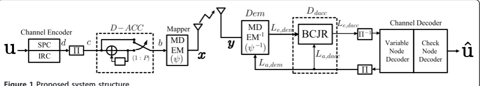
Figure 1 describes the system model considered in this article. The SI-BICM-ID-EM technique, which this arti-cle is based on, is detailed in [13] including its sche-matic diagram. Therefore, it is only summarized in this section. The binary bit information sequence uto be transmitted is encoded by, first, a single parity check code where a single parity bit is added to every dc - 1
information bits, followed by a repetition code. dc is
referred to as check node degree.
The repetition times dv, referred to as variable node
degree, may take different values in a block (transmis-sion frame); if dv takes several different values in a
block, such code is referred to as having irregular degree allocations. It is assumed throughout this article thatdc
takes only one identical value as in [5]. The rate of the code is
R= (dc−1)
and the spectrum efficiency is
η=map·R
bits per symbol, where ai represents the ratio of
vari-able nodes having degree dvi in a block and M is the
number of node degree allocations.
The coded bit sequence is bit-interleaved, and seg-mented into ℓmap-bit segments, and then each segment is mapped on to one of the 2m constellation points for
modulation. The complex-valued signal modulated according to the mapping rule is finally transmitted to the wireless channel. Since ℓmap >m with EM, more than one label having different bit patterns in the seg-ment are mapped on to each constellation point. How-ever, there are many possible combinations of the bit patterns, hence determining of the optimal labeling pat-tern plays the key role to achieve limit-approaching performance.
2.2 Channel
This article assumes frequency flat additive white Gaus-sian noise (AWGN) channel. If the channel exhibits fre-quency selectivity due to the multipath propagation, the receiver needs an equalizer to eliminate the inter-symbol interference. Combining the technique presented in this article with the turbo equalization framework [18,19] is rather straightforward. It is assumed that transmission chain is properly normalized so that the received
SNR = 1/σn2; with this normalization, we can properly
delete the channel complex gain term from the mathe-matical expression of the channel. The discrete time description of the received signaly(k) is then expressed by
y(k) =x(k) +n(k), (3)
where, withkbeing the symbol timing index. xis the transmitted modulated signal with unit power and expressed as
x=ψ(s), (4)
where s= [b1b2. . .bmap] is labeling pattern and ψ(·) is
the mapping function as indicated in Figure 1. nis zero mean complex AWGN component with variance σn2
(i.e.,〈|x(k)|2〉= 1,〈n(k)〉= 0 and n(k)2
=σn2) for∀k.
2.3 Receiver
At the receiver side, the iterative processing is invoked, where extrinsic information is exchanged between the demapper and decoder. Using received signal sampley
(k) and thea prioriLLR fed back from the decoder, the
of thevth bit in the labeling vector in the symbolx(k) =
where S0 (S1) indicates the set of the labeling pattern s having the vth bit being 0(1), and La,Dem(br(s)) is the
demapper’sa prioriLLR fed back from the decoder cor-responding to therth position in the labeling patterns.
Decoding takes place segment-wise where, because of the irregular code structure, the variable node degrees dvi have different values segment-by-segment. Structure
of the decoder as well as decoding algorithm is detailed in the previous publications, e.g., in [13,14,20]. There-fore, only summary of the algorithm is provided in this article.
The dvi bits constituting one segment, output from
the de-interleaver are connected to a variable node, and
dcvariable nodes are further connected to a check node;
those demapper output bits in one segment, connected to the same variable node decoder, are not overlapping with other segments. Therefore, no iterations in the decoder are required [13,14,20]. The extrinsic LLR update for a bit at the check node is exactly the same as the check node operation in the LDPC codes, as
Le,Cnd,v =
where ∑⊞ represents the box-sum operator [5]. La, Dec, =Le,Dem, is thea priori LLR provided by the th
variable node. Le,Cnd,ν is the extrinsic LLR fed back to the νth variable node, where it is further combined with (dvi –1) a priori LLRs forwarded from the demapper
via the deinterleaver, as
Le,Dec,ν=Le,Cnd,ν+ dvi
ω=1,ω=ν
La,Dec,ω (8)
This process is performed for the other variable nodes in the same segment having the variable node degree dvi, and also for all the other segments independently in
the same transmission block. Finally, the updated extrin-sic LLRs obtained at the each variable node are inter-leaved, and fed back to the demapper. For the final bit-wise decision,a posteriori LLR output from the decoder is used.
2.4 DSI-BICM-ID-EM
Reference [20] proposes a combined use of D-ACC with SI-BICM-ID-EM (DSI-BICM-ID-EM).bThe purpose of introducing D-ACC is to lift the right-most point of demapper EXIT curve up to reach the (1.0,1.0) MI point so that the BER floor with SI-BICM-ID-EM can be eliminated. In this system structure, D-ACC is placed between the interleaver and mapper as shown in Figure 1 of [20]. The coded bit sequence is bit-interleaved, and input to the D-ACC with doping ratio of (1:P). To keep the D-ACC’s code rate equal to one, the interleaver’s output is replaced by a D-ACC-coded bit at everyPth bit.
2.5 MDSI-BICM-ID-EM
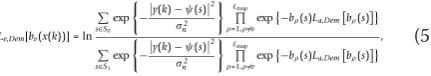
This article also applies the idea of mixing modulation symbols of EM and standard Gray mapping at a certain ratio, original idea of which was first introduced in [17,21]. This technique is referred to as MD. Since the demapper EXIT function with Gray mapping is comple-tely flat for 4-QAM, its left-most point has obviously higher MI than with EM mapping. The left-most point of demapper’s EXIT curve is lifted up with MD and the amount depends on the mixing ratio. Figure 2 shows a block diagram of the MD system. The spectrum effi-ciency of the system then becomes (D · m + (1 - D) · ℓmap) · Rbits/symbol, whereDand (1 -D)are the ratios of the symbols with doped (Gray) and EM, respectively, in one transmission frame.
3 EXIT analysis
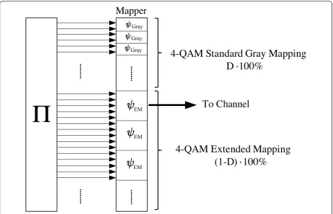
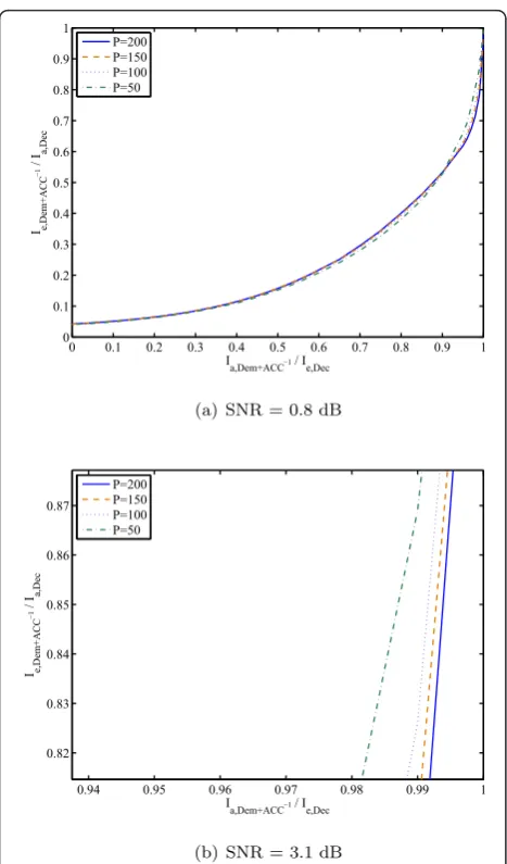
For the decoder of D-ACC, denoted asDdacc, the Bahl-Cocke-Jelinek-Raviv (BCJR) algorithm is performed at the receiver. Figure 3 show the EXIT curves forDemD -dacc for P = {50,100,150, 200}: Figure 3a depicts the entire portion of the curves, and Figure 3b zooms up their right-most parts. It is observed that all demapper curves can achieve the right-most point close enough to the (1.0,1.0) MI point. Furthermore, the Pvalue affects the shape of the demapper curve. It can be observed in Figure 3b that the larger the P value, the sharper the decay of the curve around the (1.0,1.0) MI point.
Since detailed investigation for the effect of EM on the shape and the demap-per’s EXIT function is provided in the previous publications, e.g., [20], they are not pro-vided in this article. For those readers who are inter-ested in this issue can refer [7,13,20].
whereIa,visa prioriMI andIe,vis its output extrinsic
MI. J(·) andJ-1(·) are the functions that convert the square-root variance of LLR to its corresponding MI, and its inverse function, respectively [3]. Obviously, (9) is corre-sponding to the second term of the right hand side of (8) for LLR update, with whichIa,v= Ie,dem, whereIe,demis the
demapper output extrinsic MI. The EXIT function of the SPC decoder can be approximated by [22]
Ie,Cnd= 1−J
dc−1·J−1(1−Ia,cnd)
, (10)
where
Ia,cnd=J
dv·J−1(Ia,Dec)2
. (11)
The EXIT function of the whole decoder comprised of the variable and check node decoders can be calculated by combining (10) and (11) [5], as
Ie,Dec=J
(dv−1)·J−1(Ia,Dec)2+J−1(Ie,Cnd)2
,(12)
with Ia,Dec= Ie,dem. Since the SI-BICM-ID-EM uses
irregular structure of the repetition code, its EXIT func-tion depends on the degree distribufunc-tion ai of the
variable node dvi. Our previous publication [13] showed
that the EXIT function of the whole decoder with the proposed structure can be obtained by weighting the segment-wise EXIT functions, as
Ie,Dec=
iai·dvi·J
(dvi−1)·J−1(Ia,Dec)
2+J−1(I e,Cnd)2
iai·dvi
, (13)
Hence, it is found that the key of achieving the best matching between the demapper and the decoder EXIT curves is to jointly optimize the labeling pattern and the variable node degree distributionai.
4 Framework for EBSA-based DSI-BICM-ID-EM design
4.1 Optimal node degree allocation using LP
In [14], we showed that the optimal node degree alloca-tions problem can be formulated as
Minimize
M
i=1
aidvi
Subject to
M
i=1
ai·dvi
−J
(dvi−1)·J−1(Ie,Dem,w)2
+J−1(Ie,Cnd,w)2
+Ia,Dem,w+εw
≤0 (for 1≤w≤N)
and
M
i=1
ai= 1
where the optimization variables are ai, (i = 1,...,M)
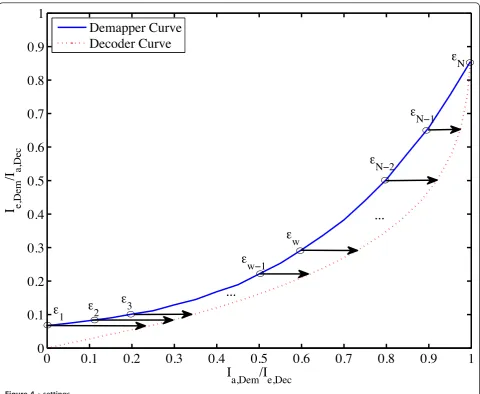
and w denotes the pre-defined horizontal gap width between the demapper and the decoder EXIT curves and Nis the number of the MI constellation points as shown in Figure 4.
More details are given in Appendix 1. Furthermore, to find the optimal check node degree dc, this article
pro-poses a brute-force search (all possible value search),cas summarized in Algorithm 1.
Algorithm 1 Optimal degree allocation algorithm
Initialize dvi and aivalues. fordc= 2tomaxdc do
PerformLP for Equation (14) with fixed dc and
obtain optimal distributionaifor each dvi.
Calculate code rateRusing dc,dvandai. end for
Find dcopt andaoptachievingR®max.
return dcopt and aopt.
4.2 EBSA framework
In [12], Yang et al. introduce the idea of Adaptive BSA (ABSA) which takes into account the costs at multiplea prioriinformation points. The gap width between the demapper and the decoder EXIT curves is also taken into account, given the decoder EXIT curve. ABSA then obtains the optimal doping ratio in conjunction with determining the optimal labeling pattern. Hence, opening of the convergence tunnel until the (1.0, 1.0) MI point is guaranteed with this technique. However, ABSA does not change the code parameters in optimization process, and therefore, optimality is onlyon given code-basis.
In this section, a novel technique EBSA is introduced. EBSA aims jointly to optimize labeling patterns, doping ratio, and code parameters using LP described in Sec-tion 4.1. Hence, EBSA achieves close matching between the demapper and the decoder curves, while it guaran-tees the opening of the convergence tunnel until the (1.0, 1.0) MI point. In a graphical expression, as pre-sented in Figure 5, EBSA takes into account the horizon-talandvertical gap widths at the multiple pre-defined a priori MI points, which is also effective in making a rea-sonable compromise between performance and com-plexity due to the turbo iterations.
Since both the ABSA and EBSA algorithms, in com-mon, are based on the BSA, as well as the same cost definition, BSA and the cost are summarized in Appen-dices 2 and 3, respectively, for the completeness of the article. This article’s proposed EBSA algorithm is sum-marized in Algorithm 2. It should be noticed that the processes for determining the optimal doping ratio, the
dc value, and the LP based code parameter optimization
are all included in a single repeat-until loop. This indi-cates that the code parameters are also changed in the EBSA framework.
It should be further noticed that the horizontal and
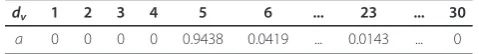
verticalgap widths evaluation, as descriptively summar-ized in Figure 5, is included in the repeat-until loop. With the EBSA framework, the labeling pattern used in the LP-based degree allocation optimization for DSI-BICM-ID-EM are obtained by lowering the cost of Zmap−1 (at right-most MI point corresponding to the
case with fulla prioriinformation) as much as possible, while still keeping the vertical gap smaller than the pre-defined valueδw. Hence, other costs Z0,. . .,Zmap−2 are
ignored in the LP based optimization.
5 Numerical results
5.1 Convergence property analysis
MDSI-BICM-ID-EM, but also to other structures, as described in Endnote “a” in Section 1. To demonstrate the performances superiority with the optimization tech-niques described in this article, EXIT curves were calcu-lated for several designs described in the previous sections, aiming at the turbo cliff to happen at SNR = 0.8 dB and 3.1 dB, as examples.
5.1.1 SI-BICM-ID-EM with node degree optimization using LP
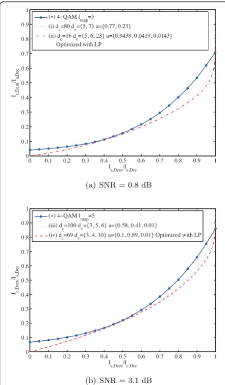
Tables 1 and 2 show the node degree allocations before and after performing LP forℓmap= 5 and SNR = 0.8 dB, where the simplex algorithm was used as a tool for LP. Table 3 shows the initial values of for the optimiza-tion. The expected
Algorithm 2 EXIT-constrained binary switching algorithm
(EBSA)λ= [λ0λ1· · ·λmap−2λmap−1] = [0 0· · ·0 1]
Initialization: Generate labeling patternsrandomly as well as degree distributiondvempirically
for P = 2and dc = 2to maxP and max dc,
respec-tivelydo repeat
Draw demapper EXIT curve based on the given labeling pattern s obtained as the result of the latest iteration
fori= 1toNmaxddo
Conduct BSA with Zmap−1=Z¯ and
Zhmap−1=Z¯h(h= 0,. . .2map−1) end for
Draw the demapper’s EXIT curve using the obtained labeling pattern.
Draw the decoder’s EXIT curve using degree dis-tribution using LP for Equation (14) with the obtained labeling pattern.
if*The vertical gap δ in the range of MI(Zq ± ΔZq)e, 0 ≤q≤ℓmap–1, aroundZq as shown in Figure 6
is larger than desired valueδq then lq=lq–1
end if
Select the labeling pattern and decoder node dis-tribution that has minimum gap.
untilGap between the demapper and decoder EXIT
curve becomes smaller than the threshold for each MI points tested.
end for
Select the optimal parameter set that minimizes the gap
intersection point is set atIa,Dem = 0.9999. With the
same initial degree allocations and settings, EBSA was performed for SNR = 3.1 dB. Figure 7 show with and
without optimization the EXIT curves for SNR = 0.8
dB and 3.1 dB, respectively, for SI-BICM-ID-EM. In the case without degree allocations optimization, the empiri-cally obtained distribution shown in [13,15] were used, which are indicated by (i) and (iii) in the figure for SNR = 0.8 dB and 3.1 dB, respectively.
It is found by carefully looking at the right-most part of the curves that the intersection point of the (ii)-(iv) decoder curves and the demapper curve indicated by (*) in the figure are found to be slightly closer to the extrinsic MI = 1.0 than the empirically designed case. Figure 5Gap checking in EBSA.
Table 1 Initial degree distributions
dv 1 2 3 4 ... 6 7 8 9 30
a 1
30 1 30
1 30
1
30 ...
1 30
1 30
1 30
1 30
1 30
Table 2 Optimized degree distributions
However, the rate of the code obtained by LP is slightly lower than the rate of the code with empirically obtained degree allocation, and the intersection point of the two EXIT curves is still quite apart from the (1.0,1.0) MI point. Therefore, LP alone can lower the BER floor, but cannot increase the spectrum efficiency in those cases.
5.1.2 DSI-BICM-ID-EM with node degree optimization using LP technique
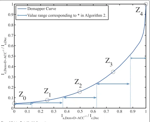
To eliminate the BER floor, we conducted a node degrees optimization for DSI-BICM-ID-EM aiming at better matching of the two EXIT curves. Figure 8a shows the EXIT curve withDemDdaccfor SNR = 0.8 dB. In addition, the decoder EXIT curves are also drawn
using the degree distribution obtained by using LP with the settings given in Table 3. Note that the doping rate Pwas determined empirically in this case. It can be observed from Figure 8a that theDemDdaccand decoder EXIT curves closely match except the left-most region.
Similar result can be observed from Figure 8b, where optimization was performed for SNR = 3.1 dB. Both in Figures 8a,b, the two EXIT curves intersect at a point very close to the (1.0,1.0) MI point. Therefore, no BER floor (or, at least invisible in the BER value range shown in the figure) and higher spectrum efficiency compared to the empirically designed SI-BICM-ID-EM are expected.
5.1.3 MDSI-BICM-ID-EM with EBSA
Figure 9 shows the EXIT chart of DSI-BICM-ID-EM obtained by EBSA. Note thatandδsettings shown in Tables 3 and 4 were used, respectively. It can be observed that as the result of EBSA, the shape of the
DemDdaccEXIT curve indicated by (■) in Figure 8a is
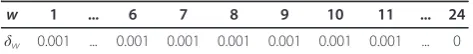
Table 3settings
w 1 ... 6 7 8 9 10 11 ... 24 w 0.001 ... 0.001 0.001 0.001 0.001 0.001 0.001 ... 0
changed to that shown in Figure 9. Notice that the obtained demapper EXIT curve starts from the the (0.0,0.0) MI point. Therefore, no node degree distribu-tion that can initiate the LLR exchange was found by LP for any given initial and δ settings. This is because EBSA aims to push down the DemDdacccurve by allow-ing the gap width lower than δw for 1≤ w≤ N.
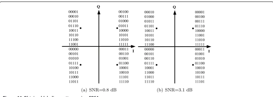
There-fore, we apply EBSA to MDSI-BICM-ID-EM in order to slightly lift up the left-most point of theDemDdaccEXIT curve. Figure 10 shows the EXIT curves, where we apply EBSA to MDSI-BICM-ID-EM with the MD ratio 0.012 and 0.01 for SNR = 0.8 dB and 3.1 dB, respec-tively. In the EXIT analysis in those cases, the labeling patterns shown in Figure 11, obtained as the result of EBSA, was used.
From Figure 10a, very close matching between the
DemDdaccand the decoder EXIT curves can be observed
from the starting point to the end. Moreover, now the
DemDdacc EXIT curve starts from (0,0.0064) and thereby, LLR exchange can be initiated, and hence the trajectory can reach the target MI point close enough to the (1.0,1.0) point. Similar characteristics can be observed in Figure 10b, where the optimization was per-formed for SNR = 3.1 dB.
5.2 BER performances
Figure 12 shows the BER performance using the pro-posed optimization techniques at the target SNR ≈ 0.8 dB. It is found that for SNR = 0.8 dB when only node degree distribution optimization by LP was performed for SI-BICM-ID-EM (indexed by (*) and (ii) in the fig-ure), lower bit error floor can be achieved compared to empirically designed case ((*) and (i)) [13,15]. However, due to the decrease in the code rate, the Shannon limit Figure 7EXIT curves of SI-BICM-ID-EM with and without LP
SNR becomes even lower than the empirically designed case (1.5 dB away from the limit with (*) and (i), while 1.6 dB away with (*) and (ii)). The curve indexed by (*) and (v) shows the BER performance, where node degrees optimization was performed to DSI-BICM-ID-EM. With this technique, turbo cliff happens about 0.8 dB away from the Shannon limit (corresponding to the curve indicated by (■) and (v) in the figure.). Further-more, it is found that, by using the D-ACC, BER floor can be completely eliminated (or, at least invisible in the BER value range shown in the figure).
The BER performance with MDSI-BICM-ID-EM are shown by the curve indicated by (▼) and (vii), where EBSA and MD were utilized. The best result among
those tested cases achieves the threshold SNR of around 0.5 dB away from the Shannon limit, for which para-meters are shown below the figure caption. It should be noted that approximately 300 iterations were needed for the BER simulations when SNR is around the threshold. Similar performance can be observed with the BER curves yielding turbo cliff at around 3.1 dB as shown in Figure 13.
6 Complexity assessment
With ℓmap= 5, there are 32 labeling patterns in total, where each of the setsS0 andS1 contains 16 patterns. Hence, the probabilities for the 16 patterns have to be summed up when calculating the numerator and the denominator of (5). Since the BCJR algorithm requires forward and backward processing and each state emits two branches corresponding to the systematic input being 0 and 1, the computational complexity for the demapper having 16 labeling patterns both in the Figure 9EXIT curves of DSI-BICM-ID-EM using EBSA at SNR = 0.8 dB.
Table 4δsettings
w 1 ... 6 7 8 9 10 11 ... 24
numerator and the denominator is equivalent to the decoding complexity of memory-3 convolutional code using the BCJR algorithm (3 = log2(8) = log2(162)). Furthermore, since Turbo code requires at least two constituency codes [1], the complexity estimated above is also roughly equivalent to that required by a Turbo code having two memory-2 constituent convolutional codes (2 = log2(4) = log2(82)).
The decoding complexity forDdaccis negligible and so is the case of the decoding complexity for the SPC and IRC codes as well, because no iterations are needed in the decoder, as described in Section 2. Therefore, it can be concluded that with ℓmap = 5 the computational complexity required for the proposed MDSI-BICM-ID-EM technique is almost equivalent to that with a Turbo code having memory-2 constituent convolutional code. It should be emphasized here that the Turbo code pro-posed in [1] uses two memory-4 convolutional codes, which requires roughly 4 times as large complexity as that with the proposed technique withℓmap= 5. Never-theless, the proposed technique can achieve better BER performance than the Turbo code presented in [1]. This is mainly because the EBSA algorithm jointly optimize the labeling patterns and degree allocations as a sys-tematic framework. Numbers of the additions, multipli-cations, and divisions required for the demapping process are summarized in Table 5.
7 Conclusions
This article has proposed a design framework, EBSA, and applied it to our proposed BICM-ID techniques, SI-BICM-ID-EM, DSI-BICM-ID-EM and MDSI-BICM-ID-EM. Since EBSA takes into account the horizontal and verticalgap widths between theDemDdaccand decoder’s EXIT curves at the pre-defined several MI points, it can determine the optimal labeling pattern for EM and degree allocations simultaneously. In fact, when EBSA is Figure 10Demapper’s EXIT curve of MDSI-BICM-ID-EM using
EBSA.
applied to DSI-BICM-ID-EM, two curves exactly match, and surprisingly the left-most point of the EXIT curve ofDemDdaccis determined to be the (0.0, 0.0) MI point, and hence LLR exchange can not be initiated. To avoid this situation, this article introduced the MD technique, by which the left-most point of the DemDdacc EXIT curves can be lifted up slightly while the other part still exactly matched. As the result, very close-Shannon limit performance can be achieved without requiring heavy computational burden withℓmap = 5 EM 4-QAM; the complexity is almost the same level as a Turbo code with only memory-2 constituency codes.
The following three issues have to be noted in con-cluding this article, since this special issue has two focal points,“Algorithm and Implementation Aspects":
•The proposed EBSA is applicable to BICM-ID techni-ques using other codes, so far as the degree allocation optimization can be performed using LP. LDPC-aided BICM-ID [23] and irregular convolutional code-aided BICM-ID [16] belong to this category. This is the rea-son why call EBSA “framework” rather than “technique”.
• Application of the EBSA framework to higher order modulation is left as future study.
Appendix 1: Node degree optimization using LP
The objectives of the node degree optimization can be defined as follows.
1. Code rate has to be lower than but as close to the capacity as possible.
2. Keep the convergence tunnel open between the demapper and decoder EXIT curve until the desired intersection point and the point should be as close to the (1.0, 1.0) MI point as possible.
3. Total of node degrees distributions has to be always 1.
Givenℓmap, the criterion can be written as Findaifor eachdvi
Such that Rate = (dc−1)/(dc M
i=1
ai·dvi)→Maximized
Subject to M
i=1
ai= 1,
andIe,Dec>Ia,Dec=Ie,Dem,
(15)
where Ie,Dec, Ia,Dec and Ie,Dem denote the decoder
extrinsic MI, the decodera prioriMI and the demapper extrinsic MI, respectively. Now, assume that the check node degreedc is a constant. Then, the optimality
cri-teria of (15) is equivalent to
Findaifor eachdvi
where the, index w is introduced, representing the pre-defined MI constraint points, and also another para-meterw representing the acceptable gap betweenIe,Dec andIa,Dec, such that
Ie,Dec,w−Ia,Dec,w≥εw≥0 for 1≤w≤N, (17)
whereNis the total number of the constraint points on the EXIT curve, indexed byw. Equation (17) can be further modified to:
Therefore, (17) can be regarded as the linear function ofai. Now the optimality criterion can be rewritten with
the parameters and indexes defined above, as
Minimize
Now, given the fact that the optimization parameter in (19) is only ai and the other terms are constant and
furthermore, the index and constraints are both linear function of the optimization variableai. Hence, the
pro-blem can be solved by using LP techniques.
Appendix 2: Summary of BSA
Labeling pattern shown in [13] for DSI-BICM-ID-EM is obtained by using binary switching algorithm (BSA) for optimization where labeling cost function defined in this
section is used. In [6], labeling cost refers to pairwise error probability in AWGN channels with fulla priori
information. Assuming that the bit to be detected fulla priori MI for the rest of the ℓmap –1 bits is available, the average pairwise error probability Zmap−1 between
the two symbols, originally transmitted symbolsand the other symbolsŝ, is given by,
Zmap−1=
where function μ(·) returns the constellation point corresponding to the labeling patterns svand ŝvbeing
thevth bit being 0 and 1. The average pairwise probabil-ity given by (20) is used as a cost function, which can be further decomposed as a sum of the cost functions for each fixed symbol sh, given the fact that
Zmap−1=
Algorithm 3 Binary switching algorithm (BSA) repeat
Initialization: generate labeling pattern randomly. Select the symbolshigh which has the highest cost
Zh
map−1.
Find the symbolslow which can achieve maximum
reduction of the total
cost Zmap−1 by swapping the positions ofshighand slow.
ifslowexists.then
Swapshigh andslow.
Update Zmap−1 according to the new labeling
pattern.
else
Set the symbol with the second highest cost as
shigh. end if
untilThere is no pair of symbols to switch
A problem with this approach is, however, that the cost is calculated assuming the availability of a full a prioriinformation and thus, Zmap−1 affect only the right
most point of theDemDdaccEXIT curve, and it does not consider the matching between the demapper and deco-der EXIT curves. This approach is reasonable only when the objective is to force the right-most point of the demapper curve to reach as close to the (1.0,1.0) MI point as possible. However, this article has already pro-posed the use of D-ACC which already makes it possible Table 5 Calculation cost of 4-QAM EM
Addition/Subtraction Multiplication Division
4-QAM EM 2map2
for the demapper EXIT curve to reach a point close enough to the (1.0,1.0) MI point. In the subsection 4-D, a novel algorithm, EBSA, is introduced to obtain a label-ing pattern aimlabel-ing at better matchlabel-ing between the two curves, assuming the use of D-ACC.
Appendix 3: Cost functions for ABSA and EBSA
The cost definition commonly used by ABSA and EBSA are summarized below. Given ℓmap, the number of the known bitsqsatisfies
q= 0, 1,. . .,map−1. (22)
For the labeling costZqwith theq known bits having
theira priori MI = 1,Zqcan be expressed as
Furthermore, sinceZq can be decomposed into
sym-bol-wise cost Zhq, as The labeling cost matrix forℓmapis defined as anℓmap × 2 map matrix, given by
sponds to the case where the all bits in the label are one, since the symbol-wise cost is measured from a bit in the pattern being zero, and the larger the
μ(shv)−μ(ˆshv)2 value, the lower the cost. Furthermore, there are no terms summed up in the second summa-tion in (20) and (21). Hence, all the costs in the
(2map−1)th low are zero, i.e,
vector Zˆ for each q is calculated by simply summing the column vector ofZas
ˆ
Those costs affect the shape of the demapper EXIT curve. Figure 6 shows an intuitive example forℓmap= 5.
Now weighting vector l is introduced to take into account the fact that which cost is important from the viewpoint of the matching between the two EXIT curves. The weighted cost Z¯ (scaler) is defined by using the weight vectorl, as
¯
Z=Zˆλ=Zˆλ0λ1· · ·λmap−2λmap−1
t
. (29)
Also, usingl, symbol wise weighted cost vector Z¯ can be calculated as
The proposed technique is also applicable to other BICM-ID techniques, so far as they use LP for degree allocation optimization. LDPC aided BICM-ID as well as irregular convolutional code aided BICM-ID belong to this class. This is the reason on why we call the technique proposed in this article“framework”. b Com-bined use of D-ACC with BICM-ID itself was first pro-posed by [9]. The technique is also used in [12] to determine the optimal doping rate when it is combined with BSA. cdc has indirect effect to the LP
optimiza-tion, but to the code rate. dSchreckenbach et al. [6] show thatNmax= 100 is enough. eThe range is defined as: MI(Zq +ΔZq) for q =0, MI(Zq ± ΔZq) for 1 ≤ q ≤ ℓmap – 2 and MI(Zq – ΔZq) for q = ℓmap – 1, where
Δ= 1/(ℓmap –1).
Acknowledgements
thankful for valuable technical comments and suggestions given by Mr. Takehiko Kobayashi of Hitachi Kokusai Electric Inc. We also acknowledge Mr. Xin He of Information Theory and Signal Processing Lab., School of Information Science, JAIST for his valuable opinions and suggestions to improve the quality of this article.
Author details
1School of Information Science, Japan Advanced Institute of Science and Technology (JAIST), 1-1 Asahidai, Nomi, Ishikawa, 923-1292, Japan2Center for Wireless Communication (CWC), University of Oulu, Oulu FI-90014, Finland
Competing interests
The authors declare that they have no competing interests.
Received: 28 April 2011 Accepted: 9 February 2012 Published: 9 February 2012
References
1. C Berrou, A Glavieux, Near optimum error correcting coding and decoding: turbo codes. IEEE Trans Commun.44, 1261–1271 (1996). doi:10.1109/ 26.539767
2. X Li, J Ritcey, Bit-interleaved coded modulation with iterative decoding. IEEE Commun Lett.10, 169–171 (1996)
3. S ten Brink, Convergence behavior of iteratively decoded parallel concatenated codes. IEEE Trans Commun.49, 1727–1737 (2001). doi:10.1109/26.957394
4. J Hagenauer, The EXIT chart-introduction to extrinsic information transfer in iterative processing, inProceedings of the 12th Europ. Signal Proc Conference (EUSIPCO), Vienna, Austria, 1541–1548 (Sept. 2004)
5. S ten Brink, G Kramer, A Ashikhmin, Design of low-density parity-check codes for modulation and detection. IEEE Trans Commun.52, 670–678 (2004). doi:10.1109/TCOMM.2004.826370
6. F Schreckenbach, N Gortz, J Hagenauer, G Bauch, Optimized symbol mappings for bit-interleaved coded modulation with iterative decoding, Global Telecommunication Conference (GLOBECOM’03), 6, San Francisco, USA, 3316–3320 (Dec 2003)
7. P Henkel, Extended mappings for bit-interleaved coded modulation, in Personal, Indoor and Mobile Radios Communications, Helsinki, Finland, 1–4 (Sept. 2007)
8. P Henkel, Doping of extended mappings for signal shaping, inVehicular Technology Conference (VTC) Spring, Dublin, 1851–1855 (April 2007) 9. S Pfletschinger, F Sanzi, Error floor removal for bit-interleaved coded
modulation with iterative detection. IEEE Trans Commun.5, 3174–3181 (2006)
10. S ten Brink, Rate one-half code for approaching the shannon limit by 0.1 dB. Electron Lett.36, 1293–1294 (2000). doi:10.1049/el:20000953
11. K Zeger, A Gersho, Pseudo-gray coding. IEEE Trans Commun.38, 2147–2158 (1990). doi:10.1109/26.64657
12. Z Yang, Q Xie, K Peng, J Song, Labeling optimization for BICM-ID systems. IEEE Commun Lett.14, 1047–1049 (2010)
13. D Zhao, A Dauch, T Matsumoto, BICM-ID using extended mapping and repetition code with irregular node degree allocation, inVehicular Technology Conference (VTC) Spring, Barcelona, Spain, 1–5 (April 2009) 14. K Fukawa, D Zhao, A Tölli, T Matsumoto, Irregular repetition and single
parity check coded BICM-ID using extended mapping -optimal node degree allocation-, in2010 5th International ICST Conference on Communications and Networking in China (CHINACOM), Beijing, China, 1–6 (August 2010)
15. D Zhao, A Dauch, T Matsumoto, Modulation doping for repetition coded BICM-ID with irregular degree allocation, inITG Wireless Smart Antenna (WSA), Berlin, Germany, pp. 1–5 (February 2009)
16. RMR Tee, L Hanzo, EXIT-chart aided near-capacity irregular bit-interleaved coded modulation design. IEEE Trans Commun.8, 32–37 (2009) 17. L Szczecinski, H Chafnaji, C Hermosilla, Modulation doping for iterative
demapping of bit-interleaved coded modulation. IEEE Commun Lett.9(12), 1031–1033 (2005). doi:10.1109/LCOMM.2005.1576578
18. M Tuchler, R Koetter, A Singer: Turbo equalization, principles and new results. IEEE Trans Commun.50, 754–767 (2010)
19. L Hanzo,Turbo Coding, Turbo Equalization and Space-Time Coding for Transmission over Fading Channels, (John Wiley and Sons Inc., New York, 2002)
20. K Anwar, T Matsumoto, Very simple BICM-ID using repetition code and extended mapping with doped accumulator, Wirel Personal Commun, (Springer, 2011)
21. F Schreckenbach, G Bauch, Irregular signal constellations, mappings and precoder, inInternational Symposium on Information Theory and its Applications (ISITA), Palma, Italy, 1–5 (2004)
22. S Lin, D Costello,Error Control Coding, 2nd edn. (Prentice-Hall Inc., Upper Saddle River, NJ, USA, 2004)
23. S Che, S Tong, Low-complexity LDPC coded BICM-ID with orthogonal modulations. Electron Lett.45, 845–846 (2009). doi:10.1049/el.2009.0521
doi:10.1186/1687-1499-2012-40
Cite this article as:Fukawaet al.:EXIT-constrained BICM-ID design using extended mapping.EURASIP Journal on Wireless Communications and Networking20122012:40.
Submit your manuscript to a
journal and benefi t from:
7Convenient online submission
7Rigorous peer review
7Immediate publication on acceptance
7Open access: articles freely available online
7High visibility within the fi eld
7Retaining the copyright to your article