R E S E A R C H
Open Access
Vehicular ad hoc networking based on the
incorporation of geographical information in
the IPv6 header
Wim Vandenberghe
1*, Erwin Van de Velde
2, Chris Blondia
2, Ingrid Moerman
1and Piet Demeester
1Abstract
Several approaches can be identified in the domain of vehicular ad hoc networks (VANET). Internet Protocol version 6 (IPv6) networking and non-IP geographical networking can each fulfill a subset of the application requirements. In general, a combination of both techniques is proposed to meet all of the application requirements. In this case, packets of one VANET routing protocol are encapsulated inside packets of another. This tunneling, together with the position service required for non-IP geographical unicasting, makes such a combined solution rather complex, and hence more challenging to implement, debug, and maintain. In this article, a new VANET approach is presented that relies on the key assumptions that geo-anycast functionality is not required by the applications, and that geographic unicasting is not needed when IP-based unicasting is provided. This enables the adoption of an IPv6-only VANET solution, removing the need for tunneling and position services. New techniques are required to support IPv6-based geo-broadcasting. In this article, it is described how addresses should be assigned, how geographical data can be incorporated in the IPv6 address, how the other IPv6 header fields can be used to contain additional VANET
information, and how routing should be handled to guarantee that no modifications are required to the application units. The implementation of the proposed techniques is described, and the correct functionality of the solutions is experimentally demonstrated. Finally, to prove the added value compared to current state-of-the-art propositions, the presented solution is stacked up against the recently released ETSI standards TS 102 636-4-1 (geographical addressing and forwarding) and TS 102 636-6-1 (transmission of IPv6 packets over GeoNetworking protocols).
Keywords: Vehicular ad hoc networks, VANET, IPv6, Geographical networking
Introduction
Intelligent transport systems (ITS) are ICT systems that enable a more efficient and safer traffic through the use of diverse technologies. In the ITS domain, cooperative systems allow innovative applications that rely on vehicle-to-vehicle (V2V) and vehicle-to-infrastructure commu-nication to increase the time horizon, the quality, and reliability of information available to the drivers about the road conditions and other vehicles in their immediate environment. To enable such forms of interaction, vehi-cles equipped with local wireless communication inter-faces are interconnected in vehicular ad hoc networks (VANET).
*Correspondence: [email protected]
1Department of Information Technology (INTEC), Ghent University, IBBT, Ghent, Belgium
Full list of author information is available at the end of the article
Numerous research efforts have already been put into the VANET domain. Routing and broadcasting protocols have been developed in several initiatives, using Inter-net Protocol version 6 (IPv6) as well as non-IP-based geonetworking solutions, each providing different func-tionalities for data exchange and dissemination. To cover all communication requirements imposed by the applica-tions, several efforts have focused on combining IPv6 and geonetworking into a common ITS communication sys-tem architecture. This is typically based on the encapsula-tion of packets from one VANET routing protocol inside packets of another. This tunneling, together with the posi-tion service required for non-IP geographical unicasting, makes current combined solution rather complex.
However, in the domain of software development, one of the rules of thumb is that simplicity should be a key
goal in design, and that unnecessary complexity should be avoided. This design principle is often referred to with the famous acronym KISS (Keep it Simple, Stupid!). The advantage of this principle is that it strives to make code easier to implement, debug, and maintain. The result is a positive influence on both software quality and devel-opment cost. An example of a software system where the KISS principle is rigorously and successfully applied is the Unix operating system [1]. Another example is the Inter-net, for which the architectural principles are described in RFC 1958 [2]. In that document, it is literally men-tioned that a general design issue is to keep it simple. When in doubt during design, one should choose the sim-plest solution. Based on these two examples and previous experiences in design and development of ad hoc network protocols, the authors of this article firmly believe that the pursuit of simplicity in designs would be of great bene-fit in the domain of VANETs. This conviction is further strengthened by the observation that VANETs will be very heterogeneous, consisting of vehicles of many different brands, each possibly equipped with other implementa-tions of the applicable VANET protocols and standards. For a satisfactory operation of the VANET, it is of the utter importance that each of these implementations is robust and unambiguous. Adoption of the KISS design principles facilitates this goal.
The goal of this article is to present an approach to VANET that fulfills all imposed application requirements in a simple yet effective manner. It is an evolution of pre-vious study [3]. Compared to this prepre-vious publication, the approach presented in this article is characterized by an overhauled mechanism to support delay tolerant networking and a novel approach to intra-station dissem-ination of VANET packets. Several other new elements were added, such as a detailed implementation descrip-tion, an experimental validation of the functionality and a thorough comparison with the applicable European Telecommunications Standards Institute (ETSI) standard-ization efforts. These ETSI specifications regarding geo-graphical addressing and forwarding [4] and transmis-sion of IPv6 packets over GeoNetworking protocols [5] were released recently, and represent the current state-of-the-art in combined VANET networking solutions. The article is organized as follows: the “VANET network ing techniques” section introduces the different available approaches to VANET networking. The “Communica-tion requirements” sec“Communica-tion performs an analysis of the required data dissemination functionalities from an appli-cation point of view, and recites other design require-ments imposed by the typical ITS architecture. The “Solu-tion descrip“Solu-tion” sec“Solu-tion describes the technical details of the proposed solution, and the “Implementation details” section presents the actual implementation. An evalua-tion of the proposed approach to VANET networking is
performed in the “Evaluation” section. Finally, the article is concluded with a Conclusions section.
VANET networking techniques
The numerous VANET networking techniques that have been developed in the past research efforts can be divided in three classes: IPv6-based networking techniques, non-IP solutions, and combined approaches.
IPv6 networking
Applying IPv6 for VANET networking has some signifi-cant advantages [6,7]. First of all, IP can support all types of ITS applications, while allowing developers to rely on established networking APIs. IP can also bring (legacy) Internet applications (web browsing, video streaming, peer-to-peer file sharing, online gaming, etc.) to the vehi-cles. Since it is the de factostandard for data exchange, IP ensures interoperability of ITS communication systems with other communication systems. Using IP, applications can run transparently over diverse underlying communi-cation media.
The most important reason to adopt IPv6 in the VANET domain instead of the common IPv4 protocol is the fact that IPv4 does not provide a sufficient amount of available IP addresses. Because IPv4 addresses are 32-bits long, the size of the entire address space is 232or approximately 4.3 billion, of which the major part has already been assigned. On a global level, the Internet Assigned Numbers Author-ity (IANA) allocated the last available addresses on February 3, 2011. On a regional level, the unallocated address pool is already exhausted for one regional Inter-net registries (APNIC which is responsible for example China and India) and it is estimated that the other regions will follow within a few years [8]. IPv6 addresses have a length of 128 bits, resulting in an address space size of 2128, resolving the address exhaustion problem. Other advantages of IPv6 are the inherent auto-configuration capabilities and network mobility support.
routing protocols such as the Optimized Link State Rout-ing Protocol (OLSR) were also extended with VANET optimizations. The movement predication-based routing framework adjusted OLSR to prefer most stable paths instead of shortest paths [13], while the authors of [14] proposes DHT-OLSR, combining OLSR with techniques from the domain of peer-to-peer networking: dynamic clustering and distributed hash table routing. The third class of existing ad hoc protocols, the hybrid routing pro-tocols such as the Zone Routing Protocol (ZRP), have also been optimized for the VANET scenario. The adaptive ZRP enhances the performance of ZRP with the use of a variable zone radius for every node, based on a met-ric called route failure rate [15], while the Sharp Hybrid Adaptive Routing Protocol monitors traffic patterns and local network characteristics such as link failure rate and node degree to determine zone sizes [16].
Non-IP networking Topology broadcasts
Topology broadcast protocols disseminate packets from a source node to all nodes located at a specific distance, in terms of hops. WAVE Short Message Protocol (WSMP) and CALM FAST are the two most important topology broadcast protocols that aim to achieve higher repetitive broadcasting efficiency by substituting the IP protocol. WSMP is standardized by IEEE as part of the IEEE 1609.3 standard [17]. It defines a short message header, contain-ing information such as WSM length, version number, security info, application class, application data and trans-mission power, rate, and channel. The length of the packet is 9 bytes plus the variable byte size of the application context data. WSMP only supports single-hop broadcast-ing, not multi-hop. CALM FAST is a networking protocol currently being standardized by ISO [18], combining net-working and protocol layer functionalities. It is based on a two-octet network header containing the source and des-tination address of the packet. The protocol is primarily designed for single-hop communications, although it sup-ports n-hop broadcasts in the optional FAST transport protocol extension [18].
Geographic networking
The basic idea behind geographic networking is that nodes can be addressed using geographic concepts such as locations and areas, and routing decisions can be based on inter-node distance, relative movement, etc. Depend-ing on the destination type, several geo-routDepend-ing schemes may be used. Geo-unicast routes data from a source node to a single destination node which is identified by its exact geographical location. Since this location will change over time due to the mobility inherent to VANET nodes, a position service is required that maintains a mapping in real-time between vehicle identity and exact
location. Geo-anycasting refers to the situation where data are routed from a source node to one random node that is located within a defined geographical broadcast-ing area. Geo-broadcastbroadcast-ing is used when data is routed from a source node to all nodes located within a defined geographical area.
The different publications in the domain of geographic networking can be classified in a set of common tech-niques. One of them that is applied by many is oppor-tunistic broadcasting, where the probability that a node B will retransmit a broadcast message sent by node A is dependent of the distance between A and B: the greater the distance, the higher the probability that B will re-broadcast [19-21]. Another common technique is irre-sponsible forwarding, where the probability that node B will rebroadcast the broadcast message of A is dependent of the neighborhood density [22-24]. Greedy forwarding lets the sender node A itself select the next node B that has to rebroadcast the message, aiming to achieve a maxi-mum traveling distance per rebroadcast [25-27]. In urban environments, intersection routing strategies are often utilized [28-30].
Combined solutions
It is very likely that VANETs will have to support the dif-ferent functionalities provided by both the IPv6 and the non-IP solutions for the actual deployment of coopera-tive applications. This vision was extensively researched in the GeoNet project. The project investigated how IPv6 connectivity can be provided in combination with the non-IP-based networking protocols CALM FAST and the C2C-CC geographic networking protocol. It was cho-sen to encapsulate IPv6 packets in C2CNet packets to transport them within the GeoNet domain [31]. During the course of the project, this tunneling technique was implemented, validated, and evaluated [32]. It could be concluded that based on this approach all requirements can indeed be met in a satisfactory fashion.
However, tunneling makes the solutions more complex compared to a single-protocol solution. As elaborated in the introductory section 2, unnecessary complexity makes designs more challenging to implement, debug, and main-tain in future products. Higher levels of complexity can also raise interoperability issues. In the “Complexity anal-ysis” section, this aspect is discussed in more detail.
the standardization of the GeoNet specifications by the ETSI. In the following subsections, the two corresponding standards are introduced.
ETSI technical specification TS 102 636-4-1
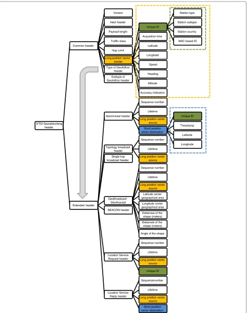
The ETSI technical specification TS 102 636-4-1 [4] stan-dardizes a non-IP approach to geographical addressing and forwarding. One of the focal points is the defini-tion of the appropriate packet headers. As illustrated in Figure 1, in total seven different headers are defined. Every header type begins with a common header, fol-lowed by an extended header which is different for every type. The header length varies between 36 and 88 bytes, dependent of the specific extended header. The header can contain geographical information about the network nodes. It is included in the long position vectors for source and sender, for which not only the coordinates but also speed, heading, and altitude are always given, together with information regarding acquisition time and accu-racy. The destination area in case of geo-casting can be specified using the GeoBroadcast/GeoAnycast extended header. The shape of area can be a circle, a rectangle, or an ellipse. Regarding the unique identification of the net-work nodes, the standard combines station type, station subtype, country, and a unique identification derived from the MAC address. The standard also describes mecha-nisms that allow all network nodes to maintain a local location table which contains information about other ITS stations in the neighborhood. This is especially useful in case of geo-unicast traffic. To support the communication of IPv6 packets over the VANET, the standard requires the GeoNetworking to IPv6 Adaption Sub-Layer (GN6ASL) which is discussed in the following subsection.
ETSI technical specification TS 102 636-6-1
To support the transmission of IPv6 packets over the ETSI GeoNetworking protocols described in the previous sub-section, the GeoNetworking to IPv6 Adaption Sub-Layer (GN6ASL) is proposed by ETSI in TS 102 636-6-1 [5]. It is an additional layer at the networking level that is posi-tioned between the GeoNetworking layer and the IPv6 networking layer. It integrates the functionalities of the IPv6 and GeoNetworking implementations in a transpar-ent way. This means that from the IPv6 point of view, GN6ASL is just a link-layer protocol which is responsi-ble for the communication of an IPv6 packet between two IPv6 nodes connected to the same link. From the GeoNet-working point of view, GN6ASL is just a higher layer that produces data packets that have to be geo-unicasted or geo-broadcasted to a specific destination. No adapta-tions to any of the two implementaadapta-tions are required, both protocols are not even aware of each others existence.
The main concept behind GN6ASL is the virtual link. A virtual link can span multiple physical links. Two types are
defined. A geographical virtual link (GVL) is a multicast-capable virtual link with geographically scoped bound-aries. It is associated with one single GeoNetworking GeoBroadcast/GeoAnycast area (also called geoarea). A topological virtual link (TVL) is a non-broadcast multi-access virtual link with topologically scoped boundaries. IPv6 multicast traffic may not be exchanged through a TVL. Both types of virtual links are associated to physi-cal interfaces in a slightly different manner: one physiphysi-cal interface can be associated to multiple GVLs but to only one TVL. The GN6ASL layer provides the virtual inter-faces to IPv6 in the form of virtual network interinter-faces. Such virtual interfaces can be assigned to either GVLs or TVLs, but a single virtual interface can only be associated to one GVL or one TVL.
To configure the virtual links and the IPv6 network on top of them, standard IPv6 stateless address autoconfigu-ration (SLAAC) is applied. IPv6 routers broadcast Router Advertisements on their configured GVLs using the corre-sponding virtual interfaces. This is translated by GN6ASL to geo-broadcast ETSI GeoNetworking packets with a destination area equal to the corresponding GVL area. Upon the reception of such an advertisement by other nodes within that area, these nodes will check if they have already configured this GVL. If not, they will create it using the destination area of the GeoBroadcast packet, configure a new corresponding virtual interface, and for-ward the packet over that interface to the IPv6 layer for further SLAAC execution. This approach is most suit-able in the situation where roadside units (RSUs) provide wireless coverage. In that case, each consecutive RSU is responsible for its own area, and will continuously broad-cast Router Advertisements on the corresponding GVL. Vehicles will then continuously join and leave GVLs based on their current position. The overhead on the wireless medium is limited to the broadcasts of the RSUs. How-ever, on roads where no such RSU coverage is available, vehicles are themselves responsible for creating GVLs that enable them to communicate with the surrounding vehi-cles. If all vehicles start defining a GVL around its own position, and hence continuously broadcast router adver-tisements, this will result in a significant load on the wireless medium. However, if too few nodes try to set up a GVL, this could lead to situations where vehicles are within each others’ communication range but fail to actu-ally communicate IPv6 packets. A suitable protocol that takes these trade-offs into account is required, but not yet available.
ETSI Geonetworking header
Common header
Version
Next header
Payload length
Traffic class
Hop Limit
Long position vector sender
Unique ID
Station type
Station subtype
Station country
MAC based ID Acquisition time
Latitude
Longitude
Speed
Heading
Altitude
Accuracy indicators Type of GeoAdhoc
header
Subtype of GeoAdhoc header
Extended header
GeoUnicast header
Sequence number
Lifetime
Long position vector source
Short position vector destination
Unique ID
Timestamp
Latitude
Longitude Topology broadcast
header
Sequence number
Lifetime
Long position vector source Single hop
broadcast header
GeoBroadcast/ GeoAnycast
Sequence number
Lifetime
Long position vector source
Latitude center geographical area
Longitude center geographical area
Distancea of the shape (meters)
Distanceb of the shape (meters)
Angle of the shape BEACON header
Location Service Request header
Sequence number
Lifetime
Long position vector source
Unique ID
Location Service Reply header
Sequencenumber
Lifetime
Long position vector source
Short position vector destination
will be encapsulated in a GeoNetworking packet. In case of a multicast IPv6 packet, this will be a GeoBroadcast packet with a destination area equal to the GVL area that corresponds with the virtual interface that received the packet. In case of unicast traffic, this will be a GeoUni-cast packet for which the destination address is directly derived from the interface identifier (IID, last 64 bits of the IPv6 address) of the destination IPv6 address. This kind of address resolution without neighbor discovery is possible because the TS 102 636-6-1 standard states that a compliant ITS station should use IPv6 addresses con-taining IIDs that directly resolve to its GeoNetworking address. Quite similar is the processing by GN6ASL of received GeoNetworking packets transporting IPv6 pack-ets (inbound traffic). The main challenge there is the determination of the virtual link that the packet belongs to. In case of GeoBroadcast messages, a GVL is searched for which the GVL area matches the destination area of the GeoBroadcast packet. In case of a GeoUnicast header, a slightly more complex procedure takes link scope and the relation between the position of the source and the available GVLs into account.
Communication requirements Application requirements
An enumeration of common cooperative ITS applications is given by different standardization organizations such as the C2C-CC and ETSI [34,35]. An analysis of their different requirements regarding supported networking techniques can result in a common list of requirements imposed on any generic VANET networking solution.
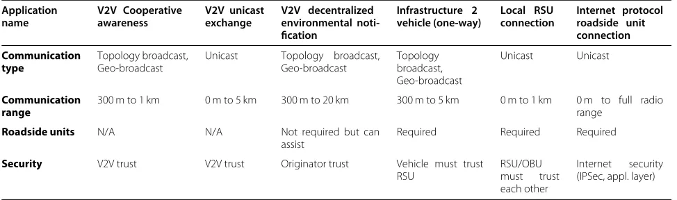
The C2C-CC investigated a large number of use cases. Based on that analysis, the consortium was able to define six generic applications that together can support all use cases. “Vehicle-2-Vehicle Cooperative Awareness” sup-ports the requirement for applications to share infor-mation with each other without any persistent com-munication link between the vehicles [36]. The corre-sponding messages are called Cooperative Awareness Messages (CAM). “Vehicle-2-Vehicle Unicast Exchange”
enables a communication link between two vehicles for the exchange of information. “Vehicle-2-Vehicle Decen-tralized Environmental Notification” provides informa-tion about events and roadway characteristics that are probably interesting to drivers for a certain time in a certain area [37]. The corresponding messages are called Decentralized Environment Notification Messages (DENM). “Infrastructure-2-Vehicle (One-Way)” supports the communication from RSUs to vehicles without a per-sistent communication link between vehicles and RSUs. “Local RSU connection” supports use cases where data between a vehicle and a RSU need to be sent from the vehicle to the RSU or bi-directionally. The last application, “Internet Protocol Roadside Unit Connection”, supports services that are offered to the driver by servers located in the Internet. A technical analysis of all six applications, containing among others the required communication techniques, is described in the C2C-CC Manifesto [34]. An overview is given in Table 1. The results are in line with the results obtained in the ETSI application analy-sis which deduced seven basic applications from a larger set of use cases. From Table 1, it can be concluded that from an application point of view, a VANET should sup-port some form of unicasting (IP- or geographical-based), topology broadcasting and geo-broadcasting.
Design requirements
The European ITS Communication Architecture des-cribed in the COMeSafety project [38] defined the ITS station as the core component in the four different instan-tiations (vehicle, personal, roadside, and central station). ITS Vehicle Stations and ITS Roadside Stations consist of a Communication & Control Unit (CCU) and one or more Application Units (AU). The CCU shall be equipped with at least a single ITS external communication inter-face to provide connectivity to external networks. This will typically be a short-range wireless network inter-face for VANET communication, often accompanied by a mobile data network interface for continuous Internet connectivity. Both the CCU and the AUs are also equipped
Table 1 General capabilities for C2C-CC applications
Application
Roadside units N/A N/A Not required but can
assist
Required Required Required
Security V2V trust V2V trust Originator trust Vehicle must trust
with an ITS internal communication interface for data exchange between the different ITS Station components, typically an Ethernet interface. Important communication requirements for this architecture are given in [39]:
• It must remain as close to the IP standard as possible, no strong modifications to the IP stack of the involved components should be required. • Because of radio throughput limitations, the
introduced overhead should be kept as low as possible.
• No modifications should be required in the AUs, since these can be IP standard legacy devices.
Solution description
In the previous sections an overview of possible VANET networking approaches was given. Based on an analy-sis of cooperative applications it was determined which of the networking techniques have to be supported by all VANET solutions. These requirements were supple-mented with requirements imposed by the European ITS Communication Architecture. Based on this set of requirements, the VANET networking solution presented in this article was designed.
In the “Application requirements” section, it was deter-mined that unicasting, topology broadcasting, and geo-broadcasting should be supported. However, no require-ments are imposed on the unicast technique: as long as it is possible to address and route data from a source to one well-defined destination, it does not matter if this des-tination is defined on an IP basis, or on a geographical basis. Combined solutions based on packet encapsulation (section “Combined solutions”) support both, but intro-duce a complexity in the routing process that could be avoided. If a networking solution would choose to only support IPv6 unicasting, and not geographical unicasting, it would still fulfill the communication requirements, but it would not need to support the more complex tunneling. Another advantage is that the position service for geo-graphical unicasting is not required in IP unicasting. In a similar manner, support for geo-anycasting can also be omitted without violating the application requirements, since only geo-broadcasting is demanded.
Based on these observations, the VANET networking solution presented in this article is designed as a pure IPv6 solution. This way, unicasting implementation is straightforward, and topology broadcasting can easily be supported by combining multicasting with correct usage of the Hop Limit header field. Geo-broadcasting however requires further refinement of the proposed solution. A mechanism is required to incorporate all required geo-graphical data in the standard IPv6 header. In the fol-lowing subsections our VANET networking solution is described in more detail.
Automatic address assignment
The main idea behind the chosen approach for automatic address assignment is the fact that the CCU receives a valid IPv6 address block from its operator or ISP (if the CCU has no mobile Internet uplink, this is performed once in a special configuration session at home, in the garage, etc.), divides this in smaller subnets, dedicates a subnet to every attached network (VANET, Internet uplink, internal station network, etc.) and correctly con-figures its own interfaces. Once these steps are performed, it starts broadcasting IPv6 router advertisements on its local network interfaces, just like any other IPv6 router would, enabling IPv6 SLAAC for all connected AUs [40].
The IETF recommends that mobile networks such as vehicles or mobile phones with an additional network interface (such as Bluetooth or 802.11) should receive a static/64 prefix to allow the connection of multiple devices through one subnet [41]. However, this range is too small for modern vehicular networks where the CCU is a mobile router interconnecting multiple sub-networks over its different network interfaces. Since the IPv6 Addressing Architecture defines that all global uni-cast addresses other than those that start with binary 000 have a 64-bit IID field [42], the CCU cannot divide the received prefix in smaller subnets. Therefore, we propose that the CCU should follow the general case described in [41], and receive a /48 prefix. This way, the CCU can construct the global unicast address: the first 48 bits con-tain the received static prefix, the next 16 bits define the subnets for the different connected networks, and the last 64 bits are the IID which is constructed using standard stateless configuration mechanisms.
This simple approach needs no adjustments to the AUs. The addresses used for the VANET networking interface of the CCU are dependent on the static prefix assigned to the CCU, therefore guaranteed to be unique. This means that there is no need to support the Neighbor Discov-ery protocol within the VANET, which would require more complex techniques to be supported in the VANET domain [6]. The only partial functionality of the Neighbor Discovery protocol that our solution does require on the VANET is address resolution to translates the next hop IPv6 address to the corresponding 802.11p MAC address. However, in an IPv6 ad hoc network, the next hop during multi-hop forwarding (which is determined by an active VANET routing protocol) will always be a node within communication range of the sender. This means that the neighbor solicitation and advertisement messages can be limited to single-hop broadcasts, which can directly be translated to MAC broadcast messages.
IPv6 geographical addressing scheme
requirement for many cooperative applications, a mecha-nism that incorporates the necessary geographical data is indispensable. To define this mechanism, a more profound insight in the required geographical data is required. Kovacs [31] defines a position vector containing the fol-lowing data fields: MAC id, C2C NET ID, timestamp, position in latitude, longitude and altitude, and speed and heading. Similar data fields are defined in the long posi-tion vector defined in [4] (see “Comparison with ETSI technical specification TS 102 636-4-1” section). Since this article chooses to work with IPv6 only, the MAC id and C2C NET ID can be dispensed. Position in lati-tude and longilati-tude is absolutely required for geocasting. A timestamp allows delay tolerant nodes to destroy queued packets or to keep valid messages alive in the geograph-ical destination area, without being aware of the applied upper layer protocols. Heading information can be used to limit rebroadcasting to certain areas, which could be a valuable mechanism to tackle the broadcast storm prob-lem in dense networking conditions. Speed and altitude are considered by the authors of this article as less deci-sive parameters for the addressing of nodes in a VANET context, and will not be included in the proposed solution. This decision is motivated by the observation that the applications analyzed in the “Application requirements” section rarely include speed or altitude information when defining the destination for their messages. Hence, it makes no sense to incorporate these concepts on the networking level. In the exceptional case that such func-tionality would be required, a more suitable approach is to apply a filter mechanism on the application layer that takes speed and/or altitude into account.
Different techniques to include this geographical infor-mation in VANETs are introduced by Gordillo [39] and Khaled [43]. Besides the tunneling approach that we wish to avoid in this article, they proposed two other solutions. The first approach is to include it in the application layer, e.g., using an extended DNS that is capable of storing geo-graphic information. This could easily be implemented, but it is not really adapted to a mobile environment, and the scalability of this approach is unclear. The second approach is to include all information in the IPv6 protocol. This can be done in three different ways: all information can be put in the IPv6 destination address using a spe-cial addressing scheme, it can be put in the existing IPv6 header fields by redefining their interpretation, or it can be encoded in a newly defined IPv6 Extension Header.
Applying a new IPv6 Extension Header allows a com-prehensible integration of the required geographical data into the IPv6 packets. However, the downside is that is causes additional overhead on top of the 40 bytes standard IPv6 header. Since one of the design requirements is that overhead should be kept as low as possible, it is preferred to define an addressing scheme that can incorporate all required geographical data in the standard IPv6 header. A suitable addressing scheme is depicted in Table 2. It has some similarities with the format of the IPv6 multi-cast address for a circular area presented in [44]. However, the approach presented in Table 2 uses another technique to encode area coordinates, and it omits the group ID of [44] in favor of the introduction of two headings to define the broadcasting zone within the circular area, and a timestamp to support delay tolerant networking.
As in all IPv6 addresses, the first 8 bits define the address type [42]. For geo-broadcasting we will use multicast packets, hence the value of these bits should be 0xFF. The next 4 bits, the flags, indicate various properties: if an address of a multicast rendezvous point is embed-ded in the multicast address, if the multicast address is assigned based on the network prefix, and if the mul-ticast address is permanently assigned by the IANA. In our case, the response to those three statements is nega-tive, therefore the appropriate value for this field is 0×1. The next 4 bits define the scope. Since this addressing scheme will be used to address other nodes within the VANET, none of the available assigned values such as link-local, site-local, or global seems entirely appropri-ate. It was chosen to use one of the unassigned scope values, since these are defined as available for adminis-trators to define additional multicast regions [42]. In our solution, a scope value of 0×6 indicates VANET (geo-or topology) broadcast. The next 32 bits contain the lati-tude of the center of the geocast area as a signed integer of 32 bits, represented in micro-degrees. The following 32 bits contain the longitude. The next 16 bits represent an unsigned integer that defines the radius of the circu-lar communication area in meters. This allows ranges up to 65 km. The following 4 bits contain Heading 1. It is an unsigned integer, leading to 16 possible values. There-fore, the actual heading value of the GPS receiver should be mapped to the closest fixed heading as depicted in Figure 2. Together with Heading 2 (the next 4 bits), the broadcast area is defined as the section between the cir-cular area and the zone between headings 1 and 2 in
Table 2 Geographical IPv6 addressing scheme
8 bits 4 bits 4 bits 32 bits 32 bits 16 bits 4 bits 4 bits 24 bits
Multicast Flags Scope Latitude Longitude Radius Heading 1 Heading 2 Expiration time
Figure 2Headings concept.
a counterclockwise direction. Circular geo-broadcasting can be achieved by putting the 0×0 value in both heading fields.
The last 24 bits are used as an expiration timestamp. They represent the least significant bits of the correspond-ing Unix time, a 32-bit value defincorrespond-ing the number of sec-onds elapsed since midnight of January 1, 1970. To handle buffer overflows introduced by this reduction in bitsize (where the value of a timestamp in the future can become smaller than the current time), we define the maximum supported difference between current time and expira-tion time as half of the interval, or 223s. Nodes will only consider a packet as expired when both of the following requirements are met (all time values are in the 24 bits for-mat): the current system time is equal to or higher than the packet expiration timestamp and the absolute difference between the current time and the expiration timestamp is lower than the maximum supported difference. This way, timestamp overflow will not result in the unnecessary expiration of the packet. Hence, our solution supports a packet validity of up to 97 days, with a granularity of 1 s. To allow geo-broadcasting without limitations in the time domain, 0×0 is defined as a special value for the packet expiration timestamp field.
Interpretation of IPv6 header parameters
The proposed addressing scheme allows to define receiver nodes in both place and time. In practical
implementations, additional information will be required. This is added to the standard IPv6 header by reinterpret-ing some existreinterpret-ing IPv6 header fields, as illustrated in Table 3. A notion of packet ID, not available in the standard IPv6 header, can assist flooding mechanisms to avoid double retransmission of the same packet. Such an ID is stored in the Flow Label field of the IPv6 header. The triplet source address, destination address, and flow label is then used to identify a unique packet. For every new VANET packet created on a host, the used Flow Label value has to be increased with 1. If applications on a host would be responsible for defining the value of the Flow Label field themselves, it is possible that they would be using the same values at the same time. If these different messages are sent to the same destination (e.g., topology broadcast), they will be considered as equal by the other nodes of the VANET. This way, new messages could wrongfully be discarded. Therefore, the configuration of the Flow Label field has to be coordinated by a global service on the host. To support topology broadcasts, correct values need to be used in the Hop Limit field in combination with a spe-cial destination address equal to FF16::1. The traffic class value is used to signal the IEEE 802.11p (or ITS-G5A) MAC layer which priority to be used. The source of any (geo-)broadcast packet always has to be the global uni-cast IPv6 address of the sender, since multiuni-cast addresses may not be used as source addresses [42]. This also allows unicast communication with nodes that were discovered through (geo-)broadcast announcement.
Table 3 Interpretation of IPv6 header parameters
4 bits 8 bits 20 bits 16 bits 8 bits 8 bits 128 bits 128 bits
Version Traffic class Flow label Payload length Next header Hop limit Source address Destination address
0x6 QoS class
802.11p
Packet ID Topology
broadcast: # hops
Global VANET unicast address
Table 4 Addressing scheme for intra-station multicasting of VANET packets (based on RFC 4489)
8 bits 4 bits 4 bits 8 bits 8 bits 64 bits 32 bits
Multicast Flags Scope Reserved Plen IID Group ID
0xFF 0x3 0x2 0x00 0xFF IID of CCU interface on intra-station subnet 0x0000FF16
Routing methodology
The presented VANET solution requires no changes on the AUs IP stack. Applications can translate their com-munication needs to specific destination addresses and header values, and create the correct packets to forward to the CCU. To send this data, it is only required that the AU routing table contains an entry indicating that the gateway for packets in the FF16::/16 domain is the CCU. To receive certain data, standard multicast groups cannot be applied over the VANET, since the used addresses do not correspond to predefined geographical zones. Hence, the applications cannot determine multicast group IDs to join. To solve this problem, one specific link-local mul-ticast group is defined within the ITS station on every connected subnet. The CCU will multicast a copy of every received VANET packet to these intra-station groups. The address of a group is determined using the method described in RFC 4489 [45]. As depicted in Table 4, the address will start with FF32:00FF, followed by the inter-face ID of the CCU intra-station interinter-face connected to that subnet. The last 32 bits can be chosen by the host, we define the value 0x0000FF16 to indicate this special multicast service. Its configuration is straightforward: the CCU provides standard multicast management functions
according to the specified addressing scheme on all con-nected subnets. Application units interested in receiving VANET traffic derive the appropriate multicast address from the IID of their default gateway (which is the CCU interface on their local network). To join this group they can rely on their standard multicast capabilities.
The CCU routing functionality requires some adjust-ments on the IP stack. It has to interpret the used geocast destination addresses, and has to know how to forward them on the VANET. The other way around, it has to be able to decide if it’s within the broadcast range of a geo-cast message received on the VANET interface, and to duplicate and forward it to the appropriate intra-station multicast groups. To decide when and how to rebroadcast or route messages, it can apply any desired broadcasting or ad hoc networking protocol. This flexibility is an impor-tant advantage of the proposed solution. It facilitates the fast adoption of novel VANET protocols which are regu-larly published in academic literature. Such protocols can be both VANET (geo)broadcasting schemes and IP-based networking protocols which are specifically optimized for the context of VANETs.
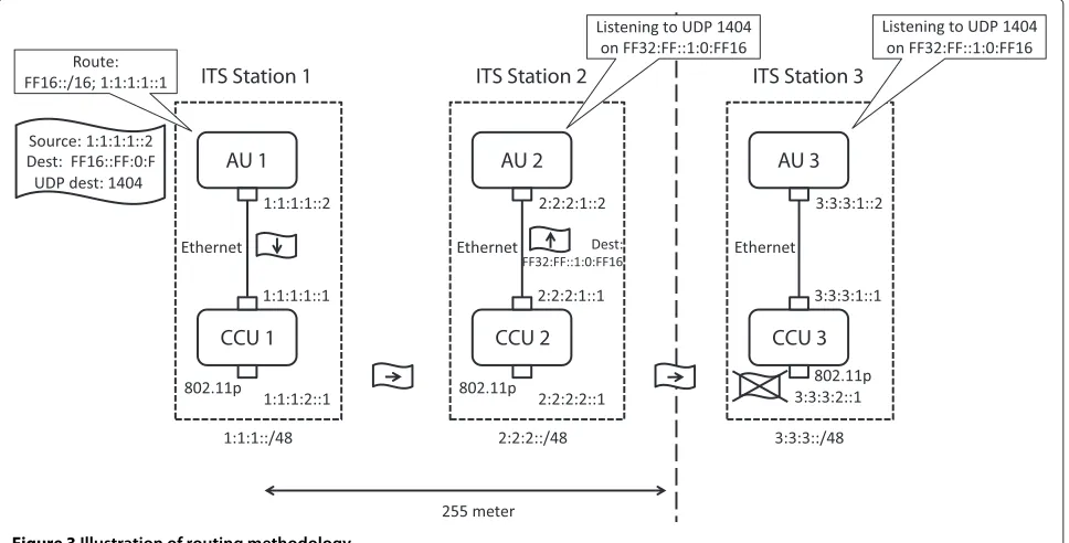
This routing methodology is illustrated in Figure 3. In this example, the CCU of every ITS station received a
static /48 prefix. As described in the “Automatic address assignment” section, this prefix is divided in several sub-domains (here LAN and VANET) using the next 16 bits, and IPv6 SLAAC ensures the correct configuration of the AU units connected to the CCU. To maintain clarity in this example, the IID part of the addresses is simplified. The VANET routing protocol implemented on the CCU is simple flooding. A cooperative safety application is active on all AU nodes, in this example it uses the UDP port 1404 to exchange messages. To receive VANET packets, the application listens to this UDP port on the appropriate intra-station multicast group. The routing table of every AU describes its CCU as the next hop destinations in the FF16::/16 domain.
The example starts when the cooperative safety appli-cation running on the AU of ITS Station 1 generates a warning that has to be geographically broadcasted. It creates an UDP/IPv6 packet with its own IPv6 global uni-cast address (1:1:1:1::2) as source address. The destination address is constructed using the scheme presented in the “IPv6 geographical addressing scheme” section. To keep this example clear, the location of ITS Station 1 is defined as 0 degrees latitude and 0 degrees longitude. It is chosen to define a circular communication area (hence headings 1 and 2 are both 0×0), with a radius of 255 m (0xFF). The expiration time is 15 s (0xF). Hence, the destination address is FF16::FF:0:F. The UDP destination port of the packet is 1404. When this packet is transferred to the (standard) routing layer of the AU, it looks up the gateway for that packet, which is CCU 1, and forwards it to that CCU over the Ethernet interface. When CCU 1 receives this packet, its modified IPv6 routing layer recognizes this packet as a geo-broadcast IPv6 packet, and broadcasts it on the VANET 802.11p interface. This broadcasted packet is received by the CCU of ITS Station 2, which again rec-ognizes it as a geo-broadcast packet. Based on its own location, it determines that it is positioned within the destination communication area. The CCU 2 network-ing stack multicasts a copy of the packet to every subnet within the ITS station. In this case, this is the Ether-net LAN. In the example, we use simplified IIDs, for the CCU 2 LAN interface this is ::1. Therefore, the multicast address for disseminating VANET packets on this LAN is FF32:FF::1:0:FF16. After delivery of a copy to all sub-nets, the packet is given to the VANET routing protocol for further relaying. The simple flooding of this exam-ple decides to rebroadcast the original packet through its VANET interface. This packet is then received by CCU 3. Based on its location, this CCU decides that it is outside of the destination area, and destroys the packet.
The above example focused on the geo-broadcasting aspect of the proposed VANET solution. However, sup-port for the other required communication modes is quite similar. If AU 1 would have chosen to disseminate the
message using topology broadcasting with a hop limit of 3, the difference would be that the destination address of the generated packet becomes FF16::1, as described in the “Interpretation of IPv6 header parameters ’’ section. Then the packet is be given to CCU 1, which reduces the hop limit value with 1 (new value = 2) and then broadcasts it on the VANET interface. CCU 2 receives this packet, but per-forms no geographical filtering, it reduces the hop limit (new value = 1), forwards a copy to AU 2 and rebroadcasts the original on its VANET interface. This packet is then received by CCU 3, which will destroy the packet because any relay action by CCU 3 results in the value of hop limit becoming 0. In case of unicast traffic, the destination address of the packet becomes the global unicast address of the receiver. To support this form of communication, it is required that a unicast VANET ad hoc networking pro-tocol is active on every CCU. This way, routes between the different CCUs are maintained. In the routing table of every AU, its CCU is configured as default gateway. This way, the created unicast packet will be forwarded by the (standard) routing layer of the AU to the CCU, which hands it over to the unicast ad hoc protocol which can deliver the packet of the VANET to the CCU which cor-responds with the destination AU. This CCU will then forward the packet to the destination AU.
Implementation details
The approach to VANET networking presented in the previous sections was validated with an actual implemen-tation. Two frameworks were applied: the Click Modular Router was used to implemented the networking stack, while the applications were developed in Java. The imple-mentation of both the networking layer and the demon-strator applications could be performed within limited manpower constraints, while providing all required func-tionality. This illustrates the benefits of reducing the level of complexity in VANET design. In the next subsections, more details are given regarding both aspects of the imple-mentation.
Networking layer
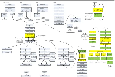
Figure 4Click modular router configuration of the implemented networking stack.Light grey elements correspond with a standard IPv6 router, yellow elements are additional VANET elements which are part of the click standard library, green elements were specifically developed for the VANET networking stack.
elements in light grey are the elements included in a stan-dard IPv6 router. The yellow elements are elements which are part of the Click standard library but where inserted in the configuration to implement our VANET solution. The green elements are novel elements that were specifi-cally implemented in the context of this VANET research. Hence, in the entire figure, only the green elements had to be programmed to obtain a full implementation of our solution.
The starting point of our implementation was the con-figuration corresponding with a standard IPv6 router. As mentioned, all required elements and the corresponding configuration are part of the Click standard library. In our specific case, the router is connected to the Linux stack of the host, and three network interfaces: an intra-station Ethernet LAN and Wi-Fi WLAN, and the VANET IEEE 802.11p interface. To provide maximum control of all VANET transmission aspects, the VANET interface (which relies on the Madwifi wireless driver) was config-ured in a special mode called “monitor mode”. This mode requires the presence of some additional elements to per-form error checks normally executed in the driver itself.
Examples are the FilterPhyErr, FilterTx, and WifeDupe-Filter elements.
Two adjustments were then made to the standard IPv6 router configuration. First of all, on the outgoing VANET interface, packets are classified according to their anno-tated QoS class and put in different queues. A priority scheduler is placed after them. As a result, every time that the VANET interface is ready to transmit a new packet, packets with the highest priority will be selected for trans-mission first. Only if the queue corresponding with the highest QoS class is empty, packets will be retrieved from the second highest QoS class queue. Only if that queue is also empty, packets can be retrieved from the third highest QoS class queue, and so on. The second adjustment was the introduction of a classifier in the forwarding chain of the router. If messages in the FF16::/16 domain pass this classifier, they do not flow into the standard lookup table of the router, but to the part on the right of the figure which provides all geo-networking functionality.
also requests the current node location at the position info manager (an element that periodically polls the Linux dae-mon GPSD to retrieve the current position and GPS time). If the processed packet is a topology broadcast packet, it will forward it to the next element. If it is a geo-broadcast packet, it will checked if the current position of the node is part of the destination area. If so, the packet is passed to the next element, otherwise the packet is destroyed. The DTN dropper is the next element in the chain. It has a similar function as the Geo dropper element, but it focuses on time instead of location. It destroys expired geo-broadcast packets and forwards the other packets to the next element. This next element is a filter (based on the usage of a dedicated UDP port) for control messages of the Simplified Wireless Routing Protocol (SWRP). This protocol is a simplified version of the wireless routing pro-tocol [47]. It is a pro-active ad hoc routing propro-tocol that exchanges routing tables between one-hop neighbors. It uses the topology broadcast address FF16::1 together with a hop limit of 1 to disseminate the routing table of a node to its peers. The SWRP element provides the core functionality of the protocol, it relies on other elements placed before and after it to add and remove network and transport headers and to assign highest priority to its messages.
Geo-networking packets not destined for the SWRP element are passed to the DecIP6HLIM element, which reduces the value in the IPv6 Hop Limit field by one. In contradiction to the similar element in the standard IPv6 section of the Click configuration, there is no con-nection to an element that sends ICMP6 error messages to the source network interface. On the VANET, such functionality would cause unnecessary capacity waste. The next element in the forwarding chain is the Sim-ple flooder element. It maintains a list of all packets that it recently forwarded. As described in the “Interpreta-tion of IPv6 header parameters” sec“Interpreta-tion, the triplet source address, destination address, and flow label are used to uniquely identify each packet. If the Simple flooder ele-ment receives a packet that is already included in its list, then the packet is destroyed. Else the corresponding ID is added to the list, and the packet is passed to the next ele-ment: the Multicast Tee. This element does nothing more then duplicating a message received on its input to all its outputs. This means that a copy of the geo-networking packet is forwarded to the Linux networking stack of the host, the intra-station LAN and WLAN, and the VANET interface. The check paint elements on the outgoing con-nections of the Multicast Tee make sure that the packet is not forwarded to the router input from which it orig-inated (host, LAN, or WLAN). On the VANET interface such an inspection is not foreseen since in this context message relaying requires that packets can be forwarded on the same network interface as the one that they were
received on. Before the packets are put in the outgoing queue of each network interface, the appropriate MAC headers are placed in front of the IPv6 geo-networking packet. This is carried out by the different multicast ele-ments. In case of intra-station multicasting, the applied addresses correspond with the scheme described in the “Routing methodology” section. In case of VANET traf-fic, the destination MAC address always is the broadcast address FF:FF:FF:FF:FF:FF. On the VANET, a last check is also performed before handing the packet over to the VANET interface. The value of the Flow Label field is inspected, if no value has been set and the packet origi-nated from this ITS station, the field is updated with the appropriate value.
Application layer
The implementation of the networking layer was demon-strated on public roads with different common cooper-ative ITS applications: road works warning, emergency vehicle warning, bicycle collision alert, and broken down vehicle warning. For the interested reader, video footage of this demonstration can be found on YouTube [48]. In the first application, a message was continuously broad-casted by a RSU which was temporary installed at a road works site. The onboard unit (OBU) of the demo vehi-cles received these messages and warned the driver when the hazardous location was approached. The emergency vehicle warning was an example of V2V communication, allowing the driver of the emergency vehicle to electroni-cally notify the surrounding vehicles to give way. The bicy-cle collision alert demonstrated the value of ad hoc com-munication between vehicles and vulnerable road users. In case of limited visibility at a junction, the cooperative application warned the driver in case of a collision course with the bicycle. A similar use case was demonstrated with the last application: broken down vehicle warning. In this case the goal was again to inform the driver about hazards in case of limited visibility, but the communication pattern was V2V instead of vehicle-to-bicycle.
//In this example, all required variables to define the communication behavior are
//command line arguments String myVanetAddress=args[0];
String destinationVanetAddress=args[1]; //unicast, FF16::1 or determined by the library
int toPort=Integer.parseInt(args[2]); int trafficClass=Integer.parseInt(args[3]); int hopLimit=Integer.parseInt(args[4]);
//create the socket
InetSocketAddress myAddress = new InetSocketAddress (myVanetAddress,0);
MulticastSocket senderSocket = new MulticastSocket (myAddress);
senderSocket.setTrafficClass(trafficClass); senderSocket.setTimeToLive(hopLimit);
//create the message
testMessage = new TestMessage(); //dummy object, implements the interface Serializable
ByteArrayOutputStream bos = new ByteArrayOutput-Stream();
ObjectOutputStream oos = new ObjectOutputStream (bos);
oos.writeObject(testMessage);
//send the message
InetAddress toAddress = InetAddress.getByName (destinationVanetAddress);
DatagramPacket msg =
new DatagramPacket(bos.toByteArray(), bos. toByteArray().length, toAddress, toPort);
senderSocket.send(msg);
Evaluation
The main goal of the VANET networking solution pre-sented in this article is to fulfill all imposed requirements in a simple yet effective manner. In this section, it is evaluated to which degree this goal has been achieved.
In the “Communication requirements” section it was concluded that a VANET should support some form of unicasting, topology broadcasting, and geo-broadcasting. Since our solution supports IPv6 unicast, IPv6 topology broadcasting, and geo-broadcast using the standard IPv6 header, this indeed is the case. Another requirement was that the proposed solution should remain as close as pos-sible to the IP stack, should limit the overhead and should not require modifications to the AUs. These requirements are also fulfilled. So, in theory, the solution presented in this article fulfills all imposed requirements. To jus-tify this conclusion, an experiment was performed on the IBBT w-iLab.t wireless testbed. This experiment is pre-sented in the “Experimental validation of the provided functionality” section.
Assuming that the support of all required function-ality has been experimentally proven, it is still unclear how our solution holds up against the alternative VANET techniques introduced in the “VANET networking tech niques” section. In almost all available publications pro-cessed in the corresponding literature study, no informa-tion was given about the practical details regarding the applied network header format, addressing scheme, and so on. In general, the publications focused on the defined routing or broadcasting schemes, assuming that a net-working stack (being IP based or geographical netnet-working based) is available to support their solutions. The main exceptions were all publications related to the GeoNet project. This project pioneered the domain of combined VANET solutions. During the course of the project, sev-eral publications focused on the different design and implementation issues, touching topics such as network headers, addressing schemes, and so on. No similar litera-ture could be found anywhere else.
Since the work of the GeoNet project (which was exe-cuted between 2008 and 2010) was continued in the recently released ETSI standards, it seemed most appro-priate to focus on these standards when evaluating our solution against the related state-of-the-art. Therefore, in the “Comparison with ETSI technical specification TS 102 636-4-1” and “Comparison with ETSI technical specifica-tion TS 102 636-6-1” secspecifica-tions our approach is compared with the corresponding ETSI standards for geographical networking and IPv6 encapsulation. To conclude the eval-uation of our solution, the “Complexity analysis” section will focus on the bigger picture, evaluating the reduction in complexity of our solution compared to the tunneling approach.
Figure 5Topology of the third floor of the IBBT w-iLab.t wireless testbed.On the figure the physical nodes are depicted. On each of these devices, two IEEE 802.11 a/b/g interfaces are available. For each of those interfaces an entirely independent VANET networking stack is deployed on the physical node. Hence every depicted node actually corresponds with 2 VANET nodes during the experiment.
different communication patterns: single-hop topology broadcasting of CAM messages by all nodes, multi-hop geo-broadcasting of DENM messages originating from six different nodes (ID 1–6), and IPv6 unicast VoIP com-munication between two other nodes (from nodes 99 to 101). Based on [49], a transmit power of 13 dBm was cho-sen for this experiment. As shown in the coding example found in the “Application layer” section, applications can select the different types of communication by configur-ing the appropriate destination address, hop limit, and traffic class. Table 5 summarizes the values applied in the experiment.
To capture end-to-end performance statistics such as delay and packet success rate (PSR), a testing applica-tion was created. This applicaapplica-tion can be configured to emulate data flows according to the desired application characteristics. Tunable parameters are the data size of the created messages, interval between two consecutive messages, number of messages to be created, and a range of message identification numbers for which the perfor-mance metrics should be recorded. The actual content of the communicated messages is random dummy data. In contradiction to our demo applications which were imple-mented in Java, this testing application was impleimple-mented within the Click Modular Router framework. This way, the same tests can be performed on actual hardware and in the NS-2 network simulator (see “Experimental compar ison with TS 102 636-4-1” section). To mimic CAM data
traffic, messages with 300 bytes of application data were sent every 100 ms. The same characteristics were applied to emulate DENM traffic. These parameter values corre-spond with the results of [49]. In the VoIP case, messages with a data size of 80 bytes were sent every 30 ms. This corresponds with the behavior of the iSAC codec which Skype uses by default [50]. The results of the experiment are depicted in Figures 6 and 7.
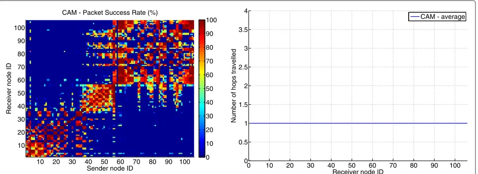
Figure 6 illustrates the reception of CAM messages. On the left part of the figure, every point corresponds with the tuple (sender node ID, receiver node ID). The color of the point indicates the percentage of CAM broadcast messages originating from the sender that were actually received by the receiver. It varies between blue (no com-munication possible) and red (perfect comcom-munication). On the diagonal the sender and receiver are the same. On this point the value corresponds with the number of messages that the node actually created during the exper-iment. This way it can easily be inspected if the request data load was generated during the experiment. If so, the entire diagonal should be dark red. It can be observed that for every sender node, the nodes that received the broad-casted CAM messages are situated around the diagonal. This corresponds with nodes that are in the vicinity of the sender. The diversity in the amount of receiver nodes per sender was nearly identical over several runs of the experiment, and can be explained by the fact that the w-iLab.t testbed is an indoor testbed. The nodes are spread
Table 5 Parameter values applied in the experimental functionality validation
Application Node ID Destination address Hop limit Traffic class
CAM 1–110 FF16::1 1 3
DENM 1 FF16:424C:2521:406F:11C8:002D:0000:0000 255 3
DENM 2 FF16:424C:2521:406F:11C8:002D:0000:0000 255 3
DENM 3 FF16:424C:250E:406F:11DC:002D:0000:0000 255 3
DENM 4 FF16:424C:250E:406F:11DC:002D:0000:0000 255 3
DENM 5 FF16:424C:2504:406F:11C8:002D:0000:0000 255 3
DENM 6 FF16:424C:2504:406F:11C8:002D:0000:0000 255 3
10 20 30 40 50 60 70 80 90 100
CAM - Packet Success Rate (%)
0
Figure 6Reception of CAM messages on the IBBT w-iLab.t testbed.The color of each point indicates the percentage of CAM broadcast messages originating from the sender that were actually received by the receiver.
around an entire floor of an office building. Due to the presence of obstacles with different propagation charac-teristics (wooden office partition walls, concrete elevator shaft, brick walls around kitchen, and toilets), communi-cation properties of links can vary greatly based on the specific location of sender and receiver node. To indi-cate that the CAM messages were limited to single-hop communication, the right part of Figure 6 depicts the aver-age number of hops traveled before a CAM messaver-age was received. As desired, the value is 1 for all nodes. From the above, it can be concluded that the topology broadcast functionality is provided by our solution.
The left part of Figure 7 illustrates the reception of the DENM and VOIP messages. TheX-axis corresponds with the receiver node ID, theY-axis with the PSR. Every series on the figure corresponds with a different sender node.
So one series on the figure illustrates to which degree the messages created by a single source could be received by all other nodes. To avoid overloading the figure, only half of the DENM sources are depicted. When focusing on the DENM results, it should be mentioned that the length of the testbed grid topology is about 90 m. The destina-tion address of the DENM applicadestina-tions where configured in such a way that they define a circular area around the position of the source node, with a radius of 45 m (see Table 5). The source nodes 1–6 are all located at one end of the topology, close to each other. The used Hop Limit value is 255, allowing for multi-hop dissemination of the messages. As can be seen from Figure 7, the desired communication characteristics are achieved: the DENM messages are only received by half of the nodes, corre-sponding with all nodes located within the geo-broadcast
0 10 20 30 40 50 60 70 80 90 100
destination area. To indicate that the DENM messages were in fact relayed by intermediate nodes, the right part of Figure 7 depicts the average number of hops traveled before a DENM message originating from node 1–6 was received. This value gradually increases from 1.2 to 3.4. When focusing on the VOIP results, again the desired behavior is observed on the left part of Figure 7: only node 101 received the unicast messages sent out by node 99.
Comparison with ETSI technical specification TS 102 636-4-1
The comparison of the proposed solution with the ETSI TS 102 636-4-1 standard was approached both from a theoretical and an experimental point of view. In the following subsections both aspects are presented.
Theoretical comparison with TS 102 636-4-1
The geonetworking techniques described in TS 102 636-4-1 are quite similar to those proposed in this article. The most important difference between both approaches
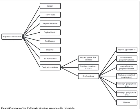
lies in the packet headers. As elaborated in the “ETSI technical specification TS 102 636-4-1” section, the ETSI standard defines seven different headers. This means that the networking layer has to implement seven different interpretations of the geonetworking header. In contradic-tion, as illustrated in Figure 8, the header format defined in this article is more straightforward. There is only a sin-gle header format, all information is always available at the same position in the header. During packet process-ing, the only point of attention is the interpretation of the destination address. If it is the special address FF16::1, it should be handled as a topology broadcast packet. If it is not this special address, but does start with 0xFF16, then it should be handled as a geo-broadcast packet according to the addressing scheme proposed in this article. Otherwise, the packet is handled as a standard IPv6 packet.
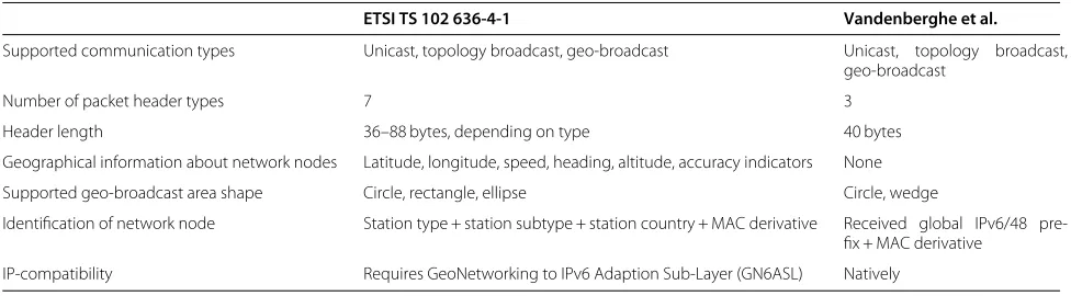
Other differences can also be observed. They are sum-marized in Table 6. The ETSI header contains geograph-ical information about the network nodes. This is not the case in the proposed solution, which only applies
Proposed IPv6 header
Version
Traffic class
Sequence number
Payload length
Next header
Hop limit
Source address
Destination address
Unicast: global IPv6 address
Topology broadcast: FF16::1
GeoBroadcast
Address type: 0xFF16
Latitude center geographical area
Longitude center geographical area
Radius geographical area (meters)
Heading 1 geographical area
Heading 2 geographical area
Lifetime
Table 6 Differences between ETSI TS 102 636-4-1 and the approach presented in this article
ETSI TS 102 636-4-1 Vandenberghe et al.
Supported communication types Unicast, topology broadcast, geo-broadcast Unicast, topology broadcast, geo-broadcast
Number of packet header types 7 3
Header length 36–88 bytes, depending on type 40 bytes
Geographical information about network nodes Latitude, longitude, speed, heading, altitude, accuracy indicators None
Supported geo-broadcast area shape Circle, rectangle, ellipse Circle, wedge
Identification of network node Station type + station subtype + station country + MAC derivative Received global IPv6/48 pre-fix + MAC derivative
IP-compatibility Requires GeoNetworking to IPv6 Adaption Sub-Layer (GN6ASL) Natively
geographical information to define destination areas for geo-broadcasting. However, the absence of this informa-tion does not lead to reduced funcinforma-tionality compared to the ETSI standard since both support the same commu-nication forms. These are unicast traffic between any two nodes in the network, topology broadcasting, and geo-graphical broadcasting. It is true that the ETSI standard produces a local location table which contains infor-mation about other ITS stations in the neighborhood, and that this information could be useful for higher-layer applications. However, keeping the aim for a KISS approach into account, the authors of this article are con-vinced that if this information is required by the higher layers, that it should be collected and maintained on those higher layers. This opinion is strengthened by the Internet design guidelines described in RFC 1958 [2] (Architec-tural Principles of the Internet) which not only recom-mends the KISS principle, but also literally states that modularity is good, and that if you can keep things sepa-rate, you should do so. The most feasible approach seems to assign the task of creating a local location table to a higher layer service on every ITS station which makes this information available to all other applications. This approach would be in line with the European ITS Commu-nication Architecture [38] which describes a facility layer between the networking layer and the application layer. One of the considered facilities is the support for a Local Dynamic Map, which corresponds with the creation of a local location table.
Another difference lies in the length of the header. In the ETSI solution, this varies between 36 and 88 bytes, while the IPv6 solution has a fixed header length of 40 bytes. Main reason for this difference lies in the fact that the ETSI header includes some more information than the IPv6-based proposition. Most of this informa-tion is included in the long posiinforma-tion vectors for source and sender (the source is defined as the node that originates a packet, the sender as the node that has sent the packet, which will be different from the source during multi-hop forwarding). For both nodes, not only the coordinates
but also speed, heading and altitude are always given, together with information regarding acquisition time and accuracy. In the proposed solution, no geographical infor-mation is given regarding source and sender nodes, since this is not required to provide all required communica-tion forms. Similar to the remark regarding the locacommunica-tion table, it can be stated that if an application needs to know location information regarding the source of a message, it is more convenient that the source application includes this information in the message payload. This approach is in line with the ETSI standards that describe message payload formats for cooperative applications (CAM [36] and DENM [37]). In both message types location infor-mation is included that describes the location of the event or source node. This information includes latitude and longitude, altitude, speed and heading.
This removal of redundant data leads to shorter header lengths, which is a valuable characteristic since VANETs can suffer from capacity problems under high vehicle densities [51,52]. If we consider that the majority of coop-erative ITS applications will rely on CAM and DENM messages to exchange information, it can be stated that the typical payload for a secure VANET packet will be 300 bytes [49]. When taking the different header lengths into account (40 bytes IPv6, 36–88 bytes ETSI), it can be concluded that in case of the shortest ETSI header the medium occupation time for every message in our pro-posed solution is 1% longer than in the ETSI approach. However, in case of the longest ETSI header, the medium occupation time for of the ETSI approach becomes 14% longer than in our proposed solution. To evaluate the impact of this increase, an experiment using our imple-mentation is presented in the “Experimental comparison with TS 102 636-4-1” section.