Hardware Manual
04.045. Data and SMDR
1. Installing Cabinets
3. Installing Extensions
and Trunks
4. Telephones and
Optional Equipment
2. PCB Installation and
Startup
6. LAN Connection
Technical Support Web Site:
http://ws1.necii.com (registration is required)
This manual has been developed by NEC Unified Solutions, Inc. It is intended for the use of its customers and service personnel, and should be read in its entirety before attempting to install or program the system. Any comments or suggestions for improving this manual would be appreciated. Forward your remarks to:
NEC Unified Solutions, Inc.
4 Forest Parkway Shelton, CT 06484
necunifiedsolutions.com
Nothing contained in this manual shall be deemed to be, and this manual does not constitute, a warranty of, or representation with respect to, any of the equipment covered. This manual is subject to change without notice and NEC Unified Solutions, Inc. has no obligation to provide any updates or corrections to this manual. Further, NEC Unified Solutions, Inc. also reserves the right, without prior notice, to make changes in equipment design or components as it deems appropriate. No representation is made that this manual is complete or accurate in all respects and NEC Unified Solutions, Inc. shall not be liable for any errors or omissions. In no event shall NEC Unified Solutions, Inc. be liable for any incidental or consequential damages in connection with the use of this manual. This document contains proprietary information that is protected by copyright. All rights are reserved. No part of this document may be photocopied or reproduced without prior written consent of NEC Unified Solutions, Inc.
Table of Contents
Aspire S Hardware Manual Table of Contents ◆ i
Table of Contents
Section 1:
Installing the Cabinet . . . 1-1
GENERAL PRECAUTIONS . . . 1-1 INSTALLING THE CABINET . . . 1-1 Unpacking. . . 1-1 Before Installing . . . 1-1 Site Requirements. . . 1-2 Environmental Requirements . . . 1-2 Removing the Front Cover (Figure 1-1). . . 1-2 Securing the Cabinet to the Floor (Figure 1-2 - Figure 1-4) . . . 1-4 Securing the Cabinet to the Wall (Figure 1-5 - Figure 1-8) . . . 1-7 Securing the Cabinet to a Rack (Figure 1-9 - Figure 1-12) . . . 1-10 INSTALLING THE PCBS . . . 1-14 PCB Installation (Figure 1-13 - Figure 1-16) . . . 1-14 GROUNDING THE CABINETS . . . 1-18 Connecting the System Ground (Figure 1-17) . . . 1-18 COMPLETING THE INSTALLATION . . . 1-20 Setting the Cable Pass-Through (Figure 1-18 - Figure 1-20). . . 1-20 Reinstalling the Front Cover (Figure 1-21 - Figure 1-22) . . . 1-22
Section 2:
PCB Installation and Startup . . . 2-1
Table of Contents
Table of Contents
Aspire S Hardware Manual Table of Contents ◆ iii
Section 3:
Installing Extensions and Trunks. . . 3-1
Table of Contents
Section 4:
Telephones and Optional Equipment. . . 4-1
Table of Contents
Aspire S Hardware Manual Table of Contents ◆ v
PSA-R Adapter (Figure 4-46 - Figure 4-47) . . . 4-47 Installing the PSA-R Adapter: . . . 4-47 Using the PSA-R Adapter:. . . 4-48 Speakerphone (HF-R) Adapter (Figure 4-39 - Figure 4-40) . . . 4-49 Installing the HF-R Adapter: . . . 4-49 VoIP Adapter (Figure 4-51 - Figure 4-53) . . . 4-51 Installing the VoIP Adapter: . . . 4-51 POWER FAILURE TELEPHONES. . . 4-53 Power Failure (Figure 4-54) . . . 4-53 Connector Pin-Outs on COIU PCB for Power Failure Circuits . . . 4-53 Installing the Power Failure Telephones: . . . 4-54 RELAYS . . . 4-56 Relays - External Page, Door Box, General Purpose (Figure 4-15, Figure 4-55) . 4-56
To connect a dry contact relay device to a Door Box/External
Page Relay: . . . 4-56 SLT ADAPTER. . . 4-58 Using the SLT Adapter (Figure 4-56 - Figure 4-58) . . . 4-58 Installing the SLT Adapter . . . 4-58 Wall-Mounting the SLT Adapter. . . 4-59 Telephones. . . 4-60 34-Button Super Display Telephone – P/Ns 0890049 & 0890050 . . . 4-60 34-Button Display Telephone — P/Ns 0890045 & 0890046. . . 4-61 22-Button Display Telephone — P/Ns 0890043 & 0890044. . . 4-61 22-Button Standard Telephone — P/Ns 0890041 & 0890042. . . 4-62 2-Button Telephone — P/Ns 0890047 & 0890048 . . . 4-62 Cordless Single Line Headset Telephone, CT-11 — P/N 730090 . . . 4-63 Cordless Telephone — P/N 730088/730087 . . . 4-64 IP Station Equipment. . . 4-73 34-Button Aspire IPhone - BK — P/N 0890065 . . . 4-73 H.323 IP Phone — P/N 780005 . . . 4-73 SUPER DISPLAY LCD . . . 4-76 Positioning the Super Display LCD (Figure 4-76, Figure 4-77) . . . 4-76 TELEPHONE LEGS . . . 4-77 Using the Telephone Legs (Figure 4-78 - Figure 4-82) . . . 4-77 Adjusting the Leg Height . . . 4-77 WALL-MOUNT BRACKET . . . 4-80 Using the Wall-Mount Bracket . . . 4-80 Installing the Wall-Mount Handset Bracket (Figure 4-83 - Figure 4-89) . . . 4-80 Removing the Phone From a Wall-Mounting Bracket
(Figure 4-90 - Figure 4-91) . . . 4-84 Installing the 2-Button Phone’s Wall-Mount Bracket
Table of Contents
Section 5:
Data and SMDR . . . 5-1
DATA OVERVIEW . . . 5-1 Data Communications . . . 5-1 APA Adapter . . . 5-1 APR Adapter . . . 5-1 CTA Adapter . . . 5-2 CTU Adapter . . . 5-2 Data Communication Availability With Hardware . . . 5-2 Ports for APR Adapter . . . 5-3 Programming for System and Alarm Reports . . . 5-3 SMDR . . . 5-4 Using SMDR (Figure 5-1) . . . 5-4 Installing SMDR . . . 5-4 Programming SMDR . . . 5-6
Section 6:
LAN Connection . . . 6-1
LAN DEVICES . . . 6-1 Using LANs . . . 6-1 PCBs: . . . 6-3 Terminals: . . . 6-3 Hardware: . . . 6-4 Installing a LAN Device or VoIP Telephone . . . 6-5
Section 7:
Specifications and Parts List. . . 7-1
Table of Contents
Aspire S Hardware Manual Table of Contents ◆ vii
Table of Contents
-Section 1: Installing the Cabinet
Aspire S Hardware Manual Section 1: Installing the Cabinet ◆ 1-1
1
Section 1:
Installing the Cabinet
Section 1: Installing the Cabinet
GENERAL PRECAUTIONS
● To avoid shock or equipment damage, do not plug in or turn the system power on before completing the installation process.
● Avoid working with the equipment during electrical storms.
● Use only commercial AC power to prevent shock or fire.
● Use the power cord supplied for the cabinet.
● Do not bundle AC power cords together to prevent the cords from overheating.
● Make sure the cabinet has a proper earth ground.
● Install batteries with the correct polarity to prevent damaging equipment.
● The cabinet should not be placed on unstable surfaces to avoid damage.
INSTALLING THE CABINET
Unpacking
Unpack the equipment and check it against your equipment lists. The cabinet contains a power supply installed by the manufacturer, however, no PCBS are installed. Inspect for physical damage. If you are not sure about a component’s function, review the information for the component within this manual. Contact your Sales Representative if you have additional questions.
Make sure you have appropriate tools for the job, including: a test set, a punch down tool, and a digital voltmeter.
Before Installing
Section 1: Installing the Cabinet
Site Requirements
The system can be floor-mounted (optional floor mounting brackets required), wall-mounted, or rack-mounted (rack mounting hardware required). Ensure that enough space is available around the cabinet to allow room to work with the cabinet for installation and maintenance.
The system requires a three-prong dedicated 110 VAC 60 Hz circuit (NEMA 5-15 receptacle) located within 6 feet of the AC receptacle. Telco should install the RJ21X to the right of the cabinet. Extension blocks should be installed to the left of the cabinet.
The cabinet is shipped fully assembled. The following is enclosed with the cabinet:
● 1 green 14AWG ground wire (installed to the power supply’s backplane)
● 1 black three-prong power cord (packed outside the cabinet)
Environmental Requirements
Meeting and maintaining established environmental standards maximizes the life of the system. Be sure that the site selected for the cabinet is not:
1. In direct sunlight or in hot, cold or humid places.
2. In dusty areas or in areas where sulfuric gases are produced. 3. In places where shocks or vibrations are frequent or strong.
4. In places where water or other fluids comes in contact with the main equipment. 5. In areas near high-frequency machines or electric welders.
6. Near computers, telexes, microwaves, air conditioners, TVs, wireless devices, medical instruments, etc. 7. Near radio antennas (including shortwave).
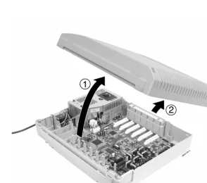
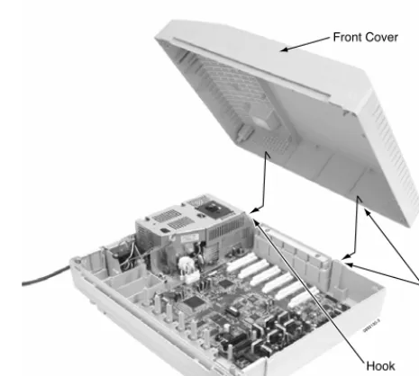
Removing the Front Cover
(Figure 1-1)
1. Position the cabinet on the floor near the MDF within 6 feet of the dedicated AC outlet. (Do not secure the cabinet to the wall at this time).
2. Loosen the four captive front panel retaining screws.
Section 1: Installing the Cabinet
Aspire S Hardware Manual Section 1: Installing the Cabinet ◆ 1-3
1
Figure 1-1: REMOVING THE FRONT COVER Step 1
Step 2
0893130-1
screws
screws Front Cover
0893130-2
1
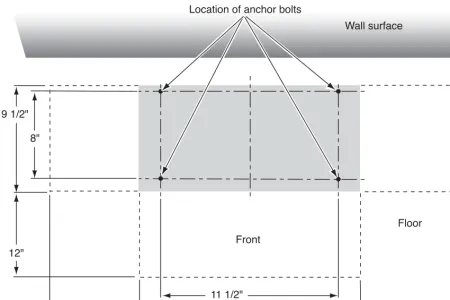
Securing the Cabinet to the Floor
(Figure 1-2 - Figure 1-4)
1. Install the mounting brackets on the floor providing the appropriate spacing as shown below.
Figure 1-2: INSTALLING THE MOUNTING BRACKETS
08931 30 - 22
Floor Front
Wall surface Location of anchor bolts
9 1/2"
8"
12"
12"
11 1/2"
Aspire S Hardware Manual Section 1: Installing the Cabinet ◆ 1-5
1
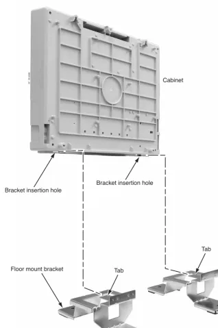
2. Attach the floor mounting brackets to the cabinet. Insert the tabs of the brackets into the slots on the bottom of the cabinet.
Figure 1-3: SECURE THE MOUNTING BRACKETS WITH SCREWS
0893130 - 20
Cabinet
Bracket insertion hole
Floor mount bracket
Bracket insertion hole
Tab
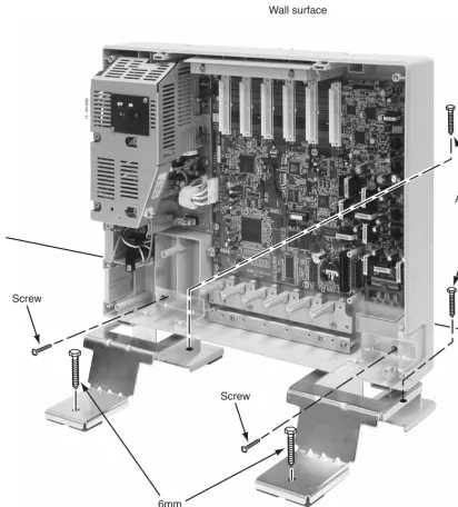
3. Secure the brackets to the cabinet with the screws provided with the bracket. Then secure the mounting brackets to the floor using 4 6mm anchor bolts.
Figure 1-4: SECURE THE MOUNTING BRACKET WITH SCREWS
0893130 - 21
Screw
6mm Anchor Bolt
6mm Anchor Bolt
Wall surface
Screw
Aspire S Hardware Manual Section 1: Installing the Cabinet ◆ 1-7
1
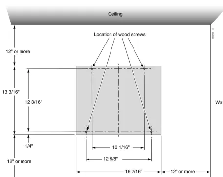
Securing the Cabinet to the Wall
(Figure 1-5 - Figure 1-8)
1. Install the two wood screws to the wall providing the appropriate spacing as shown below. The two top key-hole screws should protrude from the wall about 3/16” to allow the cabinet to slide over the screw heads.
It is suggested that plywood first be installed on the wall where the cabinet will be positioned.
This allows for secure anchoring of the screws which will be supporting the weight of the cabinet.
Figure 1-5: CABINET SPACE REQUIREMENTS
0893130 - 13
Floor surface
Wall surface Ceiling
Location of wood screws
13 3/16"
12 3/16"
1/4" 12" or more
12" or more
10 1/16"
12 5/8"
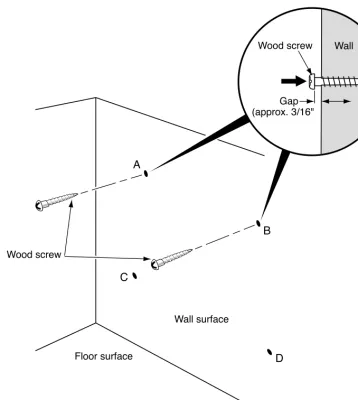
Figure 1-6: INSTALLING THE WOOD SCREWS
089313 0 - 14 Floor surface
Wall surface
A
B
C
D
Gap (approx. 3/16"
Wall Wood screw
Aspire S Hardware Manual Section 1: Installing the Cabinet ◆ 1-9
1
2. Lift the cabinet into position and slide the cabinet over the screws attached to the wall. Making sure the cabinet moves down to the top of the keyhole opening.
Figure 1-7: PLACE THE CABINET ON THE WALL
3. Secure the cabinet to the wall by inserting the two screws into the bottom half of the cabinet.
Figure 1-8: FASTEN CABINET TO WALL
0893130 - 18
Floor surface
Wall surface
0893130 - 19
Wall surface
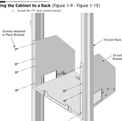
Securing the Cabinet to a Rack
(Figure 1-9 - Figure 1-12)
1. Install the 19” rack mount bracket.Figure 1-9: INSTALLING THE MOUNTING BRACKET ON THE RACK
0893100 - 44
19 inch Rack Screws attached
to Rack Bracket
Aspire S Hardware Manual Section 1: Installing the Cabinet ◆ 1-11
1
2. Remove the 2 screws from the front of the rack mount bracket.
Figure 1-10: REMOVE THE SCREWS FROM THE RACK
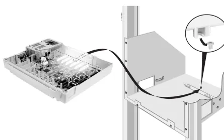
3. Place the cabinet in the rack, making sure the screw on the rack’s mounting bracket catches the cab-inet’s molded stop on the bottom of the cabinet. This will help secure the cabinet in place and pre-vent it from sliding backwards.
Figure 1-11: INSTALLING THE CABINET IN THE RACK
0893130 - 1
Aspire S Hardware Manual Section 1: Installing the Cabinet ◆ 1-13
1
4. Replace the screws in the front of the rack which were removed in step 2.
Figure 1-12: SECURING THE CABINET TO THE RACK
INSTALLING THE PCBS
PCB Installation
(Figure 1-13 - Figure 1-16)
1. Slide the PCB retaining bar back until you hear it click in place.
Do not loosen the screws.
Figure 1-13: MOVING THE RETAINING BAR 0893130-9
PCB Retaining Bar Push both ends when moving
Aspire S Hardware Manual Section 1: Installing the Cabinet ◆ 1-15
1
2. Insert the PCB along the guide rails and firmly plug in the PCB connector to the CPU.
Figure 1-14: INSERTING THE PCB
0893130-10 Connector
Guide rail (top)
Guide rail (bottom)
Connector in Cabinet (SLOT3 thru SLOT 8) PCB
3. Secure the PCB to the CPU by attaching the screw provided on the PCB as shown below.
Figure 1-15: SECURING THE PCB
0893130-5
Aspire S Hardware Manual Section 1: Installing the Cabinet ◆ 1-17
1
4. Move the PCB retaining bar back in place to secure to top of the PCBs.
Figure 1-16: MOVING THE RETAINING BAR BACK
0893130-7
PCB
GROUNDING THE CABINETS
Connecting the System Ground (Figure 1-17)
1. Ground the cabinet by connecting a 14 AWG wire from the ETH lug to a known earth ground, such as a copper plate or grounding rod.
Be cautious when using a cold water pipe that it’s completely copper and does not change to PVC/vinyl chloride pipe.
2. When installing a COIU or DIOPU PCB, connect the grounding wire of the PCB to the PBXG ter-minal plate and then run a grounding wiring from the PBXG terter-minal plate to a known earth ground using 14 AWG grounding wire.
The ETH and PBXG grounds should be separate - they should not be combined.
3. From the factory, the FG is already connected to the AC power source. No action is required.
Figure 1-17: GROUNDING THE CABINET
0893130-8
PCB Frame Ground
PBXG Connection Cable
Grounding Wire
To Known Earth Ground Grounding Wire
Connection Terminal PBXG Terminal Plate
Aspire S Hardware Manual Section 1: Installing the Cabinet ◆ 1-19
1
The ground lug descriptions are as follows:
● PBXG (CO/PBX Ground)
The grounding wire from the COIU or DIOPU PCBs are connected to the PBXG terminal plate. A grounding wire should then be connected from the PBXG terminal plate to a known earth ground when these PCBs are installed in the system.
This grounding wire should be separate from the ETH grounding wire.
● ETH (Earth Ground)
This ground lug is used for lightning protection. It should always be connected to the earth.
This grounding wire should be separate from the PBXG grounding wire.
● FG (Frame Ground)
COMPLETING THE INSTALLATION
Setting the Cable Pass-Through
(Figure 1-18 - Figure 1-20)
The each cabinet has two cable pass-throughs - one each on the left and right sides of the cabinet. The block plate should be in place for any unused pass-through in order to help keep dust out of the cabinet.
1. There are two opening options - one setting provides a small pass-through, the other provides a larger pass-through. Determine which type is required for the cabinet.
Figure 1-18: CABLE PASS-THROUGH
0893130-15
Block Plate
Aspire S Hardware Manual Section 1: Installing the Cabinet ◆ 1-21
1
2. For the small pass-through, turn the block plate upside down and replace into the slot.
Figure 1-19: SMALL CABLE PASS-THROUGH
3. For the large pass-through, remove the block plate and store it in the bottom-right corner of the cabinet.
Figure 1-20: LARGE CABLE PASS-THROUGH
0893130 - 16
Reinstalling the Front Cover
(Figure 1-21 - Figure 1-22)
1. Line up the hooks on the front cover with the slots in the cabinet and insert the cover.
Figure 1-21: RE-INSTALLING THE FRONT COVER
2. Lower the cover.
Figure 1-22: LOWER THE FRONT COVER
3. Tighten the four cover retaining screws.
A label is located on the right side of the cabinet which can be used to enter the date when the battery should be replaced. In case of a power failure, this battery provides back-up of system data
and RAM memory for approximately 30 months. Program 90-11-01 can also be set to define an
extension to receive an indication on their display when the battery is low.
0893130 -3
Hook Hook Front Cover
Aspire S Hardware Manual Section 2: PCB Installation and Startup ◆ 2-1
2
Section 2:
PCB Installation and Startup
Section 2: PCB Installation and Startup
PCB LAYOUT
PCB Location
Determine the slot position for each PCB. In the cabinet:
● Slots 3 - 8 are universal (any type of PCB can be installed). The only restriction is that an ESIU PCB can not be placed into slots 7 or 8 as there are not enough conversation channels.
Important Notes
• Make sure to follow the steps indicated in Powering Up the System (page 2-40) for an initial system install. This will ensure that you start the system with the default system settings. • To delete a PCB from the system, power down the system and then remove the PCB from the
sys-tem cabinet. Power the system back up and use Program 90-05-01 to delete the slot definition.
• Whenever powering down the system, check to make sure the only LED flashing on the CPU
card itself (in the lower left-hand corner) is the LD2 LED (the LED located farthest right in the
line of LEDs). This LED is located in the lower left-hand corner of the CPU. It should be fl
ash-ing 0.5 seconds on/off (a slow flash). If it’s flashing fast or if any other LEDS are flashing on the CPU, wait until they stop or else the system data may be corrupted.
PCB INSTALLATION
Handling the PCBs
The PCBs are sensitive to static discharge. To minimize static discharge, keep PCBs in static free bags when not installed. Observe the following when installing or removing a PCB:
● Ground the cabinet.
● Wear a grounded wrist strap to install/remove any PCBs.
● Do not touch PCB components. Handle the PCBs in the corners.
● All PCBs must be installed with the system power off.
Installing an Extension or Trunk PCB
(Figure 2-2)
To install an extension/trunk PCB:● Power down the system.
Whenever powering down the system, check to make sure the only LED flashing on the CPU
card itself is the LD2 LED (farthest right of the LEDs). This LED is located in the lower left-hand
corner of the CPU. If any other LEDS are flashing on the CPU, wait until they stop or else the
sys-tem data may be corrupted.
● Push the retaining bar up (or back depending on the cabinet’s position).
Figure 2-1: MOVING THE RETAINING BAR 0893130-9
PCB Retaining Bar Push both ends when moving
Aspire S Hardware Manual Section 2: PCB Installation and Startup ◆ 2-3
2
● Insert the PCB within the guide rail and push the PCB securely into position. After installing all the PCBs, the PCB retaining bar should be moved back into position and the screws for each of the PCBs should be tightened.
Figure 2-2: INSERTING PCBS
0893130-7
PCB
PCB Retaining Bar
0893130-5
Screw
0893130-10
Connector
Guide rail (top)
Guide rail (bottom)
Connector in Cabinet (SLOT3 thru SLOT 8) PCB
Removing an Extension or Trunk PCB
Whenever powering down the system, check to make sure the only LED flashing on the CPU card itself is the
LD2 LED (farthest right). This LED is located in the lower left-hand corner of the CPU. If any other LEDS
are flashing on the CPU, wait until they stop or else the system data may be corrupted.
To remove an extension/trunk PCB:
● Turn off the system power by pressing the ON/OFF switch on the cabinet.
Whenever powering down the system, check to make sure the only LED flashing on the CPU
card itself is the LD2 LED (farthest right of the LEDs). This LED is located in the lower left-hand
corner of the CPU. If any other LEDS are flashing on the CPU, wait until they stop or else the sys-tem data may be corrupted.
● All PCBs must be installed with the system power off.
Uninstalling a PCB Slot Through Software
Aspire S Hardware Manual Section 2: PCB Installation and Startup ◆ 2-5
2
Where to Install the PCBs
Maximum Configuration: With Software 2.08-2.21 Only
8 Trunks
26 Extensions (24 digital and analog, 2 analog only) - Includes a maximum of 16 IP Extensions 24 Virtual Extensions
With Software 2.50 and Higher 8 Trunks
26 Extensions (24 digital and analog, 2 analog only) 16 IP Extensions or APR-B2 Extensions
8 Special Terminals - Reserved for Intramail Only (ports 43-50) 24 Virtual Extensions
The system’s universal architecture gives you great flexibility when installing PCBs. You can install a PCB in any slot, provided you follow the guidelines in the chart below.
Item Description Max.
CPU (MBU) 32-Bit Central Processing Unit 1
DSPDB DSP Resource - Daughter Board 1 installed on CPU ENTU-S LAN CTI Ethernet Interface Board 1 installed on CPU 8ESIU-S 8 Digital Stations 2 - Can not be installed in slots
7 or 8
4SLIU-S 4 Analog Stations 4
4SLIDB-S 4 Analog Stations - Daughter Board 0 - If 4 4SLIU PCBs installed 1 - If 3 4SLIU PCBs installed 2 - If 2 4SLIU PCBs installed 4COIU-S 4 Analog/Loop Start Trunks (no ground start) 2
2BRIU-S 2 Two-Channel BRI Circuits 2 - When used as T-Point
2DIOPU-S 2 DID/OPX Trunks 4
4VOIPU-S 4 VoIP Media Gateway 3
Central Processing Unit (CPU) PCB
(Figure 2-3)
The CPU, which is pre-installed, controls all the functions and operations of the Aspire system using the system software loaded into the CPU memory. One 32-bit CPU is installed in the system cabinet. The CPU provides the following:
● Accomodates up to 34 ports (8 trunks x 26 extensions)
● 8 digital station connections
A 2PGDAD module cannot be connected to port 1 or port 2. ● 2 analog station connections (no Message Wait lamping)
● 4 diagnostic LEDs which indicate the status of various system functions
During normal operation, the “LD2” LED will be flashing. The remaining LEDs can flash on or
off depending on the current system operation. ● Time Switch (383 ch)
● Digital Phase Locked Loop (DPLL): digital phase synchronization loop
● SFLM Generation
● DSP (Digital Signal Processor: provides C-Channel control
● Tone Generation
● DTMF Tone Sender/Receiver
● System Tone Sender
● MFC Tone Sender
● MF Signal Sender (Sends caller information to CO for E911)
● Call Progress Tone Detector
● C-Channel Control
● Time Switch control
● HDLC (High-Level Data Link Control) Packet Proceessing
● Conference; 32 Channels
● Caller ID Receiver/Generation; 16 Channels
● A load button which is used for initial system startup or when upgrading system software
● One Serial Port (requires null modem/cross-over cable)
● One Compact Flash Card Slot
● One Audio Input Terminal (external MOH/BGM source)
● General Purpose Control Terminal
● Hold Tone Transmit
● IP
● Real Time Clock (tolerance 30 seconds/month)
● Internal MOH Generation
● One Connector for PAL EPROM
● One lithium battery (Sony CR2032 or equivalent) which provides battery back-up of system data and RAM memory for approximately 30 months
Aspire S Hardware Manual Section 2: PCB Installation and Startup ◆ 2-7
2
Figure 2-3: CPU
! IMPORTANT !
While the system is powered up, data may be written to the S-RAM or flash memory at any time. Before pow-ering down the system, verify that of the 4 LEDs in the lower left corner of the CPU, only LD2 is flashing. This LED is the farthest right of the LEDs. It should be flashing 0.5 seconds on/off (a slow flash). If it’s flashing fast or if any other LEDS are flashing on the CPU, wait until they stop or else the system data may be corrupted.
Turning off the power when other LEDs are flashing may corrupt the flash or S-RAM data. If the flash memory
becomes corrupted, the system may not come up. If the S-RAM data is corrupted, the telephones may have erratic operation.
When powering the system up or down, wait 10 seconds before pressing the button again. This allows the sys-tem to complete the startup/shutdown process.
0893130-23
CN1 Serial Cable Connector (D-Sub 9-pin male) Slots 3-8
CN4 DSPDB Connector
LD6, LD7
CN23
Audio In (BGM/MOH) and General Purpose Relay CN22
Connector for analog terminals (SLI1,SLI2)
CN21
Connector for digital phones (ESI5 - ESI8)
CN20
Connector for digital phones (ESI1 - ESI4)
CN7
ENTU Connector
CN5
Compact Flash Card Connector
CN6
ENTU Connector
LD5
Compact Flash Card LED CN30 ROM Board Connector BT1 Battery (CR2032 3.0V) SW4 Boot Code Update Switch LD2 LD4 LD3 LD1 SW1 Load Button SW3
Switch Settings and LED Indications
The LED indications on the CPU represent the following:
● RUN (LD2) = Indicates the CPU is operating
● LED 1 (LD1), 3 (LD3) and 4 (LD4) = Indicate system alarms
● LED 5 (LD5) = Status of Compact Flash Card (off with no flash card installed)
● LED 6 (LD6) and 7 (LD7) = Indicates the status of single line ports 1 and 2 (off when on-hook)
Refer to Program 90-10 : System Alarm Setup for details on assigning alarm LEDs.
Switch SettingSwitch Operation
SW1 - Load Switch - While powering up the system and holding the SW1 switch (SW3-2 switch set to off):
• With a PC-ATA: System software is updated.
• Without a PC-ATA: System boots loading stored software.
• With a Card Other Than a PC-ATA: The card is ignored and the sys-tem boots loading stored software.
While powering up the system without holding the SW1 switch:
• The system boots loading software stored in flash memory.
SW3 3
1
Debugging Mode (CN1 connector used for debugging) Normal Mode (CN1 connector used for serial interface)
SW4 3
1
(Factory Use) Used to initially load system software Normal Mode
LED Indication
Status
RUN (LD2) LED1 LED3 LED4 LED5
On Off Off Off On Steady with
card installed
System starting up
Off Off Off Off On Steady with
card installed
System initializing
Off On Off Access Blink On Steady with
card installed
Initializing or formatting the disk
Off Off On On On Steady with
card installed
Boot program is initializing in the
flash memory
Off On On Access Blink On Steady with
card installed
Loading system software
On Blinking Blinking Blinking On Steady with card installed
Completing system program update
On Blinking Off Off On Steady with
card installed
Completing boot software update
On Blinking Blinking Off On Steady with
card installed
Completing disk formatting (SRAM, Flash)
Aspire S Hardware Manual Section 2: PCB Installation and Startup ◆ 2-9
2
Blinking Off Off On On Steady with
card installed
FPGA version error
Blinking Off On Off On Steady with
card installed
SRAM error
Blinking Off On On On Steady with
card installed
Flash memory booting (start-up) error
Blinking On On On On Steady with
card installed
Flash memory data error
Blinking Blinking Blinking Blinking On Steady with card installed
Read error of system program
Blinking Off Off Off On Steady with
card installed
Running normally LED Indication
Status
Connector Pin-Outs on CPU
Serial Cable Connector - CN1 (D-Sub 9-Pin Male) (Null Modem/Cross-Over Cable Used)
Pin No. Signal
1 DCD
2 RxD
3 TxD
4 DTR
5 GND
6 DSR
7 RTS
8 CTS
9
-Digital Station RJ61 Cable Connector - CN20
Pin No. Connection
1 Ring for port 4
2 Ring for port 3
3 Ring for port 2
4 Tip for port 1
5 Ring for port 1
6 Tip for port 2
7 Tip for port 3
8 Tip for port 4
Digital Station RJ61 Cable Connectors - CN21
Pin No. Connection
1 Ring for port 8
2 Ring for port 7
3 Ring for port 6
4 Tip for port 5
5 Ring for port 5
6 Tip for port 6
7 Tip for port 7
8 Tip for port 8
1 2 3 4 5
6 7 8 9
12345678
Aspire S Hardware Manual Section 2: PCB Installation and Startup ◆ 2-11
2
CPU Installation
1. Install the battery on the CPU. The polarity “+” symbol must be on top.
2. Install the DSPDBU daughter board if required. Refer to DSPDB Daughter Board (Figure 2-4,
Figure 2-5) (page 2-13).
3. If external BGM or MOH is being installed, plug an RJ61 connector into the CN23 connector on the CPU. The other end of the cable plugs into the music source.
Refer to the PGDAD Module in the Telephones and Optional Equipment section for details on connecting to a music source.
Note that Message Waiting lamping is not provided on the two analog ports on the CPU.
4. Assign the purpose of the General Purpose Relay in Program 10-21-01. Analog Station RJ61 Cable Connector - CN22
Pin No. Connection
1 2
3 Ring for port 2
4 Tip for port 1
5 Ring for port 1
6 Tip for port 2
7 8 • Polarity reversal feature available • No Message Wait lamping
External MOH/BGM Source/Relay (External Speaker and Night Mode) RJ61 Cable Connector - CN23
CPU Connector Modular ConnectorPin No. Signal
1
-2
-3 EXCNT - Relay
4 EXMOH/BGM Music
Source
5 EXMOH/BGM Music
Source
6 EXCNT - Relay
7
-8
-• Pins 4 and 5: External Music on Hold/BGM Input, Input Impedance 600 ohm/ 1 kHz
• Pins 3 and 6: Relay = DC Max. 24 VDC, 0.5A - AC Max. 120VAC, 0.25A 12345678
● When the system software is upgraded, the flash memory is updated with the new software version. You can use the Hot or Cold start-up methods or upgrade your system software using the steps which follow.
● Customer information is stored in the RAM memory and, in case of a power failure, will be restored. The lithium battery in the system saves the RAM memory when power is lost.
Resetting the System:
! IMPORTANT !
While the system is powered up, data may be written to the S-RAM or flash memory at any time. Before powering down the system, verify that of the 4 LEDs in the lower left corner of the CPU, only LD2 is flashing (this is the LED located farthest right of the LEDs). It should be flashing 0.5 seconds on/off (a slow flash). If it’s flashing fast or if any other LEDS are flashing on the CPU, wait until they stop.
Turning off the power when other LEDs are flashing may corrupt the flash or S-RAM data. If the
flash memory becomes corrupted, the system may not come up. If the S-RAM data is corrupted, the
telephones may have erratic operation.
To Perform a Cold Start:
1. If installed, pull out the compact flash card.
With the compact flash card installed, the system will error and not boot up correctly.
2. Push the power button on the cabinet to power down the system.
When powering the system up or down, wait 10 seconds before pressing the button again. This allows the system to complete the startup/shutdown process.
3. Once the system has powered down, push in and hold the Load button. 4. Press the power button to power the system back up.
5. Continue holding the Load button for approximately 3 seconds. 6. Release the Load button.
7. When the system has completed reloading the software (approximately 2 minutes), the Status LED (LD2) will be flashing on the CPU.
To Perform a Hot Start:
System software loaded from flash memory and the customer data is loaded from RAM memory.
1. Push the power button on the cabinet to power down the system. Once it has powered down, wait 10 seconds then press the button again to power the system back up.
When powering the system up or down, wait 10 seconds before pressing the button again. This allows the system to complete the startup/shutdown process.
2. Wait approximately 2 minutes.
3. When the system has completed reloading the software, the Status LED (LD2) will be flashing on the CPU.
Performing a Software Upgrade:
Refer to Saving Your Configuration (page 2-44), Backing Up/Restoring a Database (page 2-44), Using
Flash Cards for System Software (page 2-45), and Upgrading Software (page 2-46) for complete details
Aspire S Hardware Manual Section 2: PCB Installation and Startup ◆ 2-13
2
DSPDB Daughter Board
(Figure 2-4, Figure 2-5)
The DSPDB provides the option for the VRS (Voice Response System) feature. This daughter board is mounted on the CPU and provides:
● 8 VRS Circuits with a VRS Flash Card Installed (replays up to 8 circuits simultaneously; records up to 8 cir-cuits simultaneously)
● Compact Flash Slot for VRS or IntraMail Feature
There are no DTMF receivers provided when this daughter board is installed on the CPU.
To install a DSPDB Daughter Board:
1. Included with the DSPDB are four spacers. Install one spacer in each corner of the daughter board. Make sure to attach the spacers from the back of the daughter board so when installed, the compact
flash slot is facing up.
2. Position the daughter board over the CN4 connector on the CPU. Push the board into the connector on the CPU. Gently push the corners of the daughter board down so the spacers lock into the CPU.
To remove the daughter board, use pliers to squeeze the top of the spacers together, then gently pull the daughter board off.
Figure 2-4: DSPDB DAUGHTER BOARD INSTALLATION
0893130-25
DSPDB CN1
CN4
CPU
To Upgrade the DSPDB Compact Flash Card:
1. With the system power off, remove the compact flash card from the DSPDB daughter board. 2. Insert the new compact flash card.
Figure 2-5: REMOVING THE COMPACT FLASH CARD
Aspire S Hardware Manual Section 2: PCB Installation and Startup ◆ 2-15
2
LAN Connection (ENTU) PCB
(Figure 2-6)
An ENTU PCB is required when a VoIP PCB is installed. If the ENTU is not installed, the system will not start up. In addition, an ENTU would be required for a WebPro/PCPro LAN connection.
The ENTU PCB provides a LAN connector which is compatible with 100Base-TX and 10Base-T. This PCB is compatible in LAN applications using 10Mbps and 100Mbps. All ports will automatically identify and switch 100Base-TX, 10Base-T and Full/Half Duplex.
The VoIP PCB, which is required in order for IP telephones to communicate with non-VoIP Aspire phones, as well as to place or receive outside calls, must be connected to an external switching hub.
The PCB plugs into the CN6 and CN7 connectors on the CPU, with a maximum of 1 per system. Each PCB provides an RJ61 port connector. This is used to connect to a LAN terminal or external switching hub. Depending on the type of LAN terminal, the PCB may not be able to detect the difference between straight cable and cross-cable automatically. If auto-crossover is not functioning, use straight cable for that terminal connection.
If PoE (power over ethernet) is to be used to eliminate the separate power adapters, a separate power source is required. It is recommended that you use a power switch and/or power hub which is IEEE 802.3AF com-pliant. For example, the PowerDsine 6xxx series of products is unique in the fact that in addition to offering IEEE 802.3AF support, it also provides for the NEC proprietary detection and, therefore, the ILPA (In Line Power Adapter) is not required. For systems which require layer 2 switching capability and PoE, the NEC BlueFire 200/24 switch is recommended. This unit provides layer 2 switch capability in addition to being able to supply ethernet power to 24 NEC IP terminals. For this unit, power feeding is through the signal pair (1/2, 3/6) or spare pair (4/5, 7/8).
Refer to Section 6: LAN Connection (page 6-1) for additional information on using PoE on the Aspire.
Specifications
● LAN Family Standard: Complies with 10Base-T and 100Base-TX (IEEE802.3)
● Access Method: CSMA/CD
● Transmission Line/Channel Interface: 10Base-T/100Base-TX = 1 port
● LAN Family Interface (Layer 1):
Transmission Speed: 10Mbps/100Mbps Auto Negotiation
Cable: LAN Category 5 or higher - Straight/Cross cable auto negotiation (auto crossover)
LED Indications
LED Function LED Status Operation Status
LD1 ACT
LAN Operation Status Green Flashing Communicating Data Green Off Not Activated LD2
LINK
LAN Operation Status Red On Link Established
Connector Pin-Outs on ENTU
Installing the ENTU:
1. Included with the ENTU is one plastic spacer. Install the spacer in the corner of the daughter board which will not have a support provided by the CPU. Make sure to attach the spacer from the back of the daughter board so when installed, the connectors are facing up.
2. Position the ENTU PCB over the CN6 connector on the CPU. Push the board into the connector on the CPU. Gently push the corner of the daughter board down so the spacer locks into the CPU.
To remove the daughter board, use pliers to squeeze the top of the spacer together, then gently pull the daughter board off.
3. Using the three screws provided with the ENTU PCB, secure the remaining three corners of the PCB to the CPU.
Once the system has been powered up, with normal operation, the status LED will flash fast. If
trouble was found during the self diagnostics routine, the status LED will flash slowly.
4. Using the ferrite core provided with the ENTU PCB, wrap the end of the ethernet cable which is closest to the ENTU’s CN2 connector once around the ferrite core.
5. Plug the ethernet cable into the CN2 connector.
6. Refer to the Aspire Software Manual (P/N 0893200) or the VoIP Feature Supplement (P/N 0893204) for required VoIP programming.
Ethernet Cable Connector - CN2 (RJ45) (10Base-T/100Base-TX Port)
Pin No. Signal
1 Tx+
2
Tx-3 Rx+
4
-5
-6
Rx-7
-8
-12345678
089313
0-32
CN2 - RJ 45 Ethernet Connector
CN3 CPU Connection (For earth ground)
Aspire S Hardware Manual Section 2: PCB Installation and Startup ◆ 2-17
2
Digital Station (8ESIU-S) PCB
(Figure 2-7)
The 8ESIU-S PCB provides:● 8 digital extension circuits (used for digital telephones, DSS consoles, 1SLTAD adapters, 2PGDAD adapters)
The 8ESIU-S is not rated for OPX use. It is recommended that a 2DIOPU-S PCB be used instead (it supports analog DID and single line telephone interface functions, such as Off-Premise Extensions). ● 1 extension status LED (indicates status for 4 extensions)
● 1 PCB status LED
The CN3 and CN4 connectors each provide connection to 4 digital station ports. The ESIU-S requires one universal slot, with a maximum of 2 PCB’s per system. Note that this PCB can not be installed in slot 7 or 8.
The 8ESIU-S consumes 8 ports ranging between ports 01-26. There must be enough available ports in order for the Aspire system to recognize an 8ESIU-S PCB.
LED Indications
LED Function LED Status Operation Status
LD2
(PCB Status)
Indicates the status of the PCB.
Green On Initializing Green Flashing
(slow flash)
Initialization problem occurred during self-check. Green Flashing
(100ms On/Off)
Operating normally
Green Off Downloading LD1 Indicates the status of
terminals 1-8.
Connector Pin-Outs on ESIU
RJ61 Cable Connector - CN4
Pin No. Connection
1 Ring for port 4
2 Ring for port 3
3 Ring for port 2
4 Tip for port 1
5 Ring for port 1
6 Tip for port 2
7 Tip for port 3
8 Tip for port 4
RJ61 Cable Connector - CN3
Pin No. Connection
1 Ring for port 8
2 Ring for port 7
3 Ring for port 6
4 Tip for port 5
5 Ring for port 5
6 Tip for port 6
7 Tip for port 7
8 Tip for port 8
12345678
Aspire S Hardware Manual Section 2: PCB Installation and Startup ◆ 2-19
2
To install the ESIU PCB:1. Install the ESIU into a slot.
Note that this PCB can not be installed in slot 7 or 8.
2. Tighten the screw on the PCB to secure the card to the cabinet.
Figure 2-7: ESIU INSTALLATION
0893130-29
CN6 CN7
CN4 CN3 LD2 PCB Status LED
Analog Station (4SLIU-S) PCB
(Figure 2-8)
The 4SLIU-S PCB provides:● 4 analog extension ports (used for on-premise analog telephones, fax machines, and analog modems)
The 4SLIU-S is not rated for OPX use. It is recommended that a 2DIOPU-S PCB be used instead (it supports analog DID and single line telephone interface functions, such as Off-Premise Extensions). ● 4 extension status LEDs
● 1 PCB status LED
● Connector for 4SLIDB-S Daughter Board
● Ring Generator
● Message Wait Lamping Ability
Note: When connecting a fax machine or analog modem, make sure to set Program 15-03-03 to ‘1’ (special terminal) to avoid communication problems.
The CN3 connector provides connection to 4 analog station ports and are not polarity sensitive. The 4SLIU-S is installed in a universal slot with a maximum number of 4 PCBs per system. This number of PCBs installed will reduce the number of 4SLIDB-S PCBs which can be installed. If 3 4SLIU-S PCBs are installed, only 1 4SLIDB-S can be installed. If 4SLIU-S PCBs are installed, the 4SLIDB-S can not be used. There must be enough available ports in order for the Aspire system to recognize an 4SLIU-S PCB.
LED Indications
Connector Pin-Outs on 4SLIU-S
LED Function LED Status Operation Status
LD1
(PCB Status)
Indicates the status of the PCB.
Green On Initializing Green Flashing
(slow flash)
Initialization problem occurred during self-check. Green Flashing
(100ms On/Off)
Operating normally
Green Off Downloading LD2 - LD5 Indicates the status of
terminals 1-4.
Red On Terminal in use Red Off Terminal idle
RJ61 Cable Connector - CN3
Pin No. Connection
Aspire S Hardware Manual Section 2: PCB Installation and Startup ◆ 2-21
2
Installing an 4SLIU-S PCB:1. If the 4SLIDB-S is to be used, install this prior to inserting the 4SLIU-S PCB into the cabinet. 2. Install the 4SLIU-S into the slot.
3. Tighten the screw on the PCB to secure the card to the cabinet.
Figure 2-8: 4SLIU-S INSTALLATION
0893130-30
CN5 4SLIDB Connector
LD1 PCB Status LED
LD2 - LD5 Line Status LEDs
CN4 SLIDB PCB Earth Ground Connection
Analog Station (4SLIDB-S) Daughter Board
(Figure 2-9 - Figure 2-10)
The 4SLIDB-S daughter board provides:● 4 analog extension ports (used for on-premise analog telephones, fax machines, and analog modems)
● Connector for 4SLIU-S PCB
● Ring Generator
● Message Wait Lamping Ability
Note: When connecting a fax machine or analog modem, make sure to set Program 15-03-03 to ‘1’ (special terminal) to avoid communication problems.
The CN3 connector provides connection to 4 analog station ports and are not polarity sensi-tive. The 4SLIDB-S is installed on the 4SLIU-S
PCB. Up to 2 PCBs can be installed in the system maximum, but this number may be reduced depending on how many 4SLIU-S PCBs are installed. If 3 4SLIU-S PCBs are installed, only 1 4SLIDB-S can be installed. If 4SLIU-S PCBs are installed, the 4SLIDB-S can not be used.
LED Indications
Connector Pin-Outs on 4SLIDB-S
LED Function LED Status Operation Status
LD1 - LD4 Indicates the status of terminals 5-8.
Red On Terminal in use Red Off Terminal idle
RJ61 Cable Connector - CN3
Pin No. Connection
1 CH4 L1 (tip for port 4) 2 CH3 L1 (tip for port 3) 3 CH2 L1 (tip for port 2) 4 CH1 L2 (ring for port 1) 5 CH1 L1 (tip for port 1) 6 CH2 L2 (ring for port 2) 7 CH3 L2 (ring for port 3) 8 CH4 L2 (ring for port 4)
0893130-31
LD1 - LD4 Live Status LEDs (on back of PCB)
CN3
Analog Ports 1-4
CN4
SLIU PCB Earth Ground Connector
Figure 2-9: 4SLIDB-S PCB
Aspire S Hardware Manual Section 2: PCB Installation and Startup ◆ 2-23
2
Installing an 4SLIDB-S Daughter Board:1. Included with the 4SLIDB-S are four plastic spacers. Place a plastic spacer in each corner of the PCB. Make sure to attach the spacers on the front of the daughter board so when installed, the com-ponents are facing the 4SLIU-S PCB.
2. Position the 4SLIDB-S’s CN1 connector over the CN5 connector on the 4SLIU-S PCB. Press the boards together, ensuring the plastic spacers lock in place.
3. Install the 4SLIU-S PCB into the slot.
Figure 2-10: 8SLIDB-S INSTALLATION
0893130 -24 4SLIDB
CN1
CN4
CN4
CN5
4SLIU
Analog Trunk (4COIU-S) PCB
(Figure 2-11)
The Analog Trunk (COIU-S) PCB provides:● 4 analog loop start line/trunk circuits - no ground start is provided
● 4 trunk status LEDs
● 4 Caller ID Circuits
● 1 Power Failure Transfer Circuit
● 1 PCB status LED
The CN5 and CN7 connectors each provide connection to 2 analog trunk ports, which are polarity sensitive
(tip to tip, ring to ring). The power failure circuit, however, is not polarity sensitive. A maximum of 2
4COIUs per system is allowed.
LED Indications
LED Function LED Status Operation Status
LD5
(PCB Status)
Indicates the status of the PCB.
Green On Initializing Green Flashing
(slow flash)
Initialization problem occurred during self-check. Green Flashing
(100ms On/Off)
Operating normally
Green Off Downloading LD1 - LD4 Indicates the status of
the lines.
Red On Line in use
Aspire S Hardware Manual Section 2: PCB Installation and Startup ◆ 2-25
2
Connector Pin-Outs on COIU-S PCBRJ61 Cable Connector - CN5
The CN5 and CN7 connectors are polarity sensitive (tip to tip, ring to ring).
Pin No. Connection
1
-2 SLT Interface
Power Failure Circuit - Tip
3 Circuit 2 - Tip
4 Circuit 1 - Ring
5 Circuit 1 - Tip
6 Circuit 2 - Ring
7 SLT Interface
Power Failure Circuit - Ring
8
-RJ61 Cable Connector - CN7
Pin No. Connection
1
-2
-3 Circuit 4 - Tip
4 Circuit 3 - Ring
5 Circuit 3 - Tip
6 Circuit 4 - Ring
7
-8
-12345678
Installing the Analog Trunk PCB: 1. Install the COIU-S into a slot.
The trunk ports are polarity sensitive (tip to tip, ring to ring). Be sure the wiring is correct.
Once the system is powered up, with normal operation, the status LED will flash fast. If trouble
was found during the self diagnostics routine, the status LED will flash slowly.
2. Tighten the screw on the PCB to secure the card to the cabinet.
.
Aspire S Hardware Manual Section 2: PCB Installation and Startup ◆ 2-27
2
Direct Inward Dial (DID) (2DIOPU-S) PCB
(Figure 2-12)
The 2DIOPU-S PCB, with software 2.21 or higher, supports the analog DID and single line telephone inter-face functions (such as Off-Premise Extension). The function type is assigned in programming for each port. The DIOPU-S PCB provides:
● 2 DID/OPX trunk circuits
● 2 DID/OPX trunk status LEDs
● 1 PCB status LED
● 1 PBXG Grounding Wire
The CN201 connector provides connection to 2 analog DID trunk ports, which are polarity sensitive (tip to
tip, ring to ring). The OPX circuits, however, are not polarity sensitive. The DIOPU-S requires one universal
slot, with 4 maximum PCBs per system. The system will assign either trunk or extension ports to the PCB based on the system programming (10-03-01). The PCB provides track resistance of 1500 ohms (PB loop) and 3000 ohms (DP loop) which includes the DC resistance of the terminal.
.
LED Indications
Connector Pin-Outs on DIOPU-S PCB
Installing the Direct Inward Dial PCB: 1. Install the DIOPU-S PCB into a slot.
2. Connect the PBXG grounding wire to the PBXG grounding terminal in the cabinet.
The analog DID trunk ports are polarity sensitive (tip to tip, ring to ring). The OPX circuits,
however, are not polarity sensitive. Be sure the wiring is correct for the application.
Once the system is powered up, with normal operation, the status LED will flash fast. If trouble
was found during the self diagnostics routine, the status LED will flash slowly.
3. Tighten the screw on the PCB to secure the card to the cabinet.
LED Function LED Status Operation Status
LD1
(PCB Status)
Indicates the status of the PCB.
Green On Initializing Green Flashing
(slow flash)
Initialization problem occurred during self-check. Green Flashing
(100ms On/Off)
Operating normally
Green Off Downloading LD2 - LD3 Indicates the status of
the lines.
Red On Line in use
Red Off Line idle
RJ61 Cable Connector - CN201
Pin No. Connection
1 N/A
2 N/A
3 Tip for port 2
4 Ring for port 1
5 Tip for port 1
6 Ring for port 2
7 N/A
8 N/A
• Connect the tip to the ground side and the ring to the -48V side when wiring for analog DID trunk ports.
Aspire S Hardware Manual Section 2: PCB Installation and Startup ◆ 2-29
2
BRI (2BRIU-S) Interface PCB
(Figure 2-13)
Check with your NEC Sales Representative for availability of this PCB.
The BRI PCB provides:
● 2 2-Channel Circuits (2B + D) configured as T-Bus
● 64 Kb/s Clear B-Channel and 16 Kb/s D-Channel
● 4 trunk/extension status LEDs
● 1 PCB status LED
● 1 run/block switch
The BRI Interface PCB uses a single universal slot. A maximum of 2 BRIU-S PCBs can be installed when used as T-Bus. Each PCB connects to the network via an NTI Network Termination. With the maximum number of PCBs installed, the following can be provided:
● The 2BRIU-S, when used as T-Bus, provides 2 BRI circuits and 4 BRI channels. A maximum of 7 ISDN terminals can be connected between an external DSU and the 2BRIU-S PCB.
The trunk circuit can be connected to either an ISDN trunk or ISDN telephone set, depending on the SW102 and SW202 switch settings.
Setting the SW100-SW200 Switches
In the following cases, the SW100-SW200 switches should be set to the ON position:
● When the channel is assigned as a T-Bus Point-to-Point.
● With T-Bus Point-to-Multipoint and if the system is connected at the end of the multipoint. Otherwise, the SW100-SW200 switches should be set to the OFF position.
Switch
Name PositionSwitch Result Comments
SW102 SW202
T T-Bus Connection
S S-Bus Connection Not currently used. SW100
SW200
ON Termination resistor is ON This switch should be set to ON:
1. When T-Bus with Point-to-Point is selected. 2. When T-Bus with Point-to-Multipoint is selected and if the connection to the Aspire system at the last port of the Bus connection.
OFF Termination resistor is OFF When T-Bus with Point-to-Multipoint is selected and if the Aspire system is not connected to the last port of the Bus connection, this switch should be OFF.
CN102 CN202
ON With S-Bus selected, the Feeding Power is supplied to the terminal.
Not currently used.
-If S-Bus is selected, this switch should be ON. OFF With S-Bus selected, the Feeding
Power is not supplied to the terminal.
Not currently used.
LED Indications
Connector Pin-Outs on BRIU-S PCB
LED Function LED Status Operation Status
LD5
(PCB Status)
Indicates the status of the PCB.
Green On Initializing Green Flashing
(slow flash)
Initialization problem occurred during self-check. Green Flashing
(100ms On/Off)
Operating normally
Green Off Downloading LD1 - LD2 Indicates the Layer 1
link status of the lines.
Red On Layer 1 link established
Red Off No link
RJ61 Cable Connector - CN2 T-Bus Connection
The CN2 connector is polarity sensitive (tip to tip, ring to ring).
Pin No. Connection
1
-2
-3 TA +
4 RA +
5 RB
-6 TB
-7
-8
-T-Bus Connection
Pin-Out for ISDN Cable at External DSU and Mod Jack
Pin No.
Connection on DSU Side Connection on Mod Jack
Terminal DSU Terminal DSU
1 - - -
-2 - - -
-3 TA + Rx + TA + Tx +
4 RA + Tx + RA + Rx +
5 RB - Tx - RB - Rx
-6 TB - Rx - TB - Tx
-7 - - -
-8 - - -
Aspire S Hardware Manual Section 2: PCB Installation and Startup ◆ 2-31
2
To install a BRI Interface PCB:1. Set the SWn02 jumpers on the BRI PCB for either T-Bus or S-Bus. 2. Set the SWn00 jumpers as either terminated or unterminated.
3. Set the CNn02 jumpers to either provide power (with S-Bus) or not to supply power (with T-Bus). 4. Plug the BRI PCB into the system cabinet.
Once the system is powered up, with normal operation, the status LED will flash fast. If trouble
was found during the self diagnostics routine, the status LED will flash slow.
Once connected, the ISDN Layer Link Status LEDs will be on steady when the Layer 1 link is established. If there is no link, the LED will be off.
5. Connect the cable from the NT1 Network Termination cable to the CN2 connector on the BRI PCB. 6. Tighten the screw on the PCB to secure the card to the cabinet.
Figure 2-13: BRI PCB INSTALLATION
0893130-28
CN102 - Power Feed Selector for Terminal
SW100
Sets termination impedance
SW102
Selects 'T' or 'S' Bus Interface
SW200
Sets termination impedance
SW202
Selects 'T' or 'S' Bus Interface CN202 - Power Feed Selector for Terminal
CN2
RJ61 ISDN Trunk Connector (Trunk 2)
CN2
RJ61 ISDN Trunk Connector (Trunk 1)
Voice Mail - IntraMail
(Figure 2-14)
A DSPDB daughter board is required for either version of IntraMail.
4 Port IntraMail Compact Flash Card — P/N 0892175
The IntraMail is a plug-in “in-skin” full-featured, DSP-based integrated Voice Mail with Automated Attendant for the Aspire S (with software 2.50 or higher). This card is installed on the DSP Resource daughter board. The 4 port compact flash card provides:
● 4 Voice Mail ports, 4 hours of message storage, and up to 160 mailboxes.
It requires a DSPDBU Daughter Board P/N 0891003.
The IntraMail Automated Attendant answers incoming calls and routes them quickly and efficiently. Inte-grated Voice Mail features include Conversation Record, Answering Machine Emulation, and Caller ID with Return Call. Interactive Soft Keys guide the display telephone user through the extensive IntraMail feature set. This feature is available in PCPro software 2.30 or higher.
8 Port IntraMail Compact Flash Card — P/N 0892177
The IntraMail is a plug-in “in-skin” full-featured, DSP-based integrated Voice Mail with Automated Attendant for the Aspire S (with software 2.50 or higher). This card is installed on the DSP Resource daughter board. The 8 port compact flash card provides:
● 8 Voice Mail ports, 8 hours of message storage, and up to 160 mailboxes.
It requires a DSPDBU Daughter Board P/N 0891003.
The IntraMail Automated Attendant answers incoming calls and routes them quickly and efficiently. Inte-grated Voice Mail features include Conversation Record, Answering Machine Emulation, and Caller ID with Return Call. Interactive Soft Keys guide the display telephone user through the extensive IntraMail feature set. This feature is available in PCPro software 2.30 or higher.
IntraMail Specifications
P/N 0892175 P/N 0892177
Ports: 4 8
Station Mailboxes: 128
Routing Mailboxes: 16
Master Mailboxes: 16
(Only 8 of the 16 Master mailboxes are accessible in Aspire S.)
Total Mailboxes: 160
Storage Hours: 4 Hours 8 Hours
Answer Tables: 8
Dial Action Tables: 16
Programming Interface: Aspire S telephone programming or Aspire PCPro software 2.30+. Remote Programming: Access Via HTML-based Aspire WebPro or using
customer-pro-vided modems with Aspire PCPro. Voice Storage Media: Flash Card (on IntraMail PCB)
Aspire S Hardware Manual Section 2: PCB Installation and Startup ◆ 2-33
2
Installing an IntraMail Compact Flash Card:The system must be powered down prior to installing the IntraMail card.
1. If not already installed, install the DSPDB daughter board. Included with the DSPDB are four spac-ers. Install one spacer in each corner of the daughter board. Make sure to attach the spacers from the back of the daughter board so when installed, the compact flash slot is facing up.
2. Position the daughter board over the CN4 connector on the CPU. Push the board into the connector on the CPU. Gently push the corners of the daughter board down so the spacers lock into the CPU.
To remove the daughter board, use pliers to squeeze the top of the spacers together, then gently pull the daughter board off.
3. Insert the IntraMail CompactFlash card into the slot in the DSPDB.
Figure 2-14: INTRAMAIL INSTALLATION
Refer to the Aspire IntraMail System Guide, P/N 0893240, for programming details.
0893100-165
IntraMail CN1
CN4
CPU
VoIP (VOIPU-S) PCB
(Figure 2-15)
An ENTU-S PCB is required when a VoIP PCB is installed. If the ENTU-S is not installed, the system will not start up.
The 4VOIPU-S PCB is used for converting the RTP (Real Time Transfer Protocol) packets via the IP net-work and PCM highway. The IP telephones are connected directly to the IP bus. When IP phones need to be connected to a conventional PCM-based digital circuit, this PCB converts the IP packet signal into a PCM signal format and connects to the PCM time division switch.
The VOIPU-S PCB is required in order for IP telephones to communicate with non-VoIP Aspire phones, as well as to place or receive outside calls.
The 4VOIPU-S PCB provides:
● 4VOIPU-S PCB provides up to 4 channels
● Connector for the 4VOIPDB-S daughter board (providing an additional 4 channels)
● 1 PCB status LED
● DB status LED
● RIP session status LED
● PCMCIA slot LED
● Reset switch
● Load switch
● Boot jumper
● 1 run/block switch
A maximum of 3 PCBs per system are allowed. This provides 12 channels per system with the 4VOIPU (with the 4VOIPDB-S, 24 channels are available).
Add the VoIP PCB after all other PCBs have been installed and the ports assigned. Otherwise, port number-ing may be off as the VoIP PCB is recognized first (even before the ports on the CPU). This would mean the VoIP is assigned ports 1-4 and the digital and analog ports on the CPU would then follow.
When installing a VoIP PCB, the 4VOIPU-S PCB uses a consecutive block of 4 trunk ports if there are 4 vacant 4 ports available. The 4VOIPU-S with a 4VOIPDB-S PCB uses a consecutive block of 8 trunk ports if there are 8 ports available. If there are not enough trunk ports available, the VOIPU will start up without allocating any trunk ports.
If the PCB is not going to be used for trunks, the logical trunk ports can be set to ‘0’ in Program 10-03-01 :
PCB Setup, but the physical trunk ports are still assigned to the PCB and cannot be used for any other PCB
Aspire S Hardware Manual Section 2: PCB Installation and Startup ◆ 2-35
2
PCB Port Assignments
When installing a VoIP PCB, the system automatically assigns trunk ports to match the card’s port capacity. For example, a 4VOIPU-S would take 4 trunk ports, the 4VOIPU-S with a 4VOIPDB-S would take 8 trunk ports. Extension ports are not reserved until an IP phone is connected to the system. When the first IP phone is plugged in, the system takes the next four consecutive extension ports available and automatically assigns them as IP ports. The next three IP phones installed will use this group of ports. When the fifth IP phone is connected, the next 4 consecutive extension ports available will be assigned as IP ports.
If the number of trunk ports reserved by the system is a concern (as it could be with the Aspire S system), install the trunk cards first, then install the VOIPU-S PCB. This will allow the trunks to be assigned to the COIU-S, DIOPU-S, etc. first. If there are not enough trunk ports available for the VoIP PCB, the system will still recognize the card and allow it to be used for IP phones.
Once a VoIP PCB has been installed in the system and trunks have been reserved for the PCB, the only way to release the trunks for use by other PCBs is to remove the VoIP PCB and delete the slot (using Program 90-05). For further details on using LAN devices, refer to Section 6: LAN Connection (page 6-1).
LED Indications
LED Function StatusLED Operation Status Comments
LED1 PCB Status
Status of PCB Green On Initializing or the Block switch was set to the RUN position.
Green Flashing (slow flash)
Initialization problem occurred during self-check.
Green Flashing
(100ms On/Off)
Operating normally.
Green Off Downloading or the Block switch was set to the BLK position.
LED2 DB RUN
Status of the 4VOIPDB
Red 4VOIPDB-S is operating normally.
Off 4VOIPDB-S is not function-ing correctly.
LED3 RTP Session Status
Status of RTP Session
Red RTP session is established. LED is on if one of the channels is established. Off RTP session is not
estab-lished. LED4
PCMCIA
Status of PCMCIA Slot
Red PC-ATA card installed. Off PC-ATA card not installed. LED A
(On CN4)
Status of Link On Link is established.
LED B (On CN4)
Data Transmission and Reception
Connector Pin-Outs on VOIPU-S PCB
RJ61 Cable Connector - CN4 10Base-T / 100Base-TX Port
Pin No. Connection
1 Tx+
2
Tx-3 Rx+
4
-5
-6
Rx-7
-8
-Serial Cable Connector - CN2 Serial Cross Cable with Mini-Din (Used only for VOIPU-S PCB maintenance)
Pin No. Connection
1 DCD
2 RTS
3 RxD
4 GND
5 TxD
6 CTS
7 DTR
8 DSR
1 2 3 4 5 6 7 8
1 2
3
4 5