Design of Regenerative Braking System and Speed Control
of BLDC Motor for Electric Vehicle
Nihal Mendhule
1, Prof. D. A. Shahakar
2Department of Electrical Engineering 1,2,P. R. Pote (Patil) College of Engineering & Management, Amravati, India1,2 Email: nihalm608@gmail.com 1, deepakshahakar@gmail.com2
Abstract- The workshop is intended to build up a Regenerative stopping mechanism and speed control for BLDC Motor. Brushless direct current engines. BLDC are getting to be well known in numerous applications including electrical vehicles in view of their capacity to take care of the demand of high power thickness, high productivity, wide speed range, and vigor, minimal effort and less upkeep. The speed control and braking strategies are proposed dependent on heartbeat width regulation strategy. Regenerative framework [RS] can enhance vitality use proficiency and acquisitions of signs like speed of turn are generally utilized in electric vehicles. Regenerative process and estimation of rotational speed in electric vehicles are uncommonly utilized. In all cases for acknowledgment of exact and ongoing control of engine drives. Securing of rotational speed esteems will help for a sound power over connected breaking power. This concurrent strategy for estimating rotational speed data in regenerative electric vehicle. This displayed work likewise made a noteworthy donation in recognizing the perfect and genuine places of the Hall Effect sensor. Arduino microcontroller is utilized for programming the circuits of Hall Effect sensor flag molding which helps in the pivot of regenerative vehicle framework. Likewise this course gives least complex framework to regenerative braking utilizing BLDC engine to enhance the mileage of lightweight electric vehicles (EVs). This work can be upgraded by building up the proficient charging plan for battery, with the goal that it will tend to expand the battery life.
Index Terms-Arduino Microcontroller, BLDC Motor, Electric Vehicle, Regenerative Framework
1. INTRODUCTION
Now days, number of fuels like oil and diesel vehicles have been increasing day by day. If the ratio of fuel vehicle increasing likes this, then after 20 years fuel demand will emerge as an issue. In order to overcome the deficit of fuel we need to go for some more solutions. The product which we are going to design should be used by renewable energy (or) from some other power supply. The best solution we have found is regenerative E-Vehicle to reduce the usage of fuels. The speed of the E-Vehicle is no low, so when comparing with the normal vehicles the accident ration will be reducing, if we use E-Vehicle. There are more possibilities for firing because of fuel in normal vehicles while the atmosphere temperature rises. But, In E-Vehicle we can avoid such things. This alternative fuel is not only energy efficient but they also help us in other ways. An E-Vehicle directly to gain such as saving money (or) tangible benefits. E-Vehicle helps to protect the atmosphere by controlling noise and air pollution. The plug in E-Vehicle can be recharged from any external source of electricity. From so many wall sockets the electricity stored in the rechargeable battery packs drives or contributes in driving vehicles. Till May 2016 they count of E-Vehicle rises over 1.5 million plug in cars.
Brushless Direct Current motors are one of the motors rapidly gaining popularity. They are used in industrial applications such as appliances, automotive, aerospace, consumer, medical equipment, automation
and instrumentation. As the name implies, these motors do not use mechanical commutator and brushes for commutation, instead they are electronically commutated. They have many advantages over brushed DC motor and induction motors. A few of these are: better speed versus torque characteristics, high dynamic response, high efficiency, long operating life, noiseless operation and higher speed range. In addition, the ratio of torque delivered to the size of the motor is higher, making it useful in applications where space and weight are critical factors. One of the prime reasons for above advantages is the use of permanent magnet on the rotor due to which both, radial flux and axial flux BLDC motors have earned a pronounced position in existing as well as new applications. Because of high efficiency, it draws less electrical power and imposes less stress on the power electronic controller. In electric vehicles, shaft of the machine is directly coupled to the wheel and gives high compactness to the machine. However it requires high torque capability to overcome stiction and to run at very low speeds.
2. RELATED WORK
distinguishing the ideal and actual positions of the Hall Effect sensor. Arduino microcontroller is used for programming the circuits of Hall Effect sensor signal conditioning which helps in the rotation of regenerative vehicle system. The proposed work uses very low initial cost, which is meant to be very economical. Energy conservation plays a major role in these days and the proposed system achieved a breakthrough in conserving energy by eliminating the tradeoff between the energy consumption and efficiency of the smart vehicle. Arduino Uno and Intel Galileo gen 2 micro controller used in this paper replaced the conventional microcontroller which results in reduction of time and thus giving enhanced time management. Future work of the vehicle includes the development of efficient charging scheme for battery, so that it will tend to increase the battery life. Also, the smart vehicle can also be extended to the concept of Safety Transportation System with the addition of radar sensors for navigation. The proposed work can also extended to the concept of Internet of Things for significance improvement in performance.
[2]In this paper a novel regenerative braking mechanism based on Brushless DC (BLDC) motor is proposed. Based on proposed method braking can be achieved by applying different Stator voltage from a multi cell battery system without using additional DC-DC boost converter with complex switching technique or ultra-capacitor. To evaluate the performance of the proposed braking system an experimental setup has been used. Simulated results prove that the proposed regenerative braking technique is feasible and efficient. Also this research provides simplest system for regenerative braking using BLDC motor to improve the mileage of lightweight electric vehicles (EVs).This paper has proposed BLDC motor based simple but effective method of regenerative for BEV’s. After simulation of experimental data authors find that proposed method can enhance mileage around 28.842%.finally this paper proves that regenerative braking based on Stator voltage control is more effective and efficient then Ultra-capacitor and boost converter based braking system. Further research will focus on battery lifetime or health condition for proposed regenerative braking system. [3]Axial flux brushless direct current motors (AFBLDC) are becoming popular in many applications including electrical vehicles because of their ability to meet the demand of high power density, high efficiency, and wide speed range, and robustness, low cost and less maintenance. In this paper, AFBLDC motor drive with single sided configuration having 24 stator poles and 32 permanent magnets on the rotor is proposed. It is driven by six pulse inverter that is fed from a single phase AC supply through controlled AC to DC converter. The speed control and braking methods are also proposed based on pulse width modulation technique. The overall scheme is simulated in MATLAB environment and tested under different operating conditions. A prototype of proposed AFBLDC motor drive is designed and fabricated. The control methods are implemented using
DSC dsPIC33EP256MC202 digital signal controller. Tests are performed on this prototype to validate its performance at different speeds with and without braking mode. It is observed that the proposed scheme works effectively and can be used as wheel direct driven motor for electrical vehicle.
This paper has proposed a simple but effective method of speed control and braking technique for AFBLDC motor. Prototype of a single sided, 24/32 poles, AFBLDC motor has been designed and fabricated. The simulation results of the proposed scheme prove its effectiveness at different operating conditions. By using PWM technique for speed control power loss in the switching devices is low. Speed reversal of motor during plugging is overcome using proposed braking technique. After performing the simulation study, a power electronic drive along with microcontroller based control circuit is designed and fabricated. The experimental results validate the effectiveness of proposed scheme.
[4] This paper proposes a sensor less speed control technique for Brushless DC Motor (BLDC) drives by estimating speed from the hall sensor signals. Conventionally, the speed is measured using precision speed encoders. Since these encoders cost almost half of the entire drive system, there arises the need for a low cost speed estimation technique. This is proposed by measuring the frequency of the in-built-hall sensor signals. Here, a closed loop speed control of BLDC motor is proposed using a current controlled pulse width modulation (PWM) technique. Since BLDC motor is an electronically commutated machine, the commutation period is determined by a switching table that shows the hall signals’ status. The entire system was simulated in MATLAB/Simulink and the performance of the system was analyzed for different speed and torque references. This paper proposes a low cost speed estimation technique for BLDC motor drive. This method was found to be working for the entire range of speeds below the rated speed. The performance of the system was comparable with that of the conventional speed encoder based control technique. Actual speed was found to maintain the reference speed for different values of load torques. This was verified successfully by using MATLAB/Simulink. Since the proposed speed estimation technique does not require the motor parameters like resistance, inductance etc., the system is suitable for robust applications, especially in industries.
instead of mechanical commutator as in conventional DC motor. This improves the performance of the motor. BLDC motor shows good speed control characteristics especially in low power applications like hard-disk drives, laser printers and many more. BLDC with current control scheme was discussed in this paper. BLDC drive with fixed speed and variable speeds are developed using Matlab/Simulink and results were shown for both fixed and variable speed applications. Basic operation of BLDC motor was explained with open loop and closed loop speed control. Matlab results were shown for BLDC motor with open loop speed control, BLDC motor for fixed speed closed loop control and BLDC motor with variable speed closed loop control. DC motors have very good speed-torque characteristics. DC motors are very much accommodated in many of the industrial drives. Commutation in conventional DC motors was carried out by mechanical parts like brushes and commutator. Presence of brushes for commutation can lead to sparks, losses, reduced efficiency. DC Motors were realized without brushes and mechanical commutator for the commutation purpose called brushless DC (BLDC) motors. BLDC motors eliminate all the disadvantages in conventional DC motors due to the absence of brushes and can give better performance characteristics with smooth speed torque characteristics. BLDC motors use electronic commutator for the purpose of commutation. A converter with solid-state switches was employed to convert DC to ACEMF inside the machine. The operation along with the diagrams of BLDC was discussed. The operation of BLDC with open loop control without current control was explained. Closed loop operation of BLDC motor with current control was also explained. Closed loop BLDC motor with current control running at fixed speed and variable speed was simulated and their corresponding characteristics for speed, torque, back EMF and stator currents were discussed. Results obtained were simulated using Matlab/Simulink. Results validate the use of BLDC motor with closed loop operation running with fixed and variable speeds.
[6]The Electric vehicles are upcoming interest in the market. The traditional braking topologies are now a day’s used. These braking techniques have lot of wastage of energy during the braking in form of heat. Thus regenerative braking is the prime method to be focus as it is energy saving method. It increases efficiency of electric vehicle by saving of waste energy. In regenerative braking mode of electric vehicle the kinetic energy of wheels is converted into electricity and stored in batteries or capacitors. This method is improved by using flywheel, DC-DC converter, ultra capacitor as well as super capacitor. In this paper principle and various types of controllers have been studied to improve energy saving of electric vehicles. Regenerative braking is one of the important systems in electric vehicle because it has the ability to save the waste energy up to 8-5%. The regenerative braking system has been improved by the advanced power
electronic component such as ultra capacitor, DC-DC converter (Buck-Boost) and flywheel. The ultra capacitor that helps in improving the transient state of the car during starting, provide a smoother charging characteristic for the battery and boost up the overall performance of the electric vehicle system. The Buck-Boost converter helps maintaining the power management in the regenerative braking system such as boosting the acceleration. Finally, the fly wheel is used to enhance the power recovery process through the w heel of the car. In conclusion, the regenerative braking is a tremendous concept that has been developed by Engineers. In the near future, regenerative braking techniques can be further developed by using different methods either by fuzzy controller or PID controller.
[7] In this paper, speed control of Brushless DC (BLDC) motor drive under Direct Torque Control scheme with modified integrator for flux estimation is investigated, The initial transient in flux linkage in first switching is reduced by the modified integrator, Here the drive is operated in the constant torque region under the DTC scheme. The speed control operation is achieved using PI controller and sensing the speed. The electrical rotor speed and the back EMF in dq- reference frame is used for the torque estimation. The inverter DC-link voltage and two line currents are measured for control. In DTC, two, two level hysteresis controllers are used for torque and flux control. The validity of the introduced scheme is verified through extensive simulation under MATLAB/SimnIink environment. Simulation results indicate good speed regulation of BLDC motor. Speed control of BLDC motor drive, operated under DTC scheme, is discussed in this paper. In this scheme, torque is estimated in the rotating dq- reference frame. From the simulation results, it has been shown that this scheme can used for high performance applications. Also better dynamic performance can be achieved with variations in the load. The drive system is sensitive to resistance changes and hence parameter adaptation can be adopted for further improvements in the performance. Three phase conduction space vector pulse width modulation technique can also be combined with this scheme to reduce the current and torque ripples while keeping the robustness in the torque control. The scheme mentioned in this paper further extended to sensor less speed control by designing back EMF observer and instead of PI controller more advanced controllers such as Fuzzy controller or optimal controller can be adopted.
controlling strategy is used to control the speed if BLDC motor. The VSI which feeds the BLDC motor is supplied with controlled DC link voltage at its input and electronic commutation pulses at its gate terminals. Electronic commutation gives the constant unidirectional rotor torque and losses free switching of inverter. Also, the sensor requirements for this scheme are reduced and needs just only a voltage sensor. This scheme can also be applied to the BLDC motor based electric vehicle which are powered by renewable energy sources. The proposed control scheme of BLDC motor is implemented with designed converter in software platform. This work shows the efficient work of the proposed drive as compared with conventional schemes at different aspects. The paper shows the effective working of BLDC motor drive with SEPIC converter over the conventional control scheme of BLDC motor. The DC link voltage of VSI which is feeding the motor is controlled to control the speed of motor. The VSI used only to commutate motor electronically with fixed width pulses. The PWM switching is applied only for MOSFET switch of converter; hence the switching losses are minimized. The dynamic response of drive is improved and the flexible speed control is achieved. Also the overall cost of control is reduces by using only one voltage sensor as compared with conventional scheme. In future the proposed drive can also be used with the renewable energy sources for applications like solar pumps, solar powered car, and other solar-wind powered applications.
3. PROPOSED ARCHITECTURE AND
[image:4.595.314.511.354.518.2]METHODOLOGY
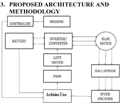
Figure 1: Architecture of Proposed System
This Block diagram of motor speed control and regenerative braking operation as shown in fig 1.The battery source feed to the six step inverter/converter circuit. The three phase AC output of the inverter is used to drive the motor. With the help of Hall sensors the rotor position is detected and the signal that is generated from Hall sensor is given to the controller which energizes appropriate winding of the motor and it starts running. Back E.M.F of BLDC is proportional to motor armature or rotor Speed. The speed can be varied by varying the pulse width of signal (Duty cycle). During running condition motor feed voltage from
battery cell where terminal voltage is less than back E.M.F. That means motor will work as a generator (Regenerative mode) i.e. generated energy supplied to the Battery.
PWM is an effective method for adjusting the amount of power delivered to the load. PWM technique allows smooth speed variation without reducing the starting torque and eliminates harmonics. In PWM method, operating power to the motors is turned on and off to modulate the current to the motor. The ratio of on to off time is called as duty cycle. The duty cycle determines the speed of the motor. The desired speed can be obtained by changing the duty cycle. The Pulse Width Modulation (PWM) in microcontroller is used to control duty cycle of DC motor drive.
[image:4.595.56.253.430.601.2]PWM is an entirely different approach to controlling the speed of a DC motor. Power is supplied to the motor in square wave of constant voltage but varying pulse-width or duty cycle. Duty cycle refers to the percentage of one cycle during which duty cycle of a continuous train of pulses. Since the frequency is held constant while the on-off time is varied, the duty cycle of PWM is determined by the pulse width. Thus the power increases duty cycle in PWM.
Figure 2: Experimental setup of Proposed Electric vehicle system
4.1 Outputs from the PWM Circuit
[image:4.595.314.521.562.732.2]Figure 3 shows the generated PWM signal. Pulse of varying duty cycle (width) is obtained from the PWM circuit. The output has a duty cycle 50%. This is done using a variable resistor (Potentiometer).
4.2 Inverter Output and Motor Speed
Sr. No.
Duty Cycle Inverter o/p
Voltage
Speed (rpm)
1 85% 30.3 V 408
2 70% 27.6 V 370
3 60% 25.2 V 330
4 40% 20.0 V 260
5 30% 17.1 V 200
Table 1: shows the motor speed for different inverter voltage. The frequency of the switching pulse is set at 1.5 KHz. The speed has a proportional relation with the duty cycle or the applied voltage Available Nodes
Figure 4: RPM of the motor versus duty cycle.
Figure 4: illustrates the data relating the pulse width (%) of switching signal with the motor`s speed and shows a proportional relationship, which is certainly expected. The speed is increase with the increment in duty cycle.
4.3 The Energy Regeneration Analysis
Sr. No.
Speed(rpm) Charging
Voltage (V)
(sec)
1 408 12 V 32
2 370 11.3 V 28
3 330 9.4 V 25
4 260 7.7 V 21
5 200 6.3 V 19
Table 2: shows the energy regeneration data for different speeds. The charging Voltage are measured at the terminals of motor. Here, T_br is the time motor takes to become off during normal braking (Sec).
6.CONCLUSION
This paper has proposed a simple but effective method of speed control and braking technique for EV. The proposed work very low initial cost, which is meant to be very economical Energy conservation, plays a major role in these days and the proposed system achieved a breakthrough in conserving energy by eliminating the tradeoff between the energy consumption and efficiency of the smart vehicle. Arduino Uno used in this paper which results in reduction of time and thus giving enhanced time management. The PWM switching is applied only for MOSFET switch of converter hence the switching losses are minimized. The dynamic response of drive is improved and the flexible speed control is achieved. Speed reversal of motor during plugging is overcome using proposed braking technique. In future the proposed drive can also be used with the renewable energy sources for applications like solar pumps, solar powered car, and other solar-wind powered applications.
REFERENCES
[1] N. Pothirasan, Dr. M. Pallikonda Rajasekaran “Regenerative E-Vehicle Using BLDC Motor” International Conference on Emerging Technological Trends [ICETT] 2016 IEEE.
[2] S.M. Baque Billah, Mohammad Jakaria, and Pronab Nath “A Novel Regenerative Braking System of BLDC Motor for Lightweight Electric Vehicles: An Analysis of Braking Characteristics” 2nd International Conference on Electrical & Electronic Engineering (ICEEE), 19-21 December 2017 IEEE, RUET, Rajshahi, Bangladesh.
[3] Pooja Awari, Pankaj Sawarkar, Rupal Agarwal, Anurag Khergade, Sanjay Bodkhe “Speed Control and Electrical Braking of Axial Flux BLDC Motor” 978-1-5090-4874-8/17/$31.00 ©2017 IEEE. [4] Naveen V, T. B. Isha “A Low Cost Speed
Estimation Technique for Closed Loop Control of BLDC Motor Drive” International Conference on circuits Power and Computing Technologies [ICCPCT]2017 IEEE.
[5] P. Sarala, Dr. S. F Kodad, Dr. B. Sarvesh “Analysis of Closed loop Current controlled BLDC Motor Drive” International Conference on Electrical, Electronics, and Optimization Techniques (ICEEOT) – 2016 IEEE.
[6] Yogesh Abhale, Prateek Nigam “Review on Regenerative Braking Methodology in Electric Vehicle” IJAREEIE Vol. 4, Issue 7, July 2015. [7] Ebin Joseph T, Sreethumol M V “Speed Control of
BLDC Motor Drive under Direct Torque Control Scheme with Modified Integrator” ©2015 IEEE. [8] Sagar B Pawar, Nikhil Kumbhar, Seema P Diwan
[image:5.595.56.284.135.243.2] [image:5.595.60.279.307.498.2] [image:5.595.58.284.596.720.2][9] Khushboo Rahim, Mohd. Tanveer, Sandeep Soni, Jagandeep Kaur, Shruti Karkra “Regenerative Braking: Review Paper” International Journal on Recent and Innovation Trends in Computing and Communication ISSN: 2321-8169, Volume: 5 Issue: 5 IJRITCC May 2017.
[10]Rajesh M Pindoriya, S Rajendran, P J Chauhan “Field Programmable Gate Array Based Speed Control of BLDC Motor” 2015.
[11]Aswathi E. R., Prathibha P. K., Jayasri R. Nair “Regenerative Braking of BLDC Motor using Fuzzy Control for Electric Vehicles” IEEE Xplore Compliant - Part Number: CFP18BAC-ART; ISBN:978-1-5386-1974-2 ICICCT 2018.
[12]B. V. Ravi Kumar, K Sivakumar, S. Karunanidhi “A Novel Configuration of Regenerative Braking System to improve the Energy efficiency of an Electric Vehicle with Dual Stator Dual-Rotor BLDC motor” 2017 IEEE Transportation Electrification Conference (ITEC-India)
[13]Azarudeen A, Dolly Mary “Performance Analysis of Conventional and Digital PWM Control Scheme for Speed Control of BLDC Motor Drives” IEEE International Conference on Advances in Electrical Technology for Green Energy 2017.
[14]Ranjan K. Behera, Rustam Kumar, Srirama Murthy Bellala, P. Raviteja “Analysis of Electric Vehicle Stability Effectiveness on Wheel Force with BLDC Motor Drive” IEEE 2018.
[15] Meghana N Gujjar, “Comparative analysis of Field oriented control of BLDC motor using SPWM and SVPWM techniques” 2017 2nd