An Approach of Vibration Control Based on the Design of Three
DOFs Active Vibration Damping Platform
Yi Ye1 and Miaoxian Guo1,*
1
School of Mechanical Engineering, University of Shanghai for Science and Technology, CN-200093, Shanghai, China
Abstract. In this paper, an active vibration control platform is developed for milling processes. In this system, the workpiece is driven by a specially designed active platform to control the relative vibration between the tool and workpiece during milling processes. Numerical simulations are carried out to validate the effectiveness of the control platform. Results indicate that maximum stress of the hinge mechanism of the platform is far less than the yield limit of the material, and the designed platform can meet the use requirements in terms of the maximum displacement and natural frequency.
1 Introduction
Highly accurate miniaturized components are increasing-ly in demand for various industries such as aerospace, electronics, automotive, and so on. Micro-milling is one of main process methods of miniature parts, but because of small cutting area, big load fluctuation and weak rigidity of cutting tool, cutting vibration of micro-milling is more complex than that of common milling. Vibration is an inextricable part of machining process which has detrimental effects on part quality, tool life, and productivity. In extreme situations, it may lead to chatter and destabilize the cutting system.
To overcome the problemsassociated with vibration, researchers have made considerable efforts to control and attenuate vibrations appearing during the cutting process. There are many types of vibration control methods in the machining filed. One of the traditional passive vibration control methods is the machining parameter optimization for the vibration attenuating purpose. However, according to the previous study of Grigoriev et al. machining parameter optimization is not only simply related to vibration, but also influence the machining mechanism, efficiency, etc [1-3]. In other passive method, Duncan et al. introduced the dynamic absorbers to reduce the cutting vibration [4]. Jiang et al. choose a larger tool radius and a smaller cutting depth to control the vibration of curved thin-walled part and, as a result, the curved surface residual stress and deformation have been reduced [5]. Muhammad et al. gave a review of dynamic damping of machining vibration [6]. All the aforementioned studies indicate that the effectiveness is frequency limited and directly related to the dynamic characteristics of the machining system.
Apart from the passive vibration control method, increasing attention have been being paid to the active control of cutting vibration. One way to actively control the cutting vibration in process is the active damping of
machine tool: the control system is designed to add damping at the natural frequencies of control objects so that the damped modes are sufficiently stabilized. For this control type, Ganguli et al. have demonstrated the effect of active damping on regenerative chatter instability for a turning operation [7]. Tewani et al. used a piezoelectric actuator as an active dynamic absorber to suppress chatter in the boring process [8]. Furthermore, Zhang et al. applied the active damping to avoid the chatter in machining process [9]. Chen and Liu presented a novel multi-functional magnetic actuator, which not only damps the vibration of machine tools but also measures the cutting force in real time [10].
the workpiece during the milling processes and improved the rough of surface finish significantly [16].
In previous researches, whatever the vibration's influence on surface and subsurface quality, the vibration process is confined to tradition cutting process, and the frequency components of cutting vibrations to be controlled effectively are limited. In this work, an active vibration control platform with small actuator displacement and high-resonance frequency is presented, to attenuate the relative vibrations between the cutting tool and workpiece. Based on theoretical analysis, a single flexure hinge and the entire hinge platform are modeled. Then the three degrees of freedom (DOF) active workpiece clamping platforms are analyzed by static and dynamic finite element analysis to verify the effective of the active control platform.
2 Active vibration platform design
2.1. Overall design of three DOFs platform
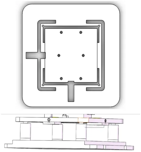
The workpiece holding platform is developed to control the relative vibration between the tool and the workpiece. As showed in Fig. 1, the platform has three degrees of freedom in the x, y and z-directions. It cancels vibration in real time by sensing vibration, then expanding and contracting piezoelectric actuators to filter out the motion.
Fig. 1. Designed three DOFs platform.
Flexure hinges are implemented in platform structure to transform force and displacement generated by actuator to workpiece holder. The flexure hinge works based on the elastic deformation of solid material, and can provide smooth and continuous motion. Therefore, the friction and clearance of the drive system can be negligible. It also provides enough stiffness and load capacity. The material of flexure hinge should have
excellent elasticity and high yield strength. In this study, 65Mn steel is selected. The material properties of 65Mn steel are listed in Table 1.
Table 1. material properties of 65Mn steel. Young’s
modulus (GPa)
Density (kg/m3)
Poisson’s ratio
Yield strength
(MPa)
Tensile strength (MPa)
206 7800 0.3 785 1200
The hinge structure is not completely symmetric but very compact, and when it is subjected to the driving force from the x or y direction, the displacement and deformation generated are relatively similar, and there is no case where the feed in one direction is blocked by the other direction. Moreover, this scheme adds a rod structure, which can generate the effect of lever amplification and increase the stroke of the micro-motion platform.
2.2. Detailed design of three DOFs platform
In the design of flexure hinges, the most important one is the design and calculation of angular stiffness K. Paros and Weisboro presented the original design method and stiffness calculation formula of the flexure hinge. According to relevant literature, the flexure hinge applied to micro-displacement mechanism has two significant features: one is that the displacement and deformation are relatively small; the other is the structure parameter R (notch radius) is smaller than other parameters. According to the characteristics of flexure hinge applied to micro-displacement mechanism, the simplified design method of flexure hinge is deduced. The rotational stiffness of the flexure hinge obtained by this method is given as:
𝐾𝐾𝑎𝑎=2 Ebt5/2
9𝜋𝜋𝑅𝑅1/2 (1)
Where, R is the notch radius, t is the thickness, b is the width of the hinge, and E is the Young's modulus of the flexure material, respectively.
When the piezoelectric actuator pushes the platform, the driving force generates a torque M to the flexure hinge's central axis, which deflects the hinge an angle α around its central axis, which should be of this form:
α=9MπR1/2 2Ebt5/2
(2)
The displacement of the torque M in the feed direction is
𝑦𝑦=9𝜋𝜋𝑅𝑅3/2𝑀𝑀
2Ebt5/2 (3)
relationship between the force and the displacement on the hinge can be expressed as:
𝑃𝑃=𝑘𝑘𝑏𝑏𝑑𝑑 (4)
Where, p is the tension applied to the flexure hinge and d is the stretch distance of the hinge. In addition, the stretch distance of the hinge is
𝑑𝑑=4𝐾𝐾𝛾𝛾𝐿𝐿3𝑃𝑃 𝜃𝜃𝐸𝐸𝐸𝐸
(5)
Where, 𝐾𝐾𝜃𝜃 is the stiffness coefficient, which can be approximately 2.65; γ is the characteristic radius coefficient, which can be approximately 0.8.
Therefore, we can get the angular stiffness is
𝑘𝑘𝑏𝑏=𝑃𝑃𝑑𝑑=4𝐾𝐾𝜃𝜃 EI
𝛾𝛾𝐿𝐿3 (6)
According to the structure of the micro-displacement mechanism, the hinge has a thickness of 8 mm, a width of 4 mm, and a radius of 1.5 mm at the corner.
For the applications of cutting vibration cancelation, actuators with fast response, high stiffness, high resolution, and large output force are required. Two piezoelectric actuators with an external diameter of 10mm, a length of 32mm, a diameter of 4mm, a maximum feed stroke of 30mm and a maximum push force of 500N are selected as driving units for the platform in the horizontal direction. Four piezoelectric actuators, with an external diameter of 20mm, length of 39mm, diameter of push head of 8mm, maximum feed stroke of 30mm and maximum push force of 1500N, are selected as the driving units for the platform in the vertical direction. The actuators are assembled to the stage by using two M3 bolts at the bottom by which the pre-load is provided to prevent the actuators from pulling force. A spherical driving top is designed to prevent the actuator from bending and torque moment.
3 System modelling
The simplified dynamics of machine-tool-workpiece system is schematically presented in Fig. 2. The workpiece is subjected to three inputs: actuator force FA,
cutting force FC, and vibrations of machine tool base VB.
The system output, vibration of workpiece VW is the sum
of the responses to these three inputs. The transfer functions from these inputs to outputs are GA (from FA
to VW), GC (from FC to VW), and GB (from VB to VW) are
given in Eqs. (7)-(9).
where m1, m2, k1, k2, c1 and c2 are modal masses,
stiffnesses and damping of the system, as shown in Fig. 2.
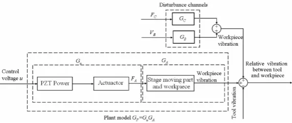
In this work, the moving part of designed platform with workpiece is selected as a control object. It is driven according to the given control signals to cancel the relative vibration between the tool and workpiece. The block diagram of system is shown in Fig. 3. FC and
VB are treated as disturbances. GC and GB are considered
as the transfer functions of disturbance channels correspond to FC and VB, respectively. The vibration of
tool VT is regarded as another disturbance added to the
system. The driving force of actuator FA is regulated by
control input voltage u and Gu, the transfer function
form u to actuator force FA. The plant model Gp for
which the controller synthesis will be carried out equals Gu∙RGA, where GA is measured in the case of actuator
with a static stiffness kA.The parameter model GP of the
controlled object can be obtained by measuring the frequency response function of the system under the
action of broadband input voltage u,then estimating the parameters.
4
Finite element analysis of the platform
Travel distance of the workpiece holding area and the first natural frequency are two key performance parameters. The former one determines the level of vibration can be canceled, and the later should be far away from the teeth pass frequency to avoid the resonance of stage excited by cutting force. In order to avoid the platform manufactured according to the design parameters cannot meet the requirements of use, the hinge mechanism force under the output force of the piezoelectric ceramic, the displacement of the workpiece clamping region and the natural frequency of the platform must be obtained before
the platform is manufactured.
𝐺𝐺𝐴𝐴(𝑠𝑠) = 𝑚𝑚2𝑠𝑠
2+𝑐𝑐 2𝑠𝑠+𝑘𝑘2
𝑚𝑚1𝑚𝑚2𝑠𝑠4+ [𝑚𝑚2𝑐𝑐1+𝑚𝑚1(𝑐𝑐1+𝑐𝑐2)]𝑠𝑠3+ [𝑚𝑚1(𝑘𝑘1+𝑘𝑘2) +𝑚𝑚2𝑘𝑘1+𝑐𝑐1𝑐𝑐2]𝑠𝑠2+ (𝑘𝑘1𝑐𝑐1+𝑘𝑘2𝑐𝑐2)𝑠𝑠+𝑘𝑘1𝑘𝑘2 (7)
𝐺𝐺𝑐𝑐(𝑠𝑠) = 𝑚𝑚2𝑠𝑠
2+ (𝑐𝑐
1+𝑐𝑐2)𝑠𝑠+𝑘𝑘1+𝑘𝑘2
𝑚𝑚1𝑚𝑚2𝑠𝑠4+ [𝑚𝑚2𝑐𝑐1+𝑚𝑚1(𝑐𝑐1+𝑐𝑐2)]𝑠𝑠3+ [𝑚𝑚1(𝑘𝑘1+𝑘𝑘2) +𝑚𝑚2𝑘𝑘1+𝑐𝑐1𝑐𝑐2]𝑠𝑠2+ (𝑘𝑘1𝑐𝑐1+𝑘𝑘2𝑐𝑐2)𝑠𝑠+𝑘𝑘1𝑘𝑘2 (8)
𝐺𝐺𝐵𝐵(𝑠𝑠) = 𝑐𝑐1𝑐𝑐2𝑠𝑠
2+ (𝑘𝑘
2𝑐𝑐1+𝑘𝑘1𝑐𝑐2)𝑠𝑠+𝑘𝑘1𝑘𝑘2
Fig. 2. Simplified model of machine-tool-workpiece system dynamics.
Fig. 3.Block diagram of system.
4.1. Statics analysis of the platform
Through the finite element static analysis of the platform, the maximum stress of the hinge mechanism and the displacement of the workpiece clamping area under the maximum output force of the piezoelectric ceramic can be obtained. In Fig. 4, (a) and (b) show the displacement of the workpiece clamping area of the platform at the maximum output force of the piezoelectric ceramic. It can be seen from the figure that the maximum displacement of the workpiece clamping
region in the x and y directions is 45 μm and 72 μm respectively, which basically meet the design parameters. In Fig. 4, (c) and (d) gives the stress distribution cloud diagram of the hinge. It can be seen from the figure that the maximum stress of the hinge mechanism in the x-direction is 104.3 MPa, which is much smaller than the yield strength of the material (282.7 MPa). And the maximum stress of the hinge mechanism in the y-direction is 146.2MPa, which is still far less than the yield strength of the material. The above analysis shows that the hinge structure can achieve the desired function in both the x and y-directions.
In addition, when a pressure of 1900Pa is applied directly above the platform, the maximum displacement
of the hinge in the z-direction is about 2.3 μm, which is much smaller than the maximum displacement in the vertical direction of the piezoelectric ceramic actuator. And the maximum stress value is 2.16 MPa, which is also
much smaller than the yield strength of the material (282.7 MPa). This indicates that the gravity generated by the fixture has less effect on the displacement in the vertical direction of the platform.
4.2. Modal analysis of the platform
The natural frequency and mode shape of the platform can be obtained by finite modal analysis of the platform. During a stable milling process, the dominant vibration is usually excited by intermittent cutting forces and with a tooth passing frequency (TPF) at
Nz×𝑛𝑛/60 (10)
where Nz is tooth number and n is spindle speed in the
unit of rpm. Since the platform is affected by the cutting force and the output force of the actuator, it is hoped that its first natural frequency can be larger than the excitation frequency of the external force to avoid resonance of the platform. This platform is designed to meet the requirements of applications where the main cutting force frequency is less than 450 Hz. It is equivalent to the tooth-pass frequency of a milling operation with a spindle speed of 9000 rpm using a 3 tooth tool. Fig. 5 shows the modal shape and natural frequency of the platform. It can be seen
from the figure that the first-order natural frequency of the platform is 545 Hz, which can meet the requirements for use under the cutting parameters in the text.
Fig. 4.The displacement and stress of the platform.
fifth-order natural frequency is 1059Hz, which is higher than the cutting vibration frequency of the machine tool.
Fig. 5.Modal analysis of the platform.
4.3. Displacement analysis of the platform
The platform transmits force through the hinge structure to amplify the feed displacement of the piezoelectric ceramic, which requires research and verification whether there is a good linear relationship between the
feed displacement of the micro-platform and the feed displacement of the piezoelectric ceramic. Then, applying different magnitudes of force to the micro-platform, the feed displacement of the platform can be analyzed.
The forces of 500N, 450N, 400N, 350N, 300N, 250N, 200N, 150N, 100N, and 50N are applied to the X and Y directions of the platform respectively, and the displacement deformation in the corresponding direction is calculated by Ansys. After several calculations, the result is shown in Fig. 6 below.
It can be concluded that the magnification of the hinge structure in the X direction is about 1.5 times. In the Y direction, the magnification of the hinge structure is about 2.4 times. Moreover, through the analysis of the image, it can be found that the feed displacement of the two has a good linear relationship.
Fig. 6. Comparison of feed displacement of the platform.
5
Conclusions
The development and application of an active milling vibration control platform that can be used to suppress the relative vibrations between the tool and workpiece during the milling processes is presented. The executing unit of the control platform is a specially designed three DOFs active workpiece holding platform. Through optimized design, the travel distances in the x and
reach up to 450 Hz. It can be seen from the finite element analysis that the maximum stress of the hinge mechanism of the platform is far less than the yield limit of the material, and that the designed platform can meet the use requirements in terms of the maximum displacement and natural frequency.
Although the above numerical simulations were successful, but no actual experimental comparisons have been made. In addition, the active control platform is not very mature, and there are still many deficiencies, and still need improvement. For example, the displacement feeding ratio in different directions is not uniform, which is related to the structural characteristics of the designed hinge. In addition, the active vibration control platform can also increase its stability by adding closed-loop detection. However, due to the limited personal ability and time, this goal cannot be achieved, and the accuracy of the system still has a large room for improvement.
References
1. S.N. Grigoriev, V.K. Starkov, N.A. Gorin, P. Krajnik, J. Kopac, J. Mech. Eng. 60, 213-220 (2014)
2. D. Barrenetxea, J.I. Marquinez, J. Alvarez, R. Fernandez, I. Gallego, J. Madariaga, I. Garitaonaindia, Mach. Sci. Technol. 16, 501-523 (2012)
3. P.J. Pawar, R.V. Rao, J.P. Davim, Mater. Manuf. Process. 25, 424-431 (2010)
4. G.S. Duncan, M.F. Tummond, T.L. Schmitz, Int. J. Mach. Tools Manuf. 45, 497-507 (2005)
5. X.H. Jiang, X.J. Kong, Z.Y. Zhang, Z.P. Wu, Z.S. Ding, M.X. Guo, Int. J. Mech. Sci. 167 (2020)
6. B.B. Muhammad, M. Wan, J. Feng, W.H. Zhang, Int. J. Adv. Manuf. Tech. 89, 2935-2952 (2017)
7. A. Ganguli, A. Deraemaeker, A. Preumont, J. Sound Vibr. 300, 847-862 (2007)
8. S.G. Tewani, K.E. Rouch, B.L. Walcott, Int. J. Mach. Tool. Manu. 35, 91-108 (1995)
9. Y.M. Zhang, N.D. Sims, Smart Mater. Struct. 14, 65-70 (2005)
10. F. Chen, G.Y. Liu, Int. J. Adv Manuf Tech. 89, 691-700 (2017)
11. A.H. El-Sinawi, R. Kashani, J. Mater. Process. Technol. 167, 54-61 (2005)
12. I.T. Al-Zaharnah, J. Mater. Process. Technol. 172, 305-310 (2006)
13. X.Y. Zhang, T. Shinshi, L.C. Li, A. Shimokohbe, Precis. Eng. 27, 273-282 (2003)
14. A. Rashid, C.M. Nicolescu, Int. J. Mach. Tools Manuf. 46, 1626-1636 (2006)
15. C. Brecher, D. Manoharan, U. Ladra, H.G. Kopken, Prod. Eng. 4, 239-245 (2010)
16. X.H. Long, H. Jiang, G. Meng, J. Mater. Process. Tech. 213, 660-670 (2013)