A New Analytical Description and FEA Validation of an Effective
Method to Reduce the Cogging Torque in SM-AFPM Motors
Mohammad R. Alizadeh Pahlavani and Hamid R. Gholinejad Omran*
Abstract—So far, several methods to reduce the cogging torque of permanent magnet motors have been introduced. Implementation and evaluation of these methods have usually been done on radial flux types of motors. Nowadays, as axial flux permanent magnet motors have more advantages over radial ones, they are more attractive. Therefore, in this paper analytical modeling and calculation of the most effective method impact in reducing the cogging torque in axial flux permanent magnet motors will be studied. In fact, in this method the radial edges of the magnets will be curved to have a significant impact on reducing this unwanted component. This paper introduces a new concept to model this method. Finally, the accuracy of the proposed method will be verified by finite element analysis.
1. INTRODUCTION
Nowadays, permanent magnet motors are used increasingly in a wide range of applications. In terms of flux path, these motors are categorized into axial and radial flux types. Axial flux types, also known as disc motors, have higher torque density and efficiency than radial flux types [1]. In these motors, torque ripple is one of the main disadvantages increasing the ripple, due to the interaction between magnets and stator teeth called cogging torque. This additional component in permanent magnet motor torque exists even without the presence of the stator current and creates noise, vibration and undesirable starting performance [2, 3].
One method of cogging torque reduction as reported in [3] is to change the relative position of the poles and group them. This method acts based on creating an asymmetric distribution of the magnetic field in the two sides of the magnets and comes into account as one of the simplest and most economical methods. Pole skewing is another effective method which has been used in various researches having a significant impact on performance [2, 4, 5]. The pole skewing method is more applicable in surface mounted axial flux permanent magnet motors (due to their simple structures). In the interior magnet types the teeth skewing is applied instead of poles skewing. The effect of skewed teeth is like the magnets skewed, but this method has some disadvantages. With this method, increasing the length of the conductors and decreasing their surface cause higher copper losses and then lower efficiency. Also, construction of a stator with skewed teeth is more complex, increasing the cost of applying it. This method is very effective in reducing the cogging torque and improving the distribution of the back EMF [6, 7]. Also other magnet shapes such as triangle, trapezoid and circle are the efficient methods which have been applied to axial flux motors [8]. With the creation of dummy slots, the interaction between magnets and stator slots will be increased, increasing the main frequency, removing some of the harmonic orders and reducing the maximum amount of cogging torque. This method can even cause saturation on teeth surface by changing the distribution of flux lines [6]. Applying changes on the edge of the magnets (similar to other methods related to changes on the poles) has a significant effect on
Received 15 May 2015, Accepted 25 June 2015, Scheduled 6 July 2015
* Corresponding author: Hamid Reza Gholinejad Omran (ff[email protected]).
cogging torque reduction. The [9] is one of the few researches that have discussed this method in which four different modes have been examined on radial flux motors.
Regardless of the influence of each of these methods on cogging torque and their implementation/simulation issues, the analytical study of each method has high importance, too. This work has been done for most of the methods, but modeling of axial flux motors is more difficult due to their unique structures. Mostly, studies on this type of PM motors are then often based on 3D finite element analysis software and not analytical methods. In this paper, using some concepts from existing methods, we have tried to present an analytical method to study the effect of curvature method of poles edges in SM-AFPM motors for the first time. The equations corresponding to this method will be provided firstly. Then, by three-dimensional simulation based on finite element analysis, the accuracy and precision of these relationships is studied.
2. COGGING TORQUE CALCULATION IN AFPM MOTORS
It can be said that many design parameters influence a cogging torque profile, such as slot opening width, dimensions of stator and rotor, air gap length and magnet curve to pole pitch ratio (the magnet embrace). Nevertheless, changing the values of these parameters in order to minimize the cogging torque can change other motor desired characteristics, including cost, volume and efficiency. Therefore, these parameters are considered to be already determined by design specifications unless the cogging torque constraint is also included in the main design procedure. The proposed method in this paper can minimize the cogging torque while not affecting the main design variables of the motor.
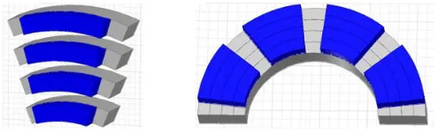
Generally, the AFPM machines are modeled by the quasi three-dimensional computation method introduced in [10]. Based on this computation, these machines are divided into a number of categories as shown in Figure 1. This procedure will give much more accurate results than the average diameter of the rotor [10, 11]. Also, by increasing the number of computational plans, the accuracy and time of the calculation will be increased.
Figure 1. Divided rotor based on quasi 3D method.
According to this approach, a machine will be divided to several machines with different diameters, pole pitch and the proportion of pole arc to pole pitch. After analyzing each of these machines, operational specifications of the main machine can be achieved by summing the results [10].
The modeling of different methods of reducing the cogging torque will be easier with the definition of magnetic flux density distribution produced by the magnets since the change in the shape of the magnets directly affects this parameter. In [12], the air gap flux density distribution without the effect of the slots is given as follows:
BP M(θ) =
∞
n=1,3,5,... −8Br
nπμr ×
sin α p,inπ 2 sinh
2np hm Dav,i
cos (npθ)
μr+ 1
μr sinh
2nphm+g Dav,i
+μr−1
μr sinh
2np−hm+g Dav,i
(1)
where Br and μr are the residual magnetic flux density and permeability of the permanent magnet, respectively. gis the air gap length,hm the magnet height,p the pole pair number, andDav,i the rotor diameter in the ith plan which can be calculated from the following relation [11],
Dav,i=Dout−
(2i−1)
The slotting effect will be applied to the air gap flux density by multiplying Equation (1) by relative permeance function. The relative permeance function is as follow:
λ(θ) =
⎧ ⎨ ⎩
g+lm/μr
0.5πDav,i|θ−θ1|+g+lm/μr (Inside the slots)
1 (Outside the slots)
(3)
where θ1 is the position of the nearest tooth edge from the point where the field is calculated. Now,
with regard to the cogging torque relation in [12], it can be rewritten based on the concepts of quasi method.
Tcog(θ) = S−1
j=0
N
i=1
⎛ ⎜ ⎝
θ+(4j+αs)π/2S
θ+(4j+3αs+1)π/2S
BP M(ϕ)2i 8μ0
Dav,i2 dϕ−
θ+(4j+3αs+1)π/2S
θ+(4j+5αs)π/2S
BP M(ϕ)2i 8μ0
D2av,idϕ
⎞ ⎟
⎠ (4)
In this equation,N is plan number,S the slot number,μ0 the magnetic permeability of free space,
and αs the stator pole-arc to pole-pitch ratio.
3. METHOD EXPLANATION
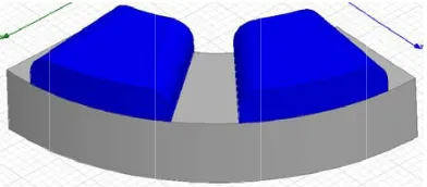
In Figure 2, it is demonstrated how the magnet edges are curved. These curves are created from a quarter of hypothetical circles with the same diameter causing changes in the flux density.
This method can be modeled based on air gap reluctance changes relative to rotor position [9]. In this paper, a new modeling procedure without complex mathematical manipulations will be given. According to the proposed method, in addition to the radial pole division (Figure 1), magnets are divided along the motor axis (Figure 3) leading to ease of modeling.
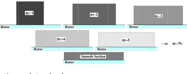
In fact, based on this method, as shown in Figures 4 and 5, the poles are converted to sub poles. These sub poles have different heights and widths. Increasing the number of sub poles will increase the modeling accuracy. In Figure 4,N1 is the number of sub poles.
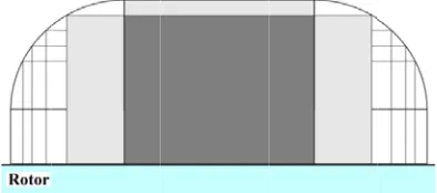
As shown in Figure 5, since the axial divisions must be an approximation of a circle, equal divisions in the vertical axis will not cut off the horizontal axis in equal divisions. For this reason, calculation of the width of each axial division in each plan needs to taken into account of certain considerations, which will be presented in the subsequent sections.
Figure 2. A view of the curvature of the edge of the pole.
Figure 4. Converting a pole to sub-poles.
Figure 5. The sections of a magnet in proposed method.
After dividing the vertical axis in the curved section, the height of each part relative to the smooth surface will be calculated by Equation (5):
Yn1 =
1−(n1−1)
N1
Rc (5)
where Rc is the curve radius. The length of each point on the horizontal axis corresponding to each point on the vertical axis with regard to circle shape of the curve can be calculated by Equation (6):
Xn1 =
R2
c −Yn21 (6)
Using Equations (5) and (6), the width and height of the magnets and the air gap length corresponding to each sub pole in Figure 4 can be obtained. In the ith plan, the sub pole’s width is as follow:
wP M,n1 =αp,i
πDave,i
2p −2 (Rc−Xn1) (7)
The pole arc to pole pitch ratio can be calculated according to Equation (8),
αn1 =
wP M,n1
πDav,i/2p (8)
As mentioned previously, each sub pole has a different height and air gap length, and these two characteristics can be calculated using Equations (9) and (10), respectively:
gn1=g+
(n1−1)
N1
R
c (9)
hmn1=hm−
(n1−1)
N1
R
c (10)
By replacing Equations (8)–(10) into Equation (1), the effect of curvature can be applied. The flux density relationship by taking the effect of curvature of the edges has been brought into Equation (11).
BPM,Curved(θ) = N1+1
n1=1 ∞
n=1,3,5,... −8Br
nπμr ×
sin
α
n1nπ
2
sinh
2nphmn1 Dav,i
cos (npθ)
μr+1
μr sinh
2nphmn1+gn1 Dav,i
+μr−1
μr sinh
2np−hmn1+gn1 Dav,i
Figure 6. An example of duplicate area in calculations (forn1 = 1 andn1 = 2).
A very important point relating to Equation (11) is that some areas of the sub poles such as that shown in Figure 6 will be considered in the calculation several times; of course, the effect of these conflicts must be deleted in the final results of Equation (11).
Equation (12) forn1 from 1 toN1, with the subtraction of the effect of any part by previous part,
eliminates the effect of these conflicts completely.
BPM,Curved(n1)=BPM,Curved,(n1+1)−
maxBP M,Curved,(n1+1)
maxBPM,Curved,(n1)
BPM,Curved,(n1) (12)
4. ANALYTICAL AND FEA RESULTS VALIDATION
At the first stage of this section, a 3-phase motor will be simulated in Ansys-MaxwellR software. Motor nominal output power, voltage and rated speed are taken as 550 W, 120 V and 1500 RPM, respectively. Also, it has 8 poles, 24 slots and a single-layer winding. Pole-arc to pole-pitch ratio is 0.7 in this case. Some other motor characteristics have been tabulated in Table 1.
Analysis of the axial flux permanent magnet motors is only done in 3-D space due to their unique structure. Figure 7 shows a three-dimensional view of the simulated motor in this software.
After completely defining the process of simulation such as applying the mesh, boundaries and material specifications, the cogging torque curve can be calculated for different curvature radii, by finite element analysis. Figure 8 shows the results of calculations for the 2, 4, 6 and 8 mm radii, and the effect of curved edges has been shown clearly in this figure. It is observed that the curved edge with 8 mm radius decreases the torque amplitude by about 85%.
In the performed simulations, the numbers of tetrahedraes for the first case without shaping the magnets and the second case with a curvature of 8 mm are respectively 38207 and 38275 while the simulation times are respectively 1014 sec and 786 sec. Also the rotor is revolving with an angular speed of 1 degree per second; the period of cogging torque is 15 degrees derived using (360◦/24(Slot Number) = 15◦). Therefore, the number of rotor positions considered in one cogging torque
period is 15.
Table 1. Dimensions of motor (in millimeters).
Dimensions Values
Outer Diameter (Stator and Rotor) 120 Inner Diameter (Stator and Rotor) 70
Height of Stator Yoke 25
Height of Rotor Yoke 15
Air Gap Length 1
Slot Opening 2.5
Magnet Length 25
Figure 7. Views of the simulated motor. Figure 8. Cogging torque under the different radius of curvature.
Figure 9. Air gap flux density changes on two poles (analytical).
Figure 10. Air gap flux density changes on two poles (numerical).
Figure 11. Air gap flux density changes on two poles (numerical with analytical).
Due to the significant effect of 8 mm radius, in what follows, the results of analytical and numerical calculations will be confined to this case. For this reason, the air gap flux density corresponding to the case after and before implementing this method based on analytical relationships will be calculated. Figure 9 shows this parameter. The number of axial subdivisions used to model the curved area and the number of radial divisions are 16 and 25, respectively.
To have a more precise and accurate comparison of relationships, flux density curve of finite element analysis (numerical) and analytical relations after implantation method are shown together in Figure 11. As can be seen from Figure 11, it can be argued that using the proposed relationships, curvature of poles edge method can be modeled more accurately.
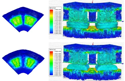
Determination of magnetic flux density distribution in various parts of the motor has great importance because this parameter is very influential on the functional specifications of the machine. For instance, the developed torque is in direct ratio with flux density [2]. Since the curved edges can affect this parameter, the amount and distribution of flux density in two poles of the motor have been shown in 2D and 3D space in Figure 12.
In Figures 13 and 14, the cogging torque curves in smooth and curved edges (with 8 mm radius) have been shown, respectively. For a more accurate comparison, the results of analytical relations and finite element analysis have been drawn together. The accurate amount of the proposed analytical
Figure 12. Flux density distribution in various parts of the motor.
Figure 13. Validation of cogging torque curve before implementing the proposed method.
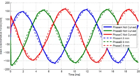
Figure 15. Developed torque curve changes. Figure 16. Back-emf waveform, (after and before implementation of the method).
relations has been determined.
Due to the reduction in the magnets volume in the proposed method, motor operational specifications becomes worse, such as the developed torque and back-emf. According to what was previously stated, the torque value has a direct ratio with the flux density, and since the changes in the flux density distribution are not seen appreciable as seen in Figure 12, the average torque is also not significantly decreased. Figures 15 and 16 show the developed torque and back-emf, respectively. Referring to Figure 15, the aforementioned assumption (negligible reduction in the average torque) is observed. The reduction in torque ripple is clearly visible.
In addition to cogging torque, the improper waveform of back-emf is a factor in creating the torque ripple. Therefore, implementation of a method should not inversely affect the back-emf, and its harmonic distortion should not become worse either. As shown in Figure 16, no negative effect is observed on the back-emf waveform, another benefit of this method.
5. CONCLUSION
In this paper, an effective method to reduce the cogging torque of axial flux permanent magnet motors has been modeled. This method is curvature of the edges of the magnets. This method is modelled based on the idea of converting each pole to several sub poles with different heights, widths and air gap lengths. In order to confirm the validity of the results of the proposed analytical relationships, a three-dimensional finite element simulation has been used. The results represent a reduction of about 85 percent on the cogging torque amplitude and high accuracy of the suggested analytical model. The effect of this method on some other motor characteristics such as the developed torque, flux density and back-emf has also been evaluated in simulations. It is observed that this method has minimum negative effects on motor operational characteristics.
REFERENCES
1. Woolmer, T. J. and M. D. McCulloch, “Axial flux permanent magnet machines: A new topology for high performance applications,”Hybrid Vehicle Conference, IET The Institution of Engineering and Technology, 27–42, 2006.
2. Mahmoudi, A., N. A. Rahim, and H. W. Ping, “Axial-flux permanent-magnet motor design for electric vehicle direct drive using sizing equation and finite element analysis,” Progress In Electromagnetics Research, Vol. 122, 467–496, 2012.
3. Gulec, M. and M. Aydin, “Influence of magnet grouping in reduction of cogging torque for a slotted double-rotor axial-flux PM motor,” International Symposium on Power Electronics, Electrical Drives, Automation and Motion, 812–817, 2012.
5. Aydin, M., Z. Q. Zhu, T. A. Lipo, and D. Howe, “Minimization of cogging torque in axial-flux permanent-magnet machines: Design concepts,” IEEE Transactions on Magnetics, Vol. 43, No. 9, 3614–3622, Sep. 2007.
6. Bianchini, C., F. Immovilli, A. Bellini, and M. Davoli, “Review of design solutions for internal permanent-magnet machines cogging torque reduction,”IEEE Transactions on Magnetics, Vol. 48, No. 10, 2685–2693, 2012.
7. Kudrjavtsev, O. and A. Kilk, “Cogging torque reduction methods,” IEEE Electric Power Quality and Supply Reliability Conference, 251–254, 2014, ISBN 978-1-4799-5020-1.
8. Aydin, M., “Magnet skew in cogging torque minimization of axial gap permanent magnet motors,” Proceedings of the International Conference on Electrical Machines, 1–6, 2008.
9. Chabchoub, M., I. Ben Salah, G. Krebs, R. Neji, and C. Marchand, “PMSM cogging torque reduction: Comparison between different shapes of magnet,” First International Conference on Renewable Energies and Vehicular Tecnology, 206–211, 2012.
10. Parviainen, A., “Design of axial-flux permanent-magnet low-speed machines and performance comparison between radial-flux and axial-flux machines,” Doctoral Thesis, Lappeenranta, Finland, Apr. 19, 2005.
11. Parviainen, A., M. Niemel¨a, and J. Pyrh¨onen, “Modeling of axial flux permanent-magnet machines,”IEEE Transactions on Industry Applications, Vol. 40, No. 5, 1333–1340, 2004.