Radar Cross Section Reduction Property of High Impedance Surface
on a Lossy Dielectric
Vadakkekalathil A. Libi Mol*, Sreekala P. Sasikumar, Dibin M. George, Arimpoorpallan O. Lindo, Neeraj K. Pushkaran, and Chandroth K. Aanandan
Abstract—A detailed study on the performance of a high impedance surface on lossy dielectric is presented in this paper. It is observed that the structure, which is an array of square loops on a grounded dielectric, behaves as artificial magnetic condutor, narrowband absorber or perfect electric conductor depending on the dielectric loss. An equivalent circuit modelling is used to theoretically explain how this transition is happening. The observed narrowband absorption (bandwidth = 0.08 GHz) of the thin (0.016λ) lossy dielectric is scalable to different operating frequencies by varying the structure parameters. The simulation studies on the effect of structural and dielectric properties on the characteristics of this HIS are also dealt with in this paper. Experimental investigation is in good agreement with simulated result and equivalent circuit modelling.
1. INTRODUCTION
Since the pioneering work of high impedance surfaces (HIS) in 1999 by Daniel Sievenpiper [1], it found a lot of applications because of its artificial magnetic conductor (AMC) property at a particular frequency. It consists of frequency selective surfaces (FSS) over a metal backed dielectric substrate. At the resonant frequency, the input impedance of HIS is characterized by very high real part and the imaginary part showing a smooth transition through zero [2]. Thus most of the incident electromagnetic wave is reflected back without any phase reversal resulting in +1 reflection coefficient. Because of this interesting metamaterial property, HIS has found many relevant application in microwaves areas such as radar cross section reduction, low-profile antennas, Fabry-Perot or Leaky wave antennas, EMI/EMC applications, etc.
Radar cross section (RCS) reduction has a lot of applications in different fields especially in military [3, 4]. RCS is a measure of scattered electromagnetic field when the target is illuminated by an incident field, i.e., it measures the detectability of a target. So the RCS reduction reduces the perceptibility and consequently enhance the survivability of the target. There are mainly two common methods used for RCS reduction: applying the radar absorbing material (RAM) on the target or redirecting the scattered wave away from the target by object shaping [5].
RCS reduction by redirecting the scattered wave away from the observer could be realized using a combination of AMC and perfect electric conductor (PEC) in a chess board like configuration [6]. The main disadvantage of this low profile configuration is its narrowband nature. This limitation can be overcome by replacing the PEC cell by another AMC structure operating at different resonant frequency [7].
Radar absorbing material is lossy in nature. One of the commonly used RAM is Salisbury screen [8, 9]. It consists of a resistive sheet having a resistivity close to that of free space (377 Ohm)
Received 16 October 2015, Accepted 31 December 2015, Scheduled 14 January 2016
* Corresponding author: Vadakkekalathil A. Libi Mol (libi.riyaz@gmail.com).
placed roughly one quarter of a wavelength in front of a conducting plate. The disadvantages of this configuration are large thickness and narrow bandwidth. HIS can perform as RAM by the introduction of losses either on FSS or in the dielectric layer. HIS with resistive FSS or FSS with lumped resistor could overcome the drawbacks of Salisbury screen. Li et al. [10] showed that the resistive treble square FSS with thickness 0.193λ could be used for 10 dB RCS reduction for a relative bandwidth of 92.2%. A 10 dB reflectivity reduction for a fractional bandwidth of 126.8% with thickness 0.088λwas realized for a double square loop array with lumped resistors [11]. Triple band HIS absorber with periodic diversified impedance was used for 42% increase in 90% of absorption bandwidth [12]. Two-dimensional array of multiple patches loaded with resistance was proposed for a bandwidth of 76% and thickness of 0.125λ[13].
But the introduction of proper amount of dielectric loss in HIS structures results in their performance as narrowband absorbing material [14]. A cascaded periodic structure on a lossy dielectric was proposed [15] for narrowband RCS reduction, but its equivalent circuit modelling did not consider the lossy component of dielectric impedance. The closed form expressions for analyzing the performance of HIS on a lossy dielectric was done in [2] to analyze the effect of dielectric loss in reflect array antenna performance. Based on this, in our paper, we analyze the performance of square loop FSS elements on a commercially available lossy dielectric substrate using equivalent circuit modelling and reveal the impact of dielectric loss on the input impedance of whole structure: as the dielectric loss increases, the input impedance of HIS decreases. With this variation of input impedance, the HIS performance varies from AMC to RAM and then to PEC. Even though this RAM property is narrowband in nature, it can overcome the drawback of quarter wavelength thickness in Salisbury screen. Also, it is easier to fabricate and has comparable bandwidth as that of multilayered structure in [15].
The paper is organized as follows. In the next section, the structure of FSS under analysis is described. In Section 3, the equivalent circuit modelling and full wave analysis of the structure is described. In Section 4, the experimental set up and validation of absorbing property using equivalent circuit modelling and measurement are described. Section 5 describes the simulation studies on the performance of HIS based on different geometrical and dielectric parameters.
2. GEOMETRY OF THE STRUCTURE
In order to study the performance of HIS on a lossy dielectric as a radar absorbing material, an array of square loop FSS on a grounded dielectric is considered. The structure and its unit cell geometry are shown in Figure 1. The FSS unit cell with dimension 12 mm∗12 mm is considered over a grounded FR4 substrate with thickness 0.8 mm and dielectric constant 4.4−0.11j. Imaginary part of permittivity is included here to impart the losses in the dielectric. The outer and inner dimensions of the square loop is optimized to l = 8 mm and m = 7 mm on the lossless dielectric (r = 0) to obtain the AMC characteristic at 5.81 GHz using CST MW Studio.
(a) (b)
Figure 1. (a) Perspective view of HIS full structure. (b) Geometry of unit cell.
3. FULL WAVE ANALYSIS AND EQUIVALENT CIRCUIT MODELLING
The complex reflection coefficient and impedance of infinite array of square loop FSS on lossy dielectric is obtained by considering a unit cell with appropriate boundary condition by simulation in CST MW Studio. Simulation of the unit cell is done with perfect electric boundaries inY-Z planes and atZMIN,
perfect magnetic boundaries in X-Z planes and an open boundary with de-embedded waveguide port excitation at ZMAX. The unit cell is placed inside a waveguide as shown in Figure 2. The permittivity
(imaginary part) of the substrate is varied to study the characteristics. De-embedding is very important to obtain the impedance and reflection phase just above the structure.
When a wave is incident on the structure, it is reflected or transmitted depending on the impedance mismatch of the structure to free space. For better understanding of the effect of dielectric losses on the impedance of HIS, an equivalent circuit modelling is considered. By applying the loaded transmission line approach for a plane wave excitation, HIS structure can be decomposed into a parallel combination of FSS and grounded dielectric [16, 17], as shown in Figure 3.
Thus HIS impedanceZS depends on both FSS impedanceZF SS and grounded dielectric impedance
ZD as:
ZS = ZF SS∗ZD
ZF SS+ZD (1)
So to calculate impedance of HIS, the impedance values of both grounded dielectric and FSS have to be calculated. The impedance offered by the grounded dielectric for normal incidence is calculated using transmission line model [18, 19].
ZD =j∗ η0∗tan(k0∗h∗
r+jr)
r+jr (2)
where η0 is the characteristic impedance of free space, k0 the free space propagation constant, h the
thickness of the substrate and
r=r−j∗r (3)
By assumingr r, the real and imaginary parts ofZD are given by the following equations:
Re(ZD) = A= η0
r
r
2rtan(k0h
r) −
k0h
r
2r 1 + tan
2(k 0h
r)
(4)
Im(ZD) = B = tan(k0h
r) η 0 r (5)
It can be noted that the real part (A) of ZD is affected by both real part (r) and imaginary part (r) of permittivity whereas the imaginary part (B) depends only on r.
Now, impedanceZF SS is calculated as follows.
The impedance of the free standing metallic square loop array without ohmic loss can be calculated by modelling it as a series LC circuit as shown in Figure 4. The inductance L is due to the current
Figure 3. Loaded transmission line model for plane wave incidence.
(a) (b)
conduction in the loops, which depends on the width of the square loop and periodicity. The capacitance
C is due to the conducting parts of the loop separated by the dielectric material and it depends on the periodicity and gap between the loops. The reactance XL of the inductor and susceptance BC of capacitor given in [20, 21] are repeated here for completeness.
XL η =
l
d F(d,2s, λ) (6)
BC ∗Z0 = 4
l
dF(d, g, λ) (7)
where
F(p, w, λ) = p
λ∗Cosθ
ln
Cosec·π∗w 2p
+G(p, w, λ)
(8)
Here G is the correction term [20], g the gap between the loops, s the width of the loop, l the outer dimension of the loop, anddthe periodicity.
To obtain the capacitance of lossy dielectric loaded square loop FSS, the unloaded capacitance (free standing) has to be multiplied by effective permittivity of surrounding dielectric. As the FSS is loaded in between two dielectrics (free space and substrate), the effective permittivity (eff) can be approximated by the average of the permittivity values [2, 22–24] given by the following expression:
eff = r+ 1
2 =
r+ 1
2 −j∗
r
2 (9)
The real (R) and imaginary part (X) ofZF SS is determined using formulas given in [2], by considering this series LC circuit. The loss component of FSS impedance due to the lossy dielectric is represented by the resistive componentR.
ZF SS =R+jX = 1−ω
2LC
eff
jω∗Ceff (10)
Using Equations (4), (5) and (10), the overall HIS impedance ‘ZS’ [2] can be expressed as follows.
Re(ZS) = (AR−BX)(A+R) + (BR−XA)(B+X)
(A+R)2+ (B+X)2 (11)
Im(ZS) = X(A
2+BX) +B(R2+BX)
(A+R)2+ (B+X)2 (12)
whereAand R are the real parts, andB and X are the imaginary parts of ZD andZF SS, respectively. The reflection coefficient of this periodic structure for a plane wave excitation can be expressed as:
Γ = ZS−η0
ZS+η0
. (13)
This implies that when the real part of the impedance of the periodic structure is much larger than that of free space, it will give reflection coefficient magnitude as ‘1’ and phase as ‘0◦’, i.e., the structure act as AMC and the imaginary part of impedance has a smooth transition through zero [2] due to the cancellation of imaginary part of impedance of FSS and dielectric. As the impedance of structure approaches that of free space, reflection coefficient approaches zero resulting in very good absorption, i.e., structure act as radar absorbing material. As the structural impedance become much less than that of free space, reflection coefficient magnitude and phase become ‘1’ and ‘180◦’ respectively, i.e., the structure displays PEC performance.
4. EXPERIMENTAL SETUP AND VERIFICATION
the structure the receiving horn antenna is moved on the arch around the structure. The transmitting antenna is also rotated to study the scattering characteristic with respect to incident angle.
For this measurement 24×24 unit cell square loop array is fabricated on a 30×30 cm metal backed FR4 dielectric substrate (r = 4.4 andr = 0.11,h= 0.8 mm) as shown in Figure 5(b). The transmitting antenna is set for normal incidence. The receiving antenna is placed near the transmitting antenna to measure the normally reflected wave. The reflectivity from a metal plate with same dimension as of the structure is also taken for normalization. Reflection coefficient value of −30.6 dB at 5.88 GHz is obtained as in Figure 6. This result is compared with that obtained from CST simulation and equivalent circuit modelling done using MATLAB. The simulation gives the reflection coefficient of −25.5 dB at 5.81 GHz, while the equivalent circuit modelling gives a peak of −22 dB at 5.81 GHz. The difference between measured and simulated results is due to fabrication error and tolerance in the value of dielectric constant of the commercially available substrate. This has been verified by simulation by varying the parameters.
This observed reduction in RCS can be due to the scattering of the wave away from observer or by absorption. So to prove the absorbing property of our lossy HIS, the distribution of scattered power around the structure at 5.88 GHz is measured and shown in Figure 7. The incident angle is set as 0◦, 10◦ and 30◦, respectively, and the receiving antenna is moved around. For the metal plate, for angles of incidence 0◦, 10◦ and 30◦, most of the incident power reflects back to 0◦,−10◦ and −30◦, respectively. For 0◦ angle of incidence, the HIS structure also shows maximum reflectivity at zero reflection angle, which is 30 dB less than that of metal plate, and the scattered power in all other directions is very small. This indicates that most of the incident power is absorbed. For other angles of incidence, this absorption property is also verified as in Figures 7(b) and (c).
(a) (b)
Figure 5. (a) Measurement set up. (b) Fabricated structure.
Figure 6. Reflection characteristics of the structure under normal incidence.
(a) (b) (c)
(a) (b)
(c) (d)
Figure 8. Simulation Results by varying the loss in the dielectric. (a) Real part of impedance. (b) Imaginary part of impedance. (c) Reflection coefficient magnitude. (d) Reflection phase.
5. SIMULATION RESULTS AND DISCUSSIONS
In this section, we will discuss the impact of different FSS and substrate parameters such as dielectric loss, thickness of dielectric, angle of incidence, polarization, periodicity and width of the square loop on the performance of HIS.
5.1. Effect of Dielectric Loss (r)
The loss in the dielectric is the key factor in determining the performance of HIS as AMC, RAM or PEC. To study the effect, the imaginary part of permittivity (r) of the substrate is varied from 0 to 0.22, as shown in Figure 8. r = 0 corresponds to the lossless substrate, and the increase in value corresponds to an increase in loss.
Whenr = 0,the real part of impedance is very high (3000 ohms) compared to free space, thus the reflection coefficient magnitude is 1. The phase varies from +180◦ to−180◦ with 0◦ reflection phase at 5.81 GHz. It is also observed that the imaginary part of impedance shows a smooth transition through zero at this frequency, which is due to the cancellation of imaginary parts of impedance of grounded dielectric and FSS. Whenr = 0.11 (tanδ = 0.025), the real part of impedance is decreased to free space impedance, thus the maximum absorption is obtained. The reflection phase shows a drastic transition at this frequency. Further increase in loss component results in reduction in impedance to zero, causing the structure to act as a perfect metal plate. Hence it can be concluded that the loss in the substrate can be adjusted to obtain maximum absorption. It is also noted that there is only a slight variation in the resonant frequency, whiler is varied.
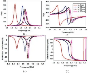
5.2. Effect of Thickness of Dielectric (h)
(a) (b)
(c) (d)
Figure 9. Simulation results for different dielectric thickness (h). (a) Real part of impedance. (b) Imaginary part of impedance. (c) Reflection coefficient magnitude. (d) Reflection phase.
phase shows a drastic transition from +180◦ to −180◦ at this frequency. Further increase in thickness results in an increase in impedance to 1150 ohms, which is very high compared to free space impedance and results in AMC characteristics at 5.79 GHz. It is also noted that with the increase in thickness from 0.2 mm to 1.6 mm, the resonant frequency decreases from 5.81 GHz to 5.79 GHz.
5.3. Effect of Angle of Incidence and Polarization
The effect of angle of incidence and polarization on the absorbing property of the structure is also studied. The incident angle is set as 0◦, 30◦, 60◦ and 80◦, respectively. The comparison of TE and TM polarized plane wave incidences is shown in Figure 10. For the TE polarized wave, the absorbing peak is shifted to high frequency with the increase in angle of incidence. It is also observed that the structure loses the absorption property when the angle of incidence is greater than 45◦. For the TM polarized wave, the absorbing frequency remains constant for angle of incidence up to 60◦, and it loses its property for higher angle of incidence. The absorbing property of TM and TE polarized waves shows that it has good polarization stability for small incident angles.
5.4. Effect of Periodicity (d)
Figure 10. Reflection characteristics with respect to polarization and angle of incidence.
(a) (b)
(c) (d)
Figure 11. Simulation results showing the effect of periodicity (d) on (a) Real part of impedance. (b) Imaginary part of impedance. (c) Reflection coefficient magnitude and (d) Reflection phase.
an increase in periodicity, as given by Equation (7). It is also noted that the resonant frequency, which is inversely proportional to capacitance C, increases with increase in periodicity.
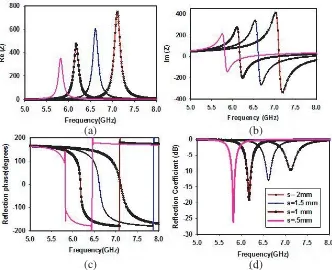
5.5. Effect of Width of Square Loop (s)
(a) (b)
(c) (d)
Figure 12. Simulation result showing the (a) Real part of impedance. (b) Imaginary part of impedance. (c) Reflection phase and (d) Reflection coefficient magnitude with respect to the width of the square loop (s).
performance is deteriorated. The reflection phase shows a zero point at this frequency. The shift in frequency can be explained by using equivalent circuit modelling. When the width of the square loop increases, the inductance L of the FSS decreases (Equation (6)). As the resonant frequency of HIS is inversely proportional to inductance, it increases with increase in the width of the square loop.
6. CONCLUSION
The radar cross section reduction property of high impedance surface on a lossy dielectric is analyzed in this work. The equivalent circuit modelling is done to explain this AMC-RAM-PEC transition property. The observed and experimentally verified narrowband RAM property of periodic structure on the thin lossy dielectric can be utilized for designing narrowband thin planar absorber over commercially available lossy dielectric. It is concluded that while studying the performance of HIS, the effect of losses in the dielectric must be taken into consideration because this loss can contribute to AMC, RAM or PEC characteristic of the periodic structure.
ACKNOWLEDGMENT
Authors would like to acknowledge the financial and infrastructural support from UGC and DST, Government of India.
REFERENCES
1. Sievenpiper, D., L. Zhang, R. F. J Broas, N. G. Alexopolous, and E. Yaablonovicth, “High impedance electromagnetic surfaces in a forbidden frequency band,”IEEE Trans. Microw. Theory Tech., Vol. 47, No. 11, 2059–2074, Nov. 1999.
3. Lee, K.-C., C.-W. Huang, and M.-C. Fang, “Radar target recognition by projected features of frequency-diversity RCS,”Progress In Electromagnetics Research, Vol. 81, 121–133, 2008.
4. Li, N.-J., C.-F. Hu, L.-X. Zhang, and J.-D. Xu, “Overview of RCS extrapolation techniques to aircraft targets,” Progress In Electromagnetics Research B, Vol. 9, 249–262, 2008.
5. Knott, E. F., M. T. Tuley, and J. F. Shaeffer,Radar Cross Section, 2nd Edition, SciTech Publishing, Inc., Raleigh, NC, USA, 2004.
6. Paquay, M., J.-C. Iriarte, I. Ederra, R. Gonzalo, and P. de Maagt, “Thin AMC structure for radar cross-section reduction,”IEE Tran. Antennas and Prop., Vol. 55, No. 12, 3630–3638, 2007. 7. De Cos, M. E., Y. Alvarez-Lopez, and F. Las-Heras Andres, “A novel approach for RCS reduction
using a combination of artificial magnetic conductors,” Progress In Electromagnetics Research, Vol. 107, 147–159, 2010.
8. Salisbury, W. W., “Absorbent body for electromagnetic waves,” U.S. Patent 2 599 944, Jun. 10, 1952.
9. Fante, R. L. and M. T. McCormack, “Reflection properties of the salisbury screen,” IEEE Trans. Antennas Propag., Vol. 36, No. 10, 1443–1454, Oct. 1988.
10. Li, M., S. Q. Xiao, Y.-Y. Bai, and B.-Z. Wang, “An ultrathin and broadband radar absorber using resistive FSS,”IEEE Antennas and Propagation Letters, Vol. 11, 748–751, 2012.
11. Shang, Y., Z. Shen, and S. Xiao, “On the design of single-layer circuit analog absorber using double-square-loop array,” IEEE Trans. Antennas Propag., Vol. 61, No. 12, 6022–6029, Dec. 2013. 12. Zhang, G. R., P. H. Zhou, H. B. Zhang, L. B. Zhang, J. L. Xie, and L. J. Deng, “Analysis and design of triple-band high-impedance surface absorber with periodic diversified impedance,” J. Appl. Phys., Vol. 114, 164103, 2013.
13. Tang, W. and Z. Shen, “Simple design of thin and wideband circuit analogue absorber,”Electron. Lett., Vol. 43, No. 12, 689–691, Jun. 2007.
14. Costa, F. and A. Monorchio, “Electromagnetic absorbers on high impedance surfaces: From ultra narrowband to ultra wideband absorption,”Advanced Electromagnetics, Vol. 1, No. 3, 7, Oct. 2012. 15. Sujatha, M. N. and K. J. Vinoy, “Analysis of absorption characteristics of stacked patch arrays on
moderately lossy dielectric layers,” Appl. Phys. A, Vol. 119, 1143–1148, 2015.
16. Yang, F. and Y. Rahmat-Samii, Electromagnetic Band Gap Structures in Antenna Engineering, Cambridge University Press, 2009.
17. Simovski, C. R., P. Maagt, and I. V. Melchakova, “High impedance surfaces having resonance with respect to polarization and incident angle,”IEEE Trans. Antennas Propaga., Vol. 53, No. 3, 908–914, 2005.
18. Hashemi, S. M., S. A. Tretyakov, M. Soleimani, and C. R. Simovski, “Dual-polarized angularly stable high-impedance surface,”IEEE Trans. Antennas Propaga., Vol. 61, No. 8, 4101–4108, 2013. 19. Tretyakov, S., Analytical Modeling in Applied Electromagnetics, Artech House, Norwood, MA,
USA, 2003.
20. Marcuvitz, N.,Waveguide Hand Book, McGraw Hill, New York, 1951.
21. Langley, R. J. and E. A. Parker, “Equivalent circuit model for arrays of square loops,”IET Electron. Lett., Vol. 18, No. 7, 294–296, 1982.
22. Costa, F., A. Monorchio, and G. Manara, “Efficient analysis of frequency selective surfaces by a simple equivalent circuit approach,”IEEE Antennas and Propag. Mag., Vol. 54, No. 4, 35–48, 2012. 23. Costa, F., A. Monorchio, and G. Manara, “An equivalent-circuit modelling of high impedance surfaces employing arbitrarily shaped FSS,” Proc. Int. Conf. on Electromagnetics in Advanced Applications, ICEEA, 852–855, Turin, Sep. 14–18, 2009.