Performance Analysis of MIMO Channel Under Distributed
Orthogonal Spaces
B. Yamini Keerthi
1,P. Poorna Priya
21
Mtech student, Dept. Of Electronics and Communication, Dadi Institute of Engineering and Technology, Vizag, Andhra Pradesh, India.
2
Assistant Professor, Dept. Of Electronics and Communication, Dadi Institute of Engineering and Technology, Vizag,Andhrapradesh,India.
[email protected] [email protected]
ABSTRACT
The main aim of this paper to analyze the performance analysis of the system which uses space-time turbo codes under Distributed Orthogonal Spaces which are combined with adaptive beam forming for multiple transmitter and receiver antennas based on distributed orthogonal frequency division multiplexing (OFDM) system. The performance analysis has been implemented using maximum-likelihood detection and simulation results demonstrate that the proposed system not only provides the good interfacing and also improves the bit-error rate (BER) performance of the system. Experimental results show that an adaptive beamforming gives the optimum performance on relay fading channels and BPSK recovery. In this system we optimize the fading channel and give the comparative analysis of 2*2, 4*4 and 16 *16 BER analysis.
KEY WORDS
MIMO, OFDM, BER, Q-PSK, WiMAX, QAM Modulation
INTRODUCTION
The first WiMAX system is based on the IEEE 802.16- 2004 standard. The features to support mobile applications were added in December, 2005 to introduce 802.16-2005. The resulting standard is referred to as mobile WiMAX. The mobile WiMAX system provides a large number of flexibility in terms of deployment options and potential applications. IEEE 802.16 is a promising technology for ensuring broadband access for the last mile connectivity. It provides a wireless backhaul network that enables high speed Internet access to residential, small and medium business customers, as well as Internet at a cost effective, rapidly deployable solution access for Wi-Fi hot spots and cellular base stations. PHY layer of mobile WiMAX has scalable FFT size from 128 to 2048 point FFT and the range is from 1.6 to 5 Km at 5MHz. Further, MIMO wireless systems help to achieve the goals of the future generation wireless communication system in terms of high data rate, high performance and optimum utilization of the bandwidth. The incorporation of MIMO in mobile WiMAX significantly improves the system coverage, quality of the signal and reliability against fading conditions.
The WiMAX physical layer model is based on OFDM (Orthogonal Frequency Division Multiplexing) technique. OFDM is the transmission scheme to enable high-speed data, video and multimedia communications which is used by various commercial broadband systems. OFDM is an elegant and efficient scheme for high data rate transmission in a non-line-of-sight radio environment. The physical layer model of WiMAX system is shown in figure 1. The various blocks of this model are explained below
1.1 Randomization: It is the first process which is carried out in the WiMAX Physical layer after the data packet is received from the higher layers and each of the burst in Downlink as well as in the Uplink is randomized. It is basically scrambling of data to generate random sequence in order to improve coding performance and data integrity of the input bits.
1.2 Forward Error Correction (FEC): It basically deals with the detection and correction of errors due to path loss and fading that leads to distortion in the signal. There are number of coding systems that are involved in the FEC process like RS codes, convolution codes, Turbo codes, etc. Basically we will be focusing upon the RS as well as the convolution codes.
1.2.1 RS code:
These are non-binary cyclic codes that add redundancy to
the data. This redundancy is basically addition of parity bits into the input bit stream that improves the block errors.
1.2.2 Convolution codes (CC):
Available online: https://edupediapublications.org/journals/index.php/IJR/ P a g e | 5742 uses Convolution code as the mandatory FEC.
Fig. 1 WiMAX OFDM physical layer model
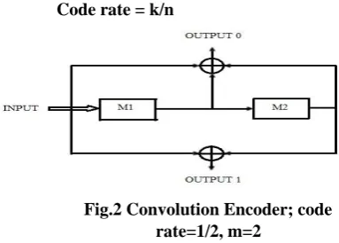
These convolution codes are used to correct the random errors and are easy to implement than RS codes. Coding rate is defined as the ratio of the input bits to the output bits. Higher rates like 2/3 and 3/4, are derived from it by employing “puncturing.” Puncturing is a procedure that involves omitting of some of the encoded bits in the transmitter thus reducing the number of transmitted bits and hence increasing the coding rate of the CC code and inserting a dummy “zero” metric into the convolution Viterbi decoder on the receive side of WiMAX Physical layer in place of the omitted bits. Code rate of convolution encoder is given as:-
Code rate = k/n
Fig.2 Convolution Encoder; code rate=1/2, m=2
For Decoding the Viterbi algorithm is used at the receiver side of the PHY layer. To describe a convolution code, one need to characterize the encoding function (m), so that given an input sequence m, one can readily compute the output sequence U.
1.3 Interleaving:
It aims at distributing transmitted bits in time or frequency domain or both to achieve desirable bit error distribution after the demodulation process. In interleaving, data is mapped onto non-adjacent subcarriers to overcome the effects of multipath distortion and burst errors. Block
interleaving mainly operates on one of the block of bits at a time.
The number of bits in each block is known as interleaving depth, which defines the delay introduced by interleaving process at the transmitter side. A block interleaving can be described as a matrix to which data is written in column format and data is read in row wise format, or vice versa.
1.4 Modulation:
This process involves mapping of digital information onto analog form such that it can be transmitted over the channel. A modulator is involved in every digital communication system that performs the task of modulation. Modulation can be done by changing the amplitude, phase, as well as the frequency of a sinusoidal carrier. In this paper we are concerned with the digital modulation techniques. Various digital modulation techniques can be used for data transmission, such as M-PSK and M-QAM, where M is the number of constellation points in the constellation diagram. Inverse process of modulation called demodulation is done at the receiver side to recover the original transmitted digital information.
1.5 Pilot Insertion:
Used for channel estimation & synchronization purpose. In this step, pilot carriers are inserted whose magnitude and phase is known to the receiver
1.6 Inverse Fast Fourier Transform (IFFT):
An Inverse Fast Fourier transform converts the input data stream from frequency domain to time domain representing OFDM Subcarrier as the channel is basically in time domain. IFFT is useful for OFDM system as it generates samples of a waveform with frequency components satisfying the orthogonally condition such that no interference occurs in the subcarriers.
Similarly FFT converts the time domain to frequency domain as basically we have to work in frequency domain. By calculating the outputs simultaneously and taking advantage of the cyclic properties of the multipliers FFT techniques reduce the number of computations to the order of N log N. The FFT is most efficient when N is a power of two.
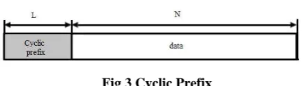
Cyclic Prefix
Fig 3 Cyclic Prefix Communication channels:
Communication channels are kind of medium of communication between transmitter and receiver. These channels are mainly divided into fast and slow fading channels. A channel is known as fast fading if the impulse response of the channel changes approximately at the symbol rate of the communication system, whereas in slow fading channel, impulse response stays unchanged for several symbols
1.7 WiMAX-MIMO SYSTEMS
MIMO systems created according to the IEEE 802.16-2005 standard (WiMAX) under different fading channels can be implemented to get the benefits of both the MIMO and WiMAX technologies. Main aim of combining both WiMAX and Spatial multiplexing MIMO technique is to achieve higher data rates by lowering the BER and improving the SNR of the whole system. The proposed block diagram of WiMAX-MIMO systems is given in figure 4.
Fig. 4 WiMAX-MIMO SYSTEM
Fig. 5 MIMO-mobile WiMAX mode
The use of WiMAX technology with the MIMO technology provides an attractive solution for future broadband wireless systems that require reliable, efficient and high-rate data transmission. Employing MIMO systems in WiMAX [18] yields better BER performance compared to simple WiMAX protocol. Spatial multiplexing technique of MIMO systems provides spatial multiplexing gain that has a major impact on the introduction of MIMO technology in wireless systems thus improving the capacity of the system.
Combining of both the systems involves employing STBC encoder and decoder at the transmitter and receiver side of WiMAX Physical Layer respectively.
1.8 Channel
Additive White Gaussian Noise (AWGN) AWGN is a channel model in which the only impairment to communication is a linear addition of wideband or white noise with a constant spectral density expressed as watts per hertz of bandwidth and a Gaussian distribution of amplitude. The model does not account for fading, frequency selectivity, interference, nonlinearity or dispersion. In the study of communication systems, the classical (ideal) AWGN channel, with statistically independent Gaussian noise samples corrupting data samples free of inter-symbol interference (ISI), is the usual starting point for understanding basic performance relationships. An AWGN channel adds white Gaussian noise in the signal that passes through it.
1.9 SPACE TIME CODES:
Alamouti Space-Time Code:
Space-time block codes (STBC) are a generalized version of Alamouti scheme but have the same key features. These codes are orthogonal and can achieve full transmit diversity specified by the number of transmit antennas. In other words, space-time block codes are a complex version of Alamouti’s space-time code, where the encoding and decoding schemes are the same as there in the Alamouti space-time code on both the transmitter and receiver sides. The data are constructed as a matrix which has its columns equal to the number of the transmit antennas and its rows equal to the number of the time slots required to transmit the data. At the receiver side, the signals received are first combined and then sent to the maximum likelihood detector where the decision rules are applied.
Available online: https://edupediapublications.org/journals/index.php/IJR/ P a g e | 5744 needed in order to obtain a reliable MIMO channel estimate.
Because of the computation complexity of blind and semi-blind methods, many wireless communication systems still use pilot sequences to estimate the channel parameters at the receiver side.
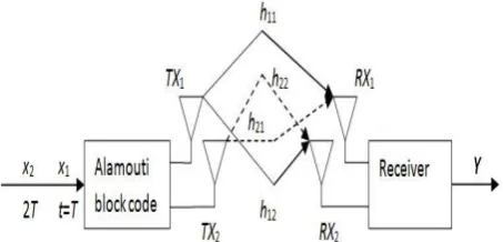
It is a complex space-time diversity technique that can be used in 2×1 MISO mode or in a 2×2 MIMO mode. The Alamouti block code is the only complex block code that has a data rate of 1 while achieving maximum diversity gain. Such performance is achieved using the following space-time block code:
Fig 6: Alamouti space-time diversity technique
Briefly, two antennas are used, to send two OFDM symbols and their conjugate, in two time slots, which brings a diversity gain without having to compromise on the data rate. Over the air, the transmitted symbols will suffer from channel fading and at the receiver, their sum will be received. Here is the schematic diagram of an Alamouti wireless system in 2×2 MIMOmode
Fig 7: A 2×2 MIMO Wireless System Using the Alamouti Block Code
Since the transmission is done over two periods of time, the decoding will also be done over two periods of time. At the receiver, the received vector Y can be represented by the following equation:
This is for the first time period. For the second time period, the equation is as follows:
where represents the received OFDM symbol at the first time period, for antennas 1 and 2, respectively,
and where represents the received OFDM symbol at the second time period for antennas 1 and 2, respectively. Both equations can easily be combined and arranged to produce the following result:
The next step is to find a way to isolate the transmitted symbols, x1and x2. One way to reduce the number of
Available online: https://edupediapublications.org/journals/index.php/IJR/ P a g e | 5745 We can isolate x1and x2by simply multiplying
the matrix Y by the inverse of H. However, since this matrix is not square, we need to use the Moore-Penrose pseudo-inverse H+ to solve our equations:
Using this inverse matrix expression, the noisy estimated transmitted symbols can be found using the following expression:
The last step would be to make a final decision on the transmitted symbols. In Nutaq’s OFDM reference design, the decision is made based on the minimum squared Euclidian distance criterion. In the next figure, we can see that the addition of diversity to the system brings a significant performance gain in terms of BER in simulation:
Proposed Method
Orthogonal space-time codes
The Alamouti space-time code supports maximum-likelihood (ML) detection with linear processing at the receiver. The simple structure and linear detection of that code makes it very attractive; it has been adopted for both the W-CDMA and CDMA- 2000 standards. That scheme was later generalized in to an arbitrary number of antennas. Here, they will brief review the basics of STBCs. Figure 3.3 shows the baseband representation for Alamouti STBC with two antennas at the transmitter. The input symbols to the space-time block encoder are divided into groups of two symbols each. At a given symbol period, the
two symbols in each group {c1,c2} are transmitted
simultaneously from the two antennas. The signal transmitted from Antenna 1 is c1and the signal
transmitted from Antenna 2 is c2. In the next symbol
period, the signal -c*
2 is transmitted from Antenna 1
and the signal c*
1 is transmitted from Antenna 2. They
assume a single-antenna receiver, and denote with h1 and h2 be the channels from the and second transmit antennas to the receive antenna, (Figure 3.4) respectively. The channel gains are constant over two consecutive symbol periods. The received signals can be expressed as
Fig 8: Transmitter Diversity With Orthogonal Space-Time Block Coding
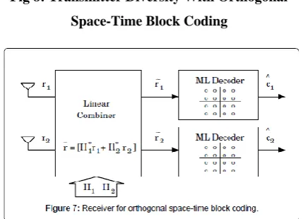
Fig 9: Receiver For Orthogonal Space-Time Blocks Coding
D
Available online: https://edupediapublications.org/journals/index.php/IJR/ P a g e | 5746 define the received signal vector the code
symbol vector , and the noise
vector . The above Equations can be rewritten in a matrix form as
r = Hc + n
The matrix H represents a concatenation of the channel vector (h1 h 2) t and the Alamouti code. The vector n is a complex Gaussian random vector with zero mean and covariance No = 2. Let us define C as the set of all possible symbol pairs c = {c1,c2 }.
Diversity order provided by that scheme is 2Lr. Figure 3.4 shows a simplified block diagram for the receiver with two receive antennas. Note that the decision rule in (2.12) and (2.14) amounts to performing a hard decision
on respectively. Therefore, as
shown in Figure 5, the received vector after linear combining, RM, can be considered as a soft decision for c1 and c2, which can be utilized by any outer
channel codes used in the system. Note also that for the above 4×4 STBC, the transmission rate is one symbol/transmission, and it achieves the maximum diversity order of 4 that is possible with a 16×16 system. The method of Alamouti can be generalized to more than two transmit antennas. The resulting orthogonal codes are still optimally decoded with a linear receiver. Unfortunately, only a few codes with a rate of one symbol/ transmission are available, and for the case of general complex-valued signals, there is no orthogonal rate-1 code beyond the Alamouti code. However, it is possible to design orthogonal codes by relaxing the rate requirement below one symbol/ transmission. For example, for Lt=4, a rate 1/2 STBC
is given by
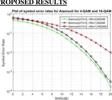
PROPOSED RESULTS
Fig 10: BER of Alamouti Codes Based on QAM Modulation
Fig 11: BER of Alamouti And MRC With 2×1 And 1×2
Available online: https://edupediapublications.org/journals/index.php/IJR/ P a g e | 5747 Fig 13: BER of Alamouti, OSTBC and
MRC with 2x2,4x1 and 1x4
From the above experimental results, we can say that our proposed schemes better performance in terms of BER compared to existing methods.
Table 1: BER performance Proposed and Existing Methods at SNR = 8db
The MIMO-WiMAX model is simulated for different digital modulation schemes (BPSK, QPSK, QAM) with the consideration of ½, ¾ code rates of convolutional codes under AWGN, Rayleigh and Rician channels with the help of MATLAB package. The performance parameter in terms of BER of MIMO-WIMAX systems is determined and compared for adaptive modulation and various constant modulations. The simulation is carried out at 5 MHz channel bandwidth for the physical layer of MIMO-WIMAX at both the transmitter and the receiver. The simulation parameters used for simulation is given in Table 2.
Table 2 Simulations Parameters for different channels
STANDARD 802.16e CHANNEL MODEL
AWGN, Rayleigh, Rician
MODULATION SCHEME BPSK, QPSK, 16 & 64 QAM
CONVOLUTION CODE RATE
1/2, ¾
CYCLIC PREFIX 1/8
BANDWIDTH 5 MHz
LENGTH OF FFT 512
SNR 0-25
Fig 14 BER of MIMO-WiMAX system for different modulation in AWGN channel
Fig. 14 shows BER vs. SNR performance analysis of BPSK, QPSK and 64-QAM modulation technique over Additive White Gaussian Noise channel. BPSK has lower BER than QPSK and 64 QAM. For ex. at SNR=6, BER in BPSK is 0.0025 where QPSK is 0.020 & 64QAM is around 0.4. At SNR=15 BPSK BER=10 -6 but QPSK BER 10-4 and 64 QAM-BER 10-3.
Table 3 Comparison of SNR BPSK(BER) of 16QAM for 6 and 15 Rounds
Method Bit-Error Rate
No-Diversity 0. 1159
MRC 0. 2218
OSTBC (4×1) 0. 0037
Available online: https://edupediapublications.org/journals/index.php/IJR/ P a g e | 5748 Fig 15 BER of MIMO-WiMAX system for
different modulation with in Rayleigh Fading channel
Fig 15 shows performance analysis of BPSK, QPSK and 64-QAM modulation technique over Rayleigh fading Channel. In graph as the value of SNR is increases, BER is a decrease in all three-modulation technique. BER performance of BPSK is much better than QPSK and 64 QAM. Also, QPSK is better than 64-QAM for higher SNR values.
Table 4 Comparison of SNR QPSK(BER) of 16QAM for 6 ,15 ,21 and 25 Rounds
Fig 16 BER of MIMO-WiMAX system for different modulation with in Rician channel
Fig. 16 shows performance analysis of BPSK, QPSK and 64-QAM modulation technique over Rician fading channel. In graph as the value of SNR is increases, BER is decreases in all three-modulation technique is shown in Table 4.5, that mean for better performance BPSK may preferred. There is a little difference exists in BER performance of MIMO WiMAX system between QPSK and BPSK modulation schemes.
Available online: https://edupediapublications.org/journals/index.php/IJR/ P a g e | 5749
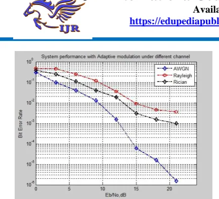
Fig 17 BER of MIMO-WiMAX system for different modulation with in Rician channel
Table 6. Comparison of Adaptive modulation in different channel.
Fig 17 shows under AWGN channel, the BER has a value near 10-6 at Eb/No of 21dB. While in Rician
channel, the MIMO-WiMAX model achieves BER performance of about 10-3 at Eb/No of 21dB. This BER
is worse in Rayleigh channel when compared to AWGN and Rician channels because of non-line of sight condition. For Rayleigh channel, the BER has value about 10-2 at Eb/No of 21 dB.
CONCLUSION
Orthogonal Space-time block codes with lower modulation order always gives low bit-error rate when compared with space-time block codes that employ higher order modulation methods.
The result shows that Bit Error Rate (BER) of OSTBC with 256-QAM is less for high SNR and BER with BPSK is less for low SNR. While the throughput of OSTBC with 256-QAM is more when compared to OSTBC with BPSK at higher SNR value. Thus, OSTBC with BPSK is more powerful and efficient which need less bandwidth when near to Base Station.
OSTBC with higher modulation has higher bandwidth and more power consumption. Thus, Orthogonal Space Time Block Code with digital modulation can be employed in multi antenna system to increase the reliability and throughput.
REFERENCES
1.
1 C.K.Thadani, Santosh D.Chede and S.B.Lande,“Performance Analysis Of MIMO- WIMAX System Using Space Time Block.” IEEE Transactions on Computational Intelligence and Communication Networks October 2015.
2.
2 IEEE Std 802.16TM-2004, “Part 16: Air interfacefor fixed broadband wireless access systems”, October 2004.
3.
3 P. Samundiswary, Ravi Ranjan Prasad,”Performance Analysis of MIMO-Mobile WiMAX System using Space Time Block Codes under Different Channels”, International Journal of Innovative Technology and Exploring Engineering (IJITEE) , Volume-2, January 2013 .
4.
4 Sunil Singh* and Ranjeet Prajapat” A Review WiMAX in Orthogonal Space Time Block Coding”, International Journal of Electrical, Electronics and Computer Engineering, November, 2014.5.
5 IEEE Std 802.16a2003 (Amendment to IEEE STD802.162001), “IEEE Standard for Local and metropolitan area networks Part 16: Air Interface for Fixed Broadband Wireless Access Systems
Amendment 2: Medium Access Control
Modifications and Additional Physical Layer Specifications for 211 GHz”, January 2003Mobile.
6 WiMAX – Part I: A Technical Overview and PerformanceEvaluation,
http://www.wimaxforum.org/technology/downloa ds/Mobile_WiMAX
7 Part1_Overview_and_Performance.pdf, G. J.
Foschini and M. J. Gans, “On limits of wireless communications in a fading environment when using
multiple antennas,” Wireless Personal
Communications, vol. 6, no. 3, pp.311–335, 1998.
Available online: https://edupediapublications.org/journals/index.php/IJR/ P a g e | 5750
Sensor Array and Multichannel Signal Processing
Workshop, Cambridge, USA, pp.149–152, March
2000.
9. S. Alamouti, “A Simple Transmit Diversity
Technique for Wireless Communications,” IEEE
Journal on Selected Areas in Communication, Vol. 16, pp. 1451–1458, Oct. 1998.
10. Muhammad Sana Ullah, Mohammed Jashim
Uddin, “Performance Analysis of Wireless MIMO System by Using Alamouti’s Scheme and Maximum Ratio Combining Technique” , International Journal of Advanced Engineering Sciences and Technologies, Vol. 8, No. 1,pp. 019 – 024, 2011.
11. E. Biglieri, R. Calderbank, T. Constantinides, A. Goldsmith, A. Paulraj, and H. V. Poor, “MIMO Wireless Communications”, Cambridge University Press, 2006.
12. Jeffrey G. Andrews, Arunabha Ghosh, Rias Muhamed “Fundamentals of WiMAX Understanding Broadband Wireless Networking” Copyright © 2007 Pearson Education, Inc.
13. Yong Soo Cho, Jaekwon Kim, Won Young Yang,
Chung G. Kang “ MIMO-OFDM WIRELESS COMMUNICATIONS WITH MATLAB” John Wiley & Sons (Asia) Pte Ltd, 2 Clementi Loop, # 02-01, Singapore 129809.
14. P.Samundiswary, Ravi Ranjan Prasad ,”
Performance Analysis of MIMO-Mobile WiMAX System using Space Time Block Codes under Different Channels”, International Journal of Innovative Technology and Exploring Engineering (IJITEE) , Volume-2, January 2013 .
15. S. Alamouti, “A Simple Transmit Diversity Technique for Wireless Communications,” IEEE Journal on Selected Areas in Communication, Vol. 16, pp. 1451–1458, Oct. 1998.
8.
16. Vahid Tarokh, Member, IEEE, Hamid Jafarkhani,Member, IEEE, and A. Robert Calderbank, Fellow, IEEE,” Space–Time Block Coding for Wireless Communications: Performance Results”, IEEE
JOURNAL ON SELECTED AREAS IN
COMMUNICATIONS, VOL. 17, MARCH 1999.
B. Yamini keerthi MTech scholar Dept of electronics and communication
engineering DADI institute of
engineering and technology, Vizag Andhra Pradesh