A Wideband Transmitarray Using Double-Petal Loop Elements
Chao Tian*, Yong-Chang Jiao, and Gang Zhao
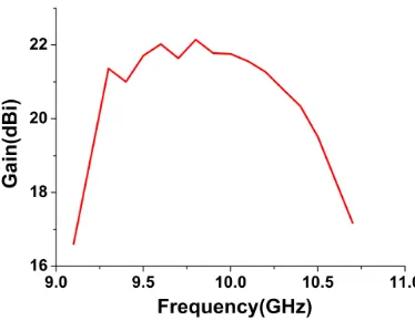
Abstract—In this letter, a four-layer transmitarray operating at 9.5 GHz is designed using a double-petal loop element as the unit cell. A configuration of the double-double-petal loop elements is used to increase transmission phase variation while maintaining a wide transmission magnitude bandwidth of the unit cell, and a full transmission phase range of 360◦ is achieved for a transmission magnitude equals to or better than−2.4 dB. Furthermore, the oblique performance of the unit cell is also good. Then, a prime-focus 676-element microstrip transmitarray with the proposed element is fabricated and measured. The highest measured gain is about 22.15 dBi at 9.8 GHz, resulting in a 31% aperture efficiency. The antenna bandwidth of 10.2% (from 9.3 to 10.3 GHz) for 1-dB gain is achieved in this design.
1. INTRODUCTION
The microstrip transmitarray is rapidly used in both terrestrial and satellite communication systems because of its advantages such as high gain, low mass and volume, inexpensive manufacture, and no insertion loss of a phased array’s feed network at millimeter wave frequencies [1–4]. Due to the planar array of printed patch elements, the transmitarray avoids the fabrication complexity inherent in lens antenna. Furthermore, the feed can be placed directly in front of the aperture without incurring the blockage losses of a reflectarray configuration, which usually results in high aperture efficiency [5, 6].
The two most important design criteria for a transmitarray element are its phase range and transmission magnitude. Firstly, in order for an element design to be suitable for a large array where there is possibly phase shifting range in the aperture fields, a phase tuning range of 360◦ is required. Secondly, the transmission magnitude needs to be close to 1 (0 dB) to ensure a high aperture efficiency. Thus, the design process must involve both the transmission phase shift and magnitude of the element. In addition, the severe drawback of the microstrip transmitarray is its limited bandwidth performance, which is usually 7% or less, and intense efforts have been made in recent years to overcome this shortcoming [1, 4, 5, 7] and [8]. In this paper, we present a novel transmitarray operating at 9.5 GHz which uses a double-petal loop as the unit cell element and offers a wider bandwidth than previously achieved ones.
To date, in order to obtain a transmission phase range of 360◦, while maintaining the high value of the transmission magnitude, there are many different techniques to control the transmission coefficient of each unit cell in the array. One approach involves using multilayer frequency selective surfaces [1, 5, 6] and [9]. This approach is popularly used to control the transmission magnitude and phase of each element in the array individually by varying the element dimensions. In [1], a four-layer double square ring transmitarray element, operating at 30 GHz, is designed to achieve the required transmission phase range of 360◦. A triple-layer transmitarray antenna is designed in [6], which achieves high gain of 28.9 dB at 11.3 GHz and bandwidths of 9% for 1-dB gain. Another approach is receiver-transmitter designs [10–13]. In this approach, a transmitarray antenna typically consists of two planar arrays of
Received 28 January 2016, Accepted 29 February 2016, Scheduled 17 March 2016
* Corresponding author: Chao Tian ([email protected]).
2. DOUBLE-PETAL LOOP TRANSMITARRAY ANTENNA DESIGN
A double-petal loop element shown in Figure 1 is simulated using Ansoft HFSS ver. 15. The phasing elements operate around resonance with unit cell periodicity of P = 15 mm ≈ 0.5λ. Here, λ stands for the free-space wavelength at the center frequency of 9.5 GHz. Periodic boundary conditions are introduced to take into account interactions with identical neighbor elements. The double-petal loop element is printed on a substrate with a relative permittivity of εr = 2.65. The substrate is suspended above ground plane with a distance of h1 = 8 mm, which is equal toλ/4. This configuration illustrates
that a unit cell of four identical conductor layers, separated by quarter wavelength air gaps, can achieve a full transmission phase range of 360◦ where the transmission magnitude is better than−2.4 dB. The relation of L1 and L2 is assumed as L2 = L1×K (0 < K <1). To validate the proposed design and
evaluate its magnitude and phase as well as bandwidth performances, a parametric study is carried out for variations of W and K.
(a) (b)
Figure 1. Geometry of the proposed element. (a) Top view and (b) side view.
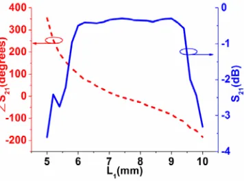
Figure 2 shows the transmission magnitude and phase versus the lengthL1at the center frequency of
9.5 GHz, which confirms the characteristic of 360◦transmission phase range with transmission magnitude better than −2.4 dB. Furthermore, a 300◦ phase range is achieved with magnitude better than −1 dB.
Figure 3 shows the influences ofW on the transmission coefficient of the proposed unit cell at the center frequency of 9.5 GHz. It can be concluded that width W can have a great influence on both transmission magnitude and phase. When W is equal to 0.2 mm and 0.5 mm, the phase ranges are respectively 350◦ and 360◦ with magnitude better than−3 dB for the proposed structure. Furthermore, whenW is equal to 0.3 mm, there are better linear transmission phase and magnitude for the proposed structure withL1 varying from 5 to 10 mm. It can also make the design less sensitive to manufacturing
error.
Figure 2. Transmission magnitude and phase versus the element dimensionL1 at the center frequency
of 9.5 GHz (W = 0.3 mm,K= 0.66).
(a) (b)
Figure 3. Transmission coefficients for differentW at the center frequency of 9.5 GHz (K = 0.66). (a) Magnitude and (b) phase.
(a) (b)
Figure 4. Transmission coefficients for different K at the center frequency of 9.5 GHz (W = 0.3 mm). (a) Magnitude and (b) phase.
transmission magnitude and phase. When K is equal to 0.5 and 0.75, the operating ranges of the transmission magnitude and phase do not agree with each other.
(a) (b)
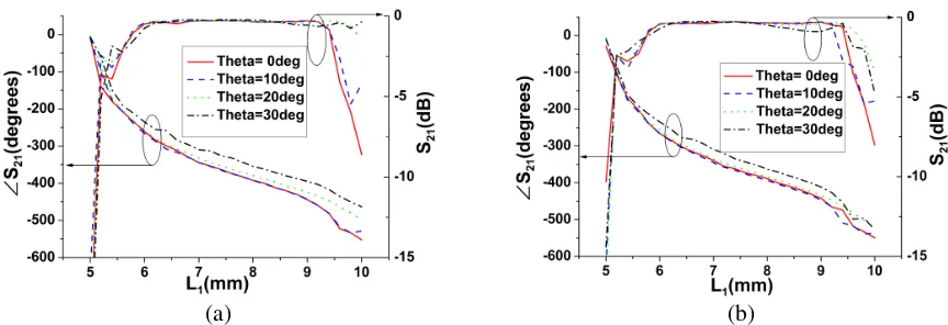
Figure 5. Transmission magnitude and phase of the unit cell versus L1 for different incident angle at
the center frequency of 9.5 GHz (W = 0.3,K = 0.66). (a) TM mode, (b) TE mode.
(a) (b)
Figure 6. Transmission coefficient versus the element dimensionL1 for different frequencies (W = 0.3,
K = 0.66). (a) Magnitude and (b) phase.
mode, with the increase of incidence angleθ, it can be noticed that the variations of both transmission magnitude and phase are acceptable. For TE mode, with the increase of incidence angle θ, there are small variations of the transmission magnitude and phase, except a bit descends at the element dimensions (8 mm< L1 <9 mm) with oblique incidence angle as high as θ= 30◦.
Magnitude and phase response versus length L1 for different frequencies (9.0–10.2 GHz) are also
researched, and the results are shown in Figure 6. It can be concluded that the proposed transmitarray element has a wide bandwidth.
According to the analysis of the proposed transmitarray element, it can be concluded that the element, consisting of double petal loops, can improve the bandwidth characteristics for a moderate size microstrip transmitarrays very well.
3. EXPERIMENTAL VALIDATION
In order to validate the effectiveness of the double-petal loop element, a prime-focus 676-element transmitarray is fabricated and measured. The transmitarray is fabricated on a 2 mm-thick dielectric substrate with εr = 2.65 and tanδ = 0.02. The separation between substrate layers is H = 8 mm. Photographs are shown in Figure 7. Both aperture sizeDand focal distanceF of the array are 195 mm, thus the ratio of F/Dis equal to 1.
(a)
(b)
Figure 7. Photographs of the designed 676-element transmitarray: (a) top view and (b) side view.
(a) (b)
Figure 8. The measured radiation patterns of the designed 676-element transmitarray. (a) E-plane, (b)H-plane.
Figure 9. Measured gain of the designed 676-element transmitarray.
REFERENCES
1. Ryan, C. G. M., M. Reza, J. Shaker, J. R. Bray, Y. M. M. Antar, and A. Ittipiboon, “A wideband transmitarray using dual-resonant double square rings,”IEEE Transactions on Antennas Propagation, Vol. 58, No. 5, 1486–1493, May 2010.
2. Bialkowski, M. E. and H. J. Song, “A Ku-band active transmit-array module with a horn or patch array as asignal launching/receiving device,”IEEE Transactions on Antennas Propagation, Vol. 49, No. 4, 535–541, Oct. 2001.
3. Ellinger, F., H. Jackel, and W. Bachtold, “Varactor-loaded transmission-line phase shifter at C-band using lumped elements,” IEEE Trans. Microw. Theory Tech., Vol. 51, No. 4, 1135–1140, 2003.
4. Kaouach, H., L. Dussopt, J. Lant´eri, R. Sauleau, and Th. Koleck, “Wideband low-loss linear and circular polarization transmit-array in V-band,” IEEE Transactions on Antennas Propagation, Vol. 59, No. 7, 2513–2523, Jul. 2011.
5. Abdelrahman, A. H., A. Z. Elsherbeni, and F. Yang, “Transmitarray antenna design using cross slot elements with no dielectric substrate,” IEEE Antennas and Wireless Propagation Letters, Vol. 13, 177–180, Feb. 2014.
6. Abdelrahman, A. H., A. Z. Elsherbeni, and F. Yang, “High gain and broadband transmitarray antenna using triple-layer spiral dipole elements,” IEEE Antennas and Wireless Propagation Letters, Vol. 13, 1288–1291, 2014.
7. Lau, J. Y. and S. V. Hum, “A wideband reconfigurable transmitarray element,” IEEE Transactions on Antennas Propagation, Vol. 60, 1303–1311, Mar. 2012.
8. Mahmoud, A. and A. Kishk, “Aperture coupled strip-line patch transmitarray,” IEEE Antennas Propag. Soc. Int. Symp. (USNC-URSI), 2015.
9. Mahmoud, A. E., W. Hong, Y. Zhang, and A. Kishk, “W-band multilayer perforated dielectric substrate lens,” IEEE Antennas and Wireless Propagation Letters, Vol. 13, 734–737, 2014.
10. Pozar, D. M., “Flat lens antenna concept using aperture coupled microstrip patches,” Electronics Letters, Vol. 32, 2109–2111, Nov. 1996.
11. Clemente, A., L. Dussopt, R. Sauleau, P. Potier, and P. Pouliguen, “Wideband 400-element electronically reconfigurable transmitarray in X band,” IEEE Transactions on Antennas Propagation, Vol. 61, No. 10, 5017–5027, Oct. 2013.
12. Padilla, P., A. M.-Acevedo, M. S.-Casta˜ner, and M. S.-P´erez, “Electronically reconfigurable transmitarray at Ku band for microwave applications,” IEEE Transactions on Antennas Propagation, Vol. 58, No. 8, 2571–2579, Aug. 2010.
13. De la Torre, P. P. and M. Sierra-Castaner, “Design and prototype of a 12-GHz transmit-array,” Microw. Opt. Technol. Lett., Vol. 49, No. 12, 3020–3026, Dec. 2007.
14. Kamada, S., N. Michishita, and Y. Yamada, “Metamaterial lens antenna using dielectric resonators for wide angle beam scanning,” Proc. IEEE Antennas Propag. Soc. Int. Symp. (APS-URSI), 1–4, 2010.